B101 NISSAN TIIDA 2010 Service Repair Manual
[x] Cancel search | Manufacturer: NISSAN, Model Year: 2010, Model line: TIIDA, Model: NISSAN TIIDA 2010Pages: 3745, PDF Size: 73.67 MB
Page 1562 of 3745
![NISSAN TIIDA 2010 Service Repair Manual P0447 EVAP CANISTER VENT CONTROL VALVEEC-297
< COMPONENT DIAGNOSIS > [HR16DE]
C
D
E
F
G H
I
J
K L
M A
EC
NP
O
YES >> GO TO 2.
NO >> GO TO 3.
2.CHECK EVAP CANISTER VENT CONTROL VALVE CIRCUIT
With CONSU](/img/5/57397/w960_57397-1561.png "NISSAN TIIDA 2010 Service Repair Manual P0447 EVAP CANISTER VENT CONTROL VALVEEC-297
< COMPONENT DIAGNOSIS > [HR16DE]
C
D
E
F
G H
I
J
K L
M A
EC
NP
O
YES >> GO TO 2.
NO >> GO TO 3.
2.CHECK EVAP CANISTER VENT CONTROL VALVE CIRCUIT
With CONSU")
P0447 EVAP CANISTER VENT CONTROL VALVEEC-297
< COMPONENT DIAGNOSIS > [HR16DE]
C
D
E
F
G H
I
J
K L
M A
EC
NP
O
YES >> GO TO 2.
NO >> GO TO 3.
2.CHECK EVAP CANISTER VENT CONTROL VALVE CIRCUIT
With CONSULT-III
1. Turn ignition switch OFF and then turn ON.
2. Select “VENT CONTROL/V” in “A CTIVE TEST” mode with CONSULT-III.
3. Touch “ON/OFF” on CONSULT-III screen.
4. Check for operating sound of the valve.
Is the inspection result normal?
YES >> GO TO 7.
NO >> GO TO 3.
3.CHECK EVAP CANISTER VENT CONT ROL VALVE POWER SUPPLY CIRCUIT
1. Turn ignition switch OFF.
2. Disconnect EVAP canister vent control valve harness connector.
3. Turn ignition switch ON.
4. Check the voltage between EVAP canister vent control valve harness connector and ground.
Is the inspection result normal?
YES >> GO TO 5.
NO >> GO TO 4.
4.DETECT MALFUNCTIONING PART
Check the following.
• Harness connectors E8, F8
• Harness connectors E7, M69
• Harness connectors M12, B101
• Harness for open or short between EVAP cani ster vent control valve and IPDM E/R
>> Repair open circuit or short to ground or short to power in harness or connectors.
5.CHECK EVAP CANISTER VENT CONTROL VALVE OUTPUT SIGNAL CIRCUIT FOR OPEN AND SHORT
1. Turn ignition switch OFF.
2. Disconnect ECM harness connector.
3. Check the continuity between EVAP canister vent control valve harness connector and ECM harness con- nector.
4. Also check harness for short to ground and short to power.
Is the inspection result normal?
YES >> GO TO 7.
NO >> GO TO 6.
6.DETECT MALFUNCTIONING PART
Check the following.
• Junction block connector F8, E8 Clicking sound should be heard.
EVAP canister vent control valve
Ground Voltage
Connector Terminal
B105 1 Ground Battery voltage
PBIB0080E
EVAP canister vent control valve ECM
Continuity
Connector Terminal Connector Terminal
B105 2E16 28 Existed
Revision: January 20102010 Versa
Page 1695 of 3745
![NISSAN TIIDA 2010 Service Repair Manual EC-430
< COMPONENT DIAGNOSIS >[HR16DE]
FUEL PUMP
NO >> Replace15 A fuse.
6.CHECK FUEL PUMP POWER SUPPLY CIRCUIT-IV
1. Disconnect IPDM E/R harness connector E45.
2. Check the continuity between IPDM E/](/img/5/57397/w960_57397-1694.png "NISSAN TIIDA 2010 Service Repair Manual EC-430
< COMPONENT DIAGNOSIS >[HR16DE]
FUEL PUMP
NO >> Replace15 A fuse.
6.CHECK FUEL PUMP POWER SUPPLY CIRCUIT-IV
1. Disconnect IPDM E/R harness connector E45.
2. Check the continuity between IPDM E/")
EC-430
< COMPONENT DIAGNOSIS >[HR16DE]
FUEL PUMP
NO >> Replace15 A fuse.
6.CHECK FUEL PUMP POWER SUPPLY CIRCUIT-IV
1. Disconnect IPDM E/R harness connector E45.
2. Check the continuity between IPDM E/R harness connector and “fuel level sensor unit and fuel pump”
harness connector.
3. Also check harness for short to ground and short to power.
Is the inspection result normal?
YES >> GO TO 10.
NO >> GO TO 7.
7.DETECT MALFUNCTIONING PART
Check the following.
• Harness connectors E7, M69
• Harness connectors M12, B101
• Harness for open or short between IPDM E/R and “fuel level sensor unit and fuel pump”
>> Repair open circuit or short to power in harness or connectors.
8.CHECK FUEL PUMP GROUND CIRCUIT
1. Check the continuity between “fuel le vel sensor unit and fuel pump” and ground.
2. Also heck harness for short to power.
Is the inspection result normal?
YES >> GO TO 9.
NO >> Repair open circuit or short to power in harness or connectors.
9.CHECK FUEL PUMP
Refer to EC-430, "
Component Inspection".
Is the inspection result normal?
YES >> GO TO 10.
NO >> Replace “fuel level sensor unit and fuel pump”.
10.CHECK INTERMITTENT INCIDENT
Refer to EC-114, "
Diagnosis Procedure".
Is the inspection result normal?
YES >> Replace IPDM E/R.
NO >> Repair or replace harness or connectors.
Component InspectionINFOID:0000000005398613
1.CHECK FUEL PUMP
1. Turn ignition switch OFF.
2. Disconnect “fuel level sensor uni t and fuel pump” harness connector.
IPDM E/RFuel level sensor unit and
fuel pump Continuity
Connector Terminal Connector Terminal
E45 36 B100 1 Existed
Fuel level sensor unit and fuel pump Ground Continuity
Connector Terminal
B100 3 Ground Existed
Revision: January 20102010 Versa
Page 2104 of 3745
![NISSAN TIIDA 2010 Service Repair Manual DTC P0447 EVAP CANISTER VENT CONTROL VALVE
EC-839
< SERVICE INFORMATION > [MR18DE]
C
D
E
F
G H
I
J
K L
M A
EC
NP
O
4. Check voltage between EVAP canister vent control valve termi-
nal 1 and ground wit](/img/5/57397/w960_57397-2103.png "NISSAN TIIDA 2010 Service Repair Manual DTC P0447 EVAP CANISTER VENT CONTROL VALVE
EC-839
< SERVICE INFORMATION > [MR18DE]
C
D
E
F
G H
I
J
K L
M A
EC
NP
O
4. Check voltage between EVAP canister vent control valve termi-
nal 1 and ground wit")
DTC P0447 EVAP CANISTER VENT CONTROL VALVE
EC-839
< SERVICE INFORMATION > [MR18DE]
C
D
E
F
G H
I
J
K L
M A
EC
NP
O
4. Check voltage between EVAP canister vent control valve termi-
nal 1 and ground with CONSULT-III or tester.
OK or NG
OK >> GO TO 5.
NG >> GO TO 4.
4.DETECT MALFUNCTIONING PART
Check the following.
• Harness connectors E8, F8
• Harness connectors E7, M69
• Harness connectors M12, B101
• Harness for open or short between EVAP cani ster vent control valve and IPDM E/R
>> Repair open circuit or short to ground or short to power in harness or connectors.
5.CHECK EVAP CANISTER VENT CONTROL VALVE OUTPUT SIGNAL CIRCUIT FOR OPEN AND SHORT
1. Turn ignition switch OFF.
2. Disconnect ECM harness connector.
3. Check harness continuity between ECM terminal 28 and EVAP canister vent control valve terminal 2.
Refer to Wiring Diagram.
4. Also check harness for short to ground and short to power.
OK or NG
OK >> GO TO 7.
NG >> GO TO 6.
6.DETECT MALFUNCTIONING PART
Check the following.
• Harness connectors E8, F8
• Harness connectors E7, M69
• Harness connectors M13, B102
• Harness for open or short between EVAP c anister vent control valve and ECM
>> Repair open circuit or short to ground or short to power in harness or connectors.
7.CHECK RUBBER TUBE FOR CLOGGING
1. Disconnect rubber tube connected to EV AP canister vent control valve.
2. Check the rubber tube for clogging.
OK or NG
OK >> GO TO 8.
NG >> Clean the rubber tube using an air blower.
8.CHECK DRAIN FILTER
Refer to EC-814, "
Component Inspection".
OK or NG
OK >> GO TO 9.
NG >> Replace drain filter.
9.CHECK EVAP CANISTER VENT CONTROL VALVE
Refer to EC-840, "
Component Inspection".
Voltage: Battery voltage
PBIB0080E
Continuity should exist.
Revision: January 20102010 Versa
Page 2282 of 3745
![NISSAN TIIDA 2010 Service Repair Manual FUEL PUMPEC-1017
< SERVICE INFORMATION > [MR18DE]
C
D
E
F
G H
I
J
K L
M A
EC
NP
O
4.DETECT MALFUNCTIONING PART
Check the following.
• Harness connectors E8, F8
• Harness for open or short between](/img/5/57397/w960_57397-2281.png "NISSAN TIIDA 2010 Service Repair Manual FUEL PUMPEC-1017
< SERVICE INFORMATION > [MR18DE]
C
D
E
F
G H
I
J
K L
M A
EC
NP
O
4.DETECT MALFUNCTIONING PART
Check the following.
• Harness connectors E8, F8
• Harness for open or short between")
FUEL PUMPEC-1017
< SERVICE INFORMATION > [MR18DE]
C
D
E
F
G H
I
J
K L
M A
EC
NP
O
4.DETECT MALFUNCTIONING PART
Check the following.
• Harness connectors E8, F8
• Harness for open or short between IPDM E/R and ECM
>> Repair open circuit or short to ground or short to power in harness or connectors.
5.CHECK FUEL PUMP POWER SUPPLY CIRCUIT-III
1. Turn ignition switch OFF.
2. Reconnect all harness connectors disconnected.
3. Disconnect “fuel level sensor unit and fuel pump” harness con- nector (1).
- Illustration shows the view with inspection hole cover removed.
4. Turn ignition switch ON.
5. Check voltage between “fuel level sensor unit and fuel pump”
terminal 1 and ground with CONSULT-III or tester.
OK or NG
OK >> GO TO 9.
NG >> GO TO 6.
6.CHECK 15 A FUSE
1. Turn ignition switch OFF.
2. Disconnect 15 A fuse.
3. Check 15 A fuse.
OK or NG
OK >> GO TO 7.
NG >> Replace fuse.
7.CHECK FUEL PUMP POWER SUPPLY CIRCUIT-IV
1. Disconnect IPDM E/R harness connector E45.
2. Check harness continuity between IPDM E/R terminal 36 and “fuel level sensor unit and fuel pump” termi-
nal 1. Refer to Wiring Diagram.
3. Also check harness for short to ground and short to power.
OK or NG
OK >> GO TO 11.
NG >> GO TO 8.
8.DETECT MALFUNCTIONING PART
Check the following.
• Harness connectors M69, E7
• Harness connectors M12, B101
BBIA0702E
Voltage: Battery voltage should exist for 1 second after ignition switch is turned ON.
PBIB0795E
Continuity should exist.
Revision: January 20102010 Versa
Page 3424 of 3745

HARNESSPG-41
< SERVICE INFORMATION >
C
DE
F
G H
I
J
L
M A
B
PG
N
O P
C2 M6 W/4 : Steering lock solenoid D2 M43 W/20 : Audio unit
B3 M7 W/16 : Door mirror re mote control switch D2 M44 W/16 : Audio unit
A3 M8 W/16 : To D2 D2 M45 W/12 : Audio unit
A3 M9 W/16 : To D1 A1 M46 BR/2 : Front tweeter LH
E2 M10 GR/2 : Instrument panel antenna G1 M47 BR/2 : Front tweeter RH
G3 M11 W/4 : To B106 B2 M48 L/4 : Heated mirror relay
G4 M12 W/16 : To B101 E1 M49 W/24 : iPod ® adapter
G3 M13 W/24 : To B102 E1 M50 GR/16 : iPod ® side
G3 M14 W/24 : To B120 E2 M52 W/40 : Intelligent key unit
B4 M15 W/16 : To B23 B2 M53 W/16 : EPS control unit
B4 M16 W/24 : To B24 B3 M54 B/2 : EPS control unit
D5 M17 B/1 : Parking brake switch D2 M55 W/4 : Hazard switch
F2 M18 W/40 : BCM (body control module) B2 M57 — : Body ground
F2 M19 W/15 : BCM (body control module) F2 M59 W/2 : Glove box lamp
F3 M20 B/15 : BCM (body control module)C1 M60 L/2 : EPS control unit
C2 M21 W/4 : NATS antenna amp. F1 M61 — : Body ground
B3 M22 W/16 : Data link connector E2 M62 W/2 : Front blower motor
E3 M23 W/4 : Remote keyless entry receiver C1 M63 W/4 : Torque sensor
C1 M24 W/40 : Combination meter C3 M64 W/8 : Steering angle sensor
C3 M25 /2 : Diode-1 A2 M69 SMJ : To E7
B2 M26 W/6 : Ignition switch D2 M70 W/24 : AV control unit
C2 M27 GR/6 : Key switch and key lock solenoid D2 M71 W/9 : AV control unit
C2 M28 W/16 : Combination switch D1 M72 B/5 : USB interface and aux jack
C3 M29 Y/6 : Combination switch B2 M73 GR/6 : Key switch and ignition knob switch
C3 M30 GR/8 : Combination switch G3 M74 W/12 : To D102
A4 M31 W/24 : To B1 G3 M75 W/12 : To D101
E3 M32 W/4 : To M150 E1 M76 B/4 : USB interface and aux jack
D2 M33 B/15 : Front air control F2 M77 Y/4 : Front passenger air bag module
B3 M34 GR/6 : VDC OFF switch A2 M78 B/2 : To E11
D4 M35 Y/28 : Air bag diagnosis sensor unit B1 M79 — : Body ground
C3 M36 W/3 : Front passenger air bag OFF indicator D3 M150 W/4 : To M32
D4 M38 W/6 : A/T shift selector (with A/T) C3 M151 W/4 : Front blower motor resistor
D4 M38 W/6 : CVT shift selector (without intelligent
key)
Revision: January 20102010 Versa
Page 3433 of 3745
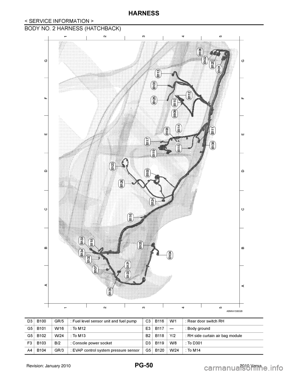
PG-50
< SERVICE INFORMATION >
HARNESS
BODY NO. 2 HARNESS (HATCHBACK)
ABMIA1595GB
D3 B100 GR/5 : Fuel level sensor unit and fuel pump C3 B116 W/1 : Rear door switch RH
G5 B101 W/16 : To M12E3 B117 — : Body ground
G5 B102 W/24 : To M13 B2 B118 Y/2 : RH side curtain air bag module
F3 B103 B/2 : Console power socket D3 B119 W/8 : To D301
A4 B104 GR/3 : EVAP control system pressure sensor G5 B120 W/24 : To M14
Revision: January 20102010 Versa
Page 3435 of 3745
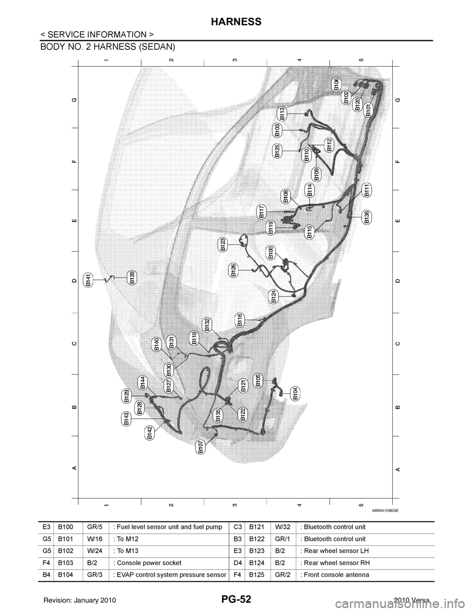
PG-52
< SERVICE INFORMATION >
HARNESS
BODY NO. 2 HARNESS (SEDAN)
ABMIA1596GB
E3 B100 GR/5 : Fuel level sensor unit and fuel pump C3 B121 W/32 : Bluetooth control unit
G5 B101 W/16 : To M12B3 B122 GR/1 : Bluetooth control unit
G5 B102 W/24 : To M13 E3 B123 B/2 : Rear wheel sensor LH
F4 B103 B/2 : Console power socket D4 B124 B/2 : Rear wheel sensor RH
B4 B104 GR/3 : EVAP control system pressure sensor F4 B125 GR/2 : Front console antenna
Revision: January 20102010 Versa
Page 3616 of 3745
![NISSAN TIIDA 2010 Service Repair Manual TROUBLE DIAGNOSISSRS-23
< SYMPTOM DIAGNOSIS >
C
DE
F
G
I
J
K L
M A
B
SRS
N
O P
CURTAIN MODULE LH [OPEN][B1150] The LH side curtain air bag module circuit is open.
1. Visually check the wiring harness](/img/5/57397/w960_57397-3615.png "NISSAN TIIDA 2010 Service Repair Manual TROUBLE DIAGNOSISSRS-23
< SYMPTOM DIAGNOSIS >
C
DE
F
G
I
J
K L
M A
B
SRS
N
O P
CURTAIN MODULE LH [OPEN][B1150] The LH side curtain air bag module circuit is open.
1. Visually check the wiring harness")
TROUBLE DIAGNOSISSRS-23
< SYMPTOM DIAGNOSIS >
C
DE
F
G
I
J
K L
M A
B
SRS
N
O P
CURTAIN MODULE LH [OPEN][B1150] The LH side curtain air bag module circuit is open.
1. Visually check the wiring harness
connection.
2. Replace the harness if it has visi- ble damage.
3. Replace LH side curtain air bag module.
4. Replace the air bag diagnosis
sensor unit.
5. Replace the related harness.
CURTAIN MODULE LH
[VB-SHORT]
[B1151] The LH side curtain air bag module circuit is shorted to some
power supply circuits.
CURTAIN MODULE LH [GND-SHORT][B1152] The LH side curtain air bag module circuit is shorted to
ground.
CURTAIN MODULE LH [SHORT][B1153] The circuits for the LH side curtain air bag module are shorted
to each other.
CURTAIN MODULE RH [OPEN]
[B1145] The RH side curtain air bag module circuit is open.
1. Visually check the wiring harness
connection.
2. Replace the harness if it has visi- ble damage.
3. Replace RH side curtain air bag
module.
4. Replace the air bag diagnosis sensor unit.
5. Replace the related harness.
CURTAIN MODULE RH
[VB-SHORT][B1146] The RH side curtain air bag module circuit is shorted to some
power supply circuits.
CURTAIN MODULE RH [GND-SHORT][B1147] The RH side curtain air bag module circuit is shorted to
ground.
CURTAIN MODULE RH [SHORT]
[B1148] The circuits for the RH side curtain air bag module are shorted
to each other.
CONTROL UNIT [B1XXX] Air bag diagnosis sensor unit is malfunctioning.
1. Visually check the wiring harness
connection.
2. Replace the air bag diagnosis
sensor unit.
OCCUPANT SENS C/U [UNIT FAIL]
[B1017] or [B1021] The OCS control unit is malfunctioning.
1. Replace RH front seat cushion/
occupant classification system
control unit assembly.
OCCUPANT SENS C/U [UNIT FAIL]
[B1020] The OCS control unit is malfunctioning.
1. Replace the harness if it has visi-
ble damage.
2. Replace the RH front seat cush- ion assembly. Do not disassem-
ble the seat cushion assembly.
3. Replace the RH front seat belt as- sembly.
OCCUPANT SENS C/U [COMM FAIL][B1022] Communication between the OCS control unit and air bag di-
agnosis sensor unit is interrupted.
1. Visually check the wiring harness
connection.
2. Replace the harness if it has visi- ble damage.
3. Replace the RH front seat cush-
ion assembly. Do not disassem-
ble the seat cushion assembly.
4. Replace the air bag diagnosis
sensor unit.
5. Replace the related harness.
OCCUPANT SENS [UNIT FAIL][B1018] OCS sensor is malfunctioning.
1. Visually check the wiring harness
connection to the OCS sensor.
2. Replace the RH front seat cush- ion assembly. Do not disassem-
ble the seat cushion assembly.
Diagnostic item
Explanation Repair order
Recheck SRS at each replacement
Revision: January 20102010 Versa
Page 3617 of 3745

SRS-24
< SYMPTOM DIAGNOSIS >
TROUBLE DIAGNOSIS
NOTE:
Follow the procedures in numerical order when performing repairs. Confirm whether the repair has been suc-
cessful using air bag warning lamp or CONSULT-III after each repair. If malfunction is still observed, proceed
to the next step. When malfunction has been elimi nated, further repair work is not required.
DIAGNOSTIC PROCEDURE 3
Final Check of SRS Using CONSULT-III—Diagnosis Mode
1. If no DTC is detected on “SELF-DIAG [CURRENT]”, repair of SRS is completed. Go to step 2.
If any DTC is detected on “SELF-DIAG [CURRENT]” , the malfunctioning part has not been repaired com-
pletely or another malfunctioning part is being detected. Go to "DIAGNOSTIC PROCEDURE 2".
2. Touch “ERASE”. NOTE:
Touch “ERASE” to clear the memory of the malfunction (“SELF-DIAG [PAST]”).
If the memory of the malfunction in “SELF-DIAG [P AST]” is not erased, the User mode shows the system
malfunction by the operation of the warning lamp even if the malfunction is repaired completely.
3. Touch “BACK” key of CONSULT-III to “SELECT DIAG MODE” screen. Touch “SELF-DIAG [PAST]”.
4. Check that no malfunction is detected on “SELF-DIAG [PAST]”.
5. Touch “BACK” key of CONSULT-III until “SELECT SY STEM” appears in order to return to User mode from
Diagnosis mode.
6. Turn ignition switch OFF then turn off and disconnect CONSULT-III.
7. Go to SRS-19, "
SRS Operation Check".
DIAGNOSTIC PROCEDURE 4
Check SRS Repair History
1.CONSIDER POSSIBILITY THAT SELF-DIAGNOSTIC RESULT WAS NOT ERASED AFTER REPAIR
Check repair history of the SRS.
Have any previous repairs been made to the SRS?
Yes >> Self-diagnostic result “SELF-DIAG [PAST]” (pre viously stored in the memory) might not be erased
after repair. Go to "DIAGNOSTIC PROCEDURE 3".
No >> Go to "DIAGNOSTIC PROCEDURE 2".
DIAGNOSTIC PROCEDURE 5
Check SRS Intermittent Malfuncti on Using CONSULT-III—Diagnosis Mode
1. If diagnostic codes are displayed on “SELF-DIAG [PAST]”, go to step 4.
If no malfunction is detected on “SELF-DIAG [PAS T]”, touch “BACK” and go back to “SELECT DIAG
MODE”.
BELT TENSION SENS
[UNIT FAIL]
[B1019] Belt tension sensor is malfunctioning.
1. Visually check the wiring harness
connection.
2. Replace the harness if it has visi- ble damage.
3. Replace the RH front seat belt as- sembly.
4. Replace the RH front seat cush-
ion assembly. Do not disassem-
ble the seat cushion assembly.
5. Replace the related harness.
FRONTAL COLLISION DETECTION[B1209] Driver and front passenger air bag modules are deployed. Refer to
SRS-48
.
SIDE COLLISION DETECTION
[B1210] Side or curtain air bag modules are deployed.
Diagnostic item
Explanation Repair order
Recheck SRS at each replacement
Revision: January 20102010 Versa
Page 3620 of 3745
![NISSAN TIIDA 2010 Service Repair Manual TROUBLE DIAGNOSISSRS-27
< SYMPTOM DIAGNOSIS >
C
DE
F
G
I
J
K L
M A
B
SRS
N
O P
PRE-TEN FRONT LH [OPEN]
[B1086] The circuit for front LH seat belt pre-tensioner is open. 1. Visually check the wiring h](/img/5/57397/w960_57397-3619.png "NISSAN TIIDA 2010 Service Repair Manual TROUBLE DIAGNOSISSRS-27
< SYMPTOM DIAGNOSIS >
C
DE
F
G
I
J
K L
M A
B
SRS
N
O P
PRE-TEN FRONT LH [OPEN]
[B1086] The circuit for front LH seat belt pre-tensioner is open. 1. Visually check the wiring h")
TROUBLE DIAGNOSISSRS-27
< SYMPTOM DIAGNOSIS >
C
DE
F
G
I
J
K L
M A
B
SRS
N
O P
PRE-TEN FRONT LH [OPEN]
[B1086] The circuit for front LH seat belt pre-tensioner is open. 1. Visually check the wiring harness
connections.
2. Replace the harness if it has visi- ble damage.
3. Replace front LH seat belt pre- tensioner.
4. Replace the air bag diagnosis
sensor unit.
5. Replace the related harness.
PRE-TEN FRONT LH
[VB-SHORT]
[B1087] The circuit for front LH seat belt pre-tensioner is shorted to
some power supply circuit.
PRE-TEN FRONT LH [GND-SHORT] [B1088] The circuit for front LH seat belt pre-tensioner is shorted to
ground.
PRE-TEN FRONT LH [SHORT][B1089] The circuits for the front LH seat belt pre-tensioner are shorted
to each other.
PRE-TEN FRONT RH [OPEN]
[B1081] The circuit for front RH seat belt pre-tensioner is open. 1. Visually check the wiring harness
connections.
2. Replace the harness if it has visi- ble damage.
3. Replace front RH seat belt pre-
tensioner.
4. Replace the air bag diagnosis sensor unit.
5. Replace the related harness.
PRE-TEN FRONT RH
[VB-SHORT][B1082] The circuit for front RH seat belt pre-tensioner is shorted to
some power supply circuit.
PRE-TEN FRONT RH [GND-SHORT][B1083] The circuit for front RH seat belt pre-tensioner is shorted to
ground.
PRE-TEN FRONT RH [SHORT]
[B1084] The circuits for the front RH seat belt pre-tensioner are short-
ed to each other.
CURTAIN MODULE LH [OPEN][B1150] The LH side curtain air bag module circuit is open.
1. Visually check the wiring harness
connection.
2. Replace the harness if it has visi-
ble damage.
3. Replace LH side curtain air bag module.
4. Replace the air bag diagnosis sensor unit.
5. Replace the related harness.
CURTAIN MODULE LH
[VB-SHORT][B1151] The LH side curtain air bag module circuit is shorted to some
power supply circuits.
CURTAIN MODULE LH [GND-SHORT]
[B1152] The LH side curtain air bag module circuit is shorted to
ground.
CURTAIN MODULE LH [SHORT][B1153] The circuits for the LH side curtain air bag module are shorted
to each other.
CURTAIN MODULE RH [OPEN]
[B1145] The RH side curtain air bag module circuit is open.
1. Visually check the wiring harness
connection.
2. Replace the harness if it has visi- ble damage.
3. Replace RH side curtain air bag
module.
4. Replace the air bag diagnosis sensor unit.
5. Replace the related harness.
CURTAIN MODULE RH
[VB-SHORT][B1146] The RH side curtain air bag module circuit is shorted to some
power supply circuits.
CURTAIN MODULE RH [GND-SHORT][B1147] The RH side curtain air bag module circuit is shorted to
g
r
ound.
CURTAIN MODULE RH [SHORT]
[B1148] The circuits for the RH side curtain air bag module are shorted
to each other.
CONTROL UNIT [B1XXX] Air bag diagnosis sensor unit is malfunctioning.
1. Visually check the wiring harness
connection.
2. Replace the air bag diagnosis
sensor unit.
OCCUPANT SENS C/U [UNIT FAIL]
[B1017], [B1020] or [B1021] Occupant classification system is malfunctioning.
1. Replace RH front seat cushion/
occupant classification system
control unit assembly.
Diagnostic item
Explanation Repair order
Recheck SRS at each replacement
Revision: January 20102010 Versa