ECO NISSAN TIIDA 2010 Service Repair Manual
[x] Cancel search | Manufacturer: NISSAN, Model Year: 2010, Model line: TIIDA, Model: NISSAN TIIDA 2010Pages: 3745, PDF Size: 73.67 MB
Page 1 of 3745
-1
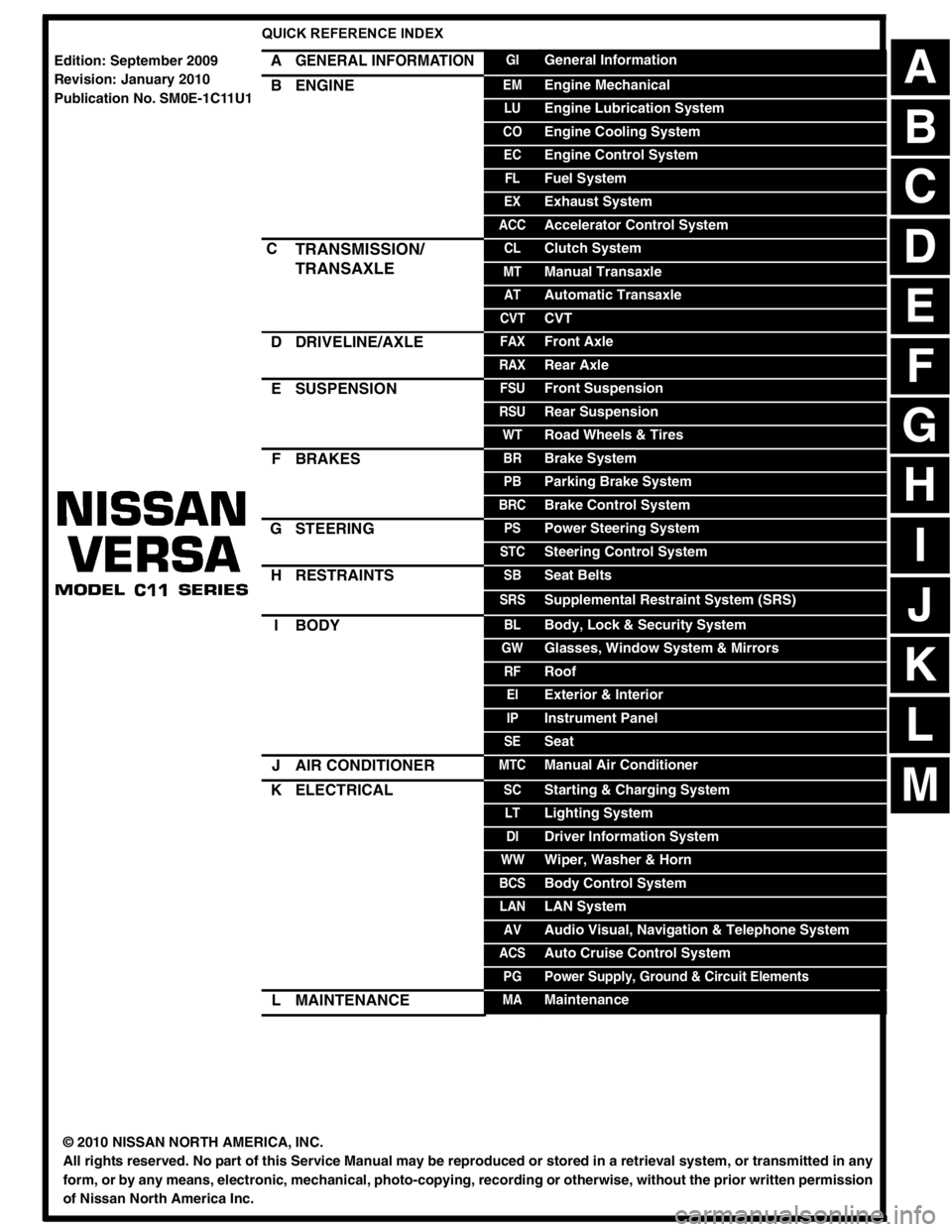
QUICK REFERENCE INDEX
AGENERAL INFORMATIONGIGeneral Information
BENGINEEMEngine Mechanical
LUEngine Lubrication System
COEngine Cooling System
ECEngine Control System
FLFuel System
EXExhaust System
ACCAccelerator Control System
CTRANSMISSION/
TRANSAXLECLClutch System
MTManual Transaxle
ATAutomatic Transaxle
CVTCVT
DDRIVELINE/AXLEFAXFront Axle
RAXRear Axle
ESUSPENSIONFSUFront Suspension
RSURear Suspension
WTRoad Wheels & Tires
FBRAKESBRBrake System
PBParking Brake System
BRCBrake Control System
GSTEERINGPSPower Steering System
STCSteering Control System
HRESTRAINTSSBSeat Belts
SRSSupplemental Restraint System (SRS)
IBODYBLBody, Lock & Security System
GWGlasses, Window System & Mirrors
RFRoof
EIExterior & Interior
IPInstrument Panel
SESeat
JAIR CONDITIONERMTCManual Air Conditioner
KELECTRICALSCStarting & Charging System
LTLighting System
DIDriver Information System
WWWiper, Washer & Horn
BCSBody Control System
LANLAN System
AVAudio Visual, Navigation & Telephone System
ACSAuto Cruise Control System
PGPower Supply, Ground & Circuit Elements
LMAINTENANCEMAMaintenance
Edition: September 2009
Revision: January 2010
Publication No. SM0E-1C11U1
B
D
© 2010 NISSAN NORTH AMERICA, INC.
All rights reserved. No part of this Service Manual may be reproduced or stored in a retrieval system, or transmitted in any
form, or by any means, electronic, mechanical, photo-copying, recording or otherwise, without the prior written permission
of Nissan North America Inc.
A
C
E
F
G
H
I
J
K
L
M
Page 2 of 3745
-2
This manual contains maintenance and repair procedures for the
2010 NISSAN VERSA.
In order to assure your safety and the efficient functioning of the vehicle,
this manual should be read thoroughly. It is especially important that the
PRECAUTIONS in the GI section be completely understood before starting
any repair task.
All information in this manual is based on the latest product information
at the time of publication. The right is reserved to make changes in specifi-
cations and methods at any time without notice.
IMPORTANT SAFETY NOTICE
The proper performance of service is essential for both the safety of
the technician and the efficient functioning of the vehicle.
The service methods in this Service Manual are described in such a
manner that the service may be performed safely and accurately.
Service varies with the procedures used, the skills of the technician
and the tools and parts available. Accordingly, anyone using service
procedures, tools or parts which are not specifically recommended
by NISSAN must first be completely satisfied that neither personal
safety nor the vehicle’s safety will be jeopardized by the service
method selected.
Page 3 of 3745

PLEASEHELPMAKETHISSERVICEMANUALBETTER!
YourcommentsareimportanttoNISSANandwillhelpustoimproveourServiceManuals.
UsethisformtoreportanyissuesorcommentsyoumayhaveregardingourServiceManuals.
Pleaseprintthisformandtypeorwriteyourcommentsbelow.Mailorfaxto:
NissanNorthAmerica,Inc.
TechnicalServiceInformation
39001SunriseDrive,P.O.Box9200
FarmingtonHills,MIUSA48331
FAX:(248)488-3910
SERVICEMANUAL:Model:Year:
PUBLICATIONNO.(Refer to Quick Reference Index ):
Pleasedescribeany Service Manualissuesorproblemsindetail:
Pagenumber(s)Note:Pleaseincludeacopyofeachpage,markedwithyourcomments.
Arethetroublediagnosisprocedureslogicalandeasytouse?(circleyouranswer)YESNO
Ifno,whatpagenumber(s)?Note:Pleaseincludeacopyofeachpage,markedwithyourcomments.
Pleasedescribetheissueorproblemindetail:
Istheorganizationofthemanualclearandeasytofollow?(circleyouranswer)YESNO
Pleasecomment:
WhatinformationshouldbeincludedinNISSANServiceManualstobettersupportyouinservicingor
repairingcustomervehicles?
DATE:YOURNAME:POSITION:
DEALER:DEALERNO.:ADDRESS:
CITY:STATE/PROV./COUNTRY:ZIP/POSTALCODE:
Page 6 of 3745
2010
QUICK REFERENCE CHART: VERSA
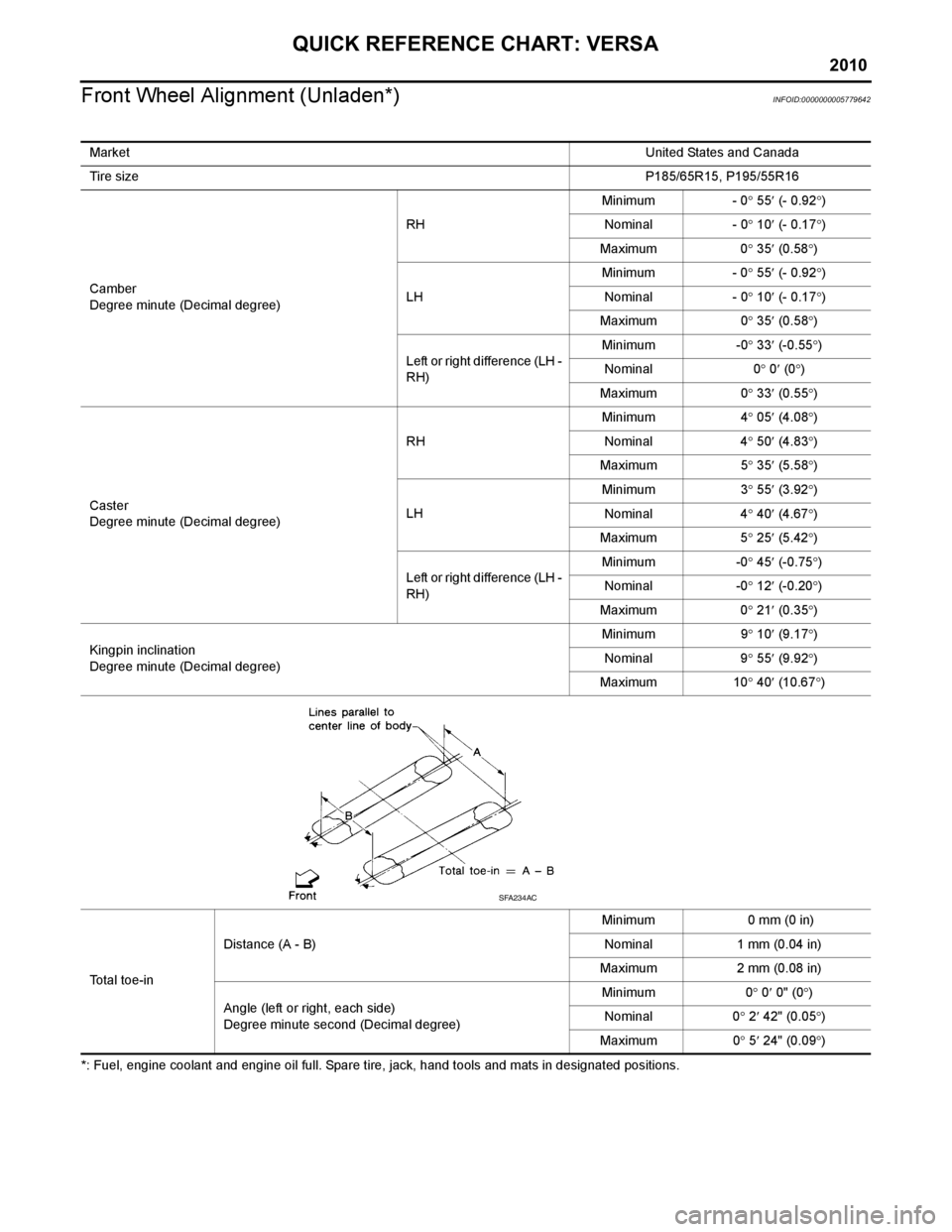
Front Wheel Alignment (Unladen*)
INFOID:0000000005779642
*: Fuel, engine coolant and engine oil full. Spare tire, jack, hand tools and mats in designated positions. Market
United States and Canada
Tire size P185/65R15, P195/55R16
Camber
Degree minute (Decimal degree) RH
Minimum - 0
° 55 ′ (- 0.92 °)
Nominal - 0 ° 10 ′ (- 0.17 °)
Maximum 0 ° 35 ′ (0.58 °)
LH Minimum - 0
° 55 ′ (- 0.92 °)
Nominal - 0 ° 10 ′ (- 0.17 °)
Maximum 0 ° 35 ′ (0.58 °)
Left or right difference (LH -
RH) Minimum -0
° 33 ′ (-0.55 °)
Nominal 0 ° 0 ′ (0 °)
Maximum 0 ° 33 ′ (0.55 °)
Caster
Degree minute (Decimal degree) RH
Minimum 4
° 05 ′ (4.08 °)
Nominal 4 ° 50 ′ (4.83 °)
Maximum 5 ° 35 ′ (5.58 °)
LH Minimum 3
°
55′ (3.92 °)
Nominal 4 ° 40 ′ (4.67 °)
Maximum 5 ° 25 ′ (5.42 °)
Left or right difference (LH -
RH) Minimum -0
° 45 ′ (-0.75 °)
Nominal -0 ° 12 ′ (-0.20 °)
Maximum 0 ° 21 ′ (0.35 °)
Kingpin inclination
Degree minute (Decimal degree) Minimum 9
° 10 ′ (9.17 °)
Nominal 9 ° 55 ′ (9.92 °)
Maximum 10 ° 40 ′ (10.67 °)
Total toe-in Distance (A - B)
Minimum 0 mm (0 in)
Nominal 1 mm (0.04 in)
Maximum 2 mm (0.08 in)
Angle (left or right, each side)
Degree minute second (Decimal degree) Minimum 0
° 0 ′ 0" (0 °)
Nominal 0 ° 2 ′ 42" (0.05 °)
Maximum 0 ° 5 ′ 24" (0.09 °)
SFA234AC
Page 9 of 3745

QUICK REFERENCE CHART: VERSA
2010
MR18DE
Front brake Brake model AD22VKCylinder bore diameter 53.97 mm (2.125 in)
Pad
Length × width × thickness 11 5 . 0 m m
× 41.0 mm × 9.0 mm
(4.528 in × 1.614 in × 0.354 in)
Rotor outer diameter × thickness 260 mm × 22.0 mm (10.24 in × 0.866 in)
Rear brake Brake model LT20 Cylinder bore diameter 15.87 mm (0.625 in) 17.46 mm (0.687 in)
Drum inner diameter 203 mm (7.992 in)
Master cylinder Cylinder bore diameter 22.22 mm (0.875 in)
Brake booster Booster model C255 Diaphragm diameter 255 mm (10.04 in)
Recommended brake fluid DOT 3
Front brake Brake model CLZ25VF Cylinder bore diameter 57.2 mm (2.252 in)
Pad
Length × width × thickness 125.6 mm
× 48.0 mm × 9.5 mm
(4.945 in × 1.890 in × 0.374 in)
Rotor outer diameter × thickness 280 mm × 24.0 mm (11.02 in × 0.945 in)
Rear brake Brake model LT23 Cylinder bore diameter 19.06 mm (0.750 in)
Drum inner diameter 228.6 mm (9.000 in)
Master cylinder Cylinder bore diameter 23.81 ± 0.015 mm (0.937 ± 0.001 in)
Brake booster Booster model C255 Diaphragm diameter 255 mm (10.04 in)
Recommended brake fluid DOT 3
Page 13 of 3745

ACC-2
< SERVICE INFORMATION >
PRECAUTIONS
SERVICE INFORMATION
PRECAUTIONS
Precaution for Supplemental Restraint System (SRS) "AIR BAG" and "SEAT BELT
PRE-TENSIONER"
INFOID:0000000005714391
The Supplemental Restraint System such as “A IR BAG” and “SEAT BELT PRE-TENSIONER”, used along
with a front seat belt, helps to reduce the risk or severity of injury to the driver and front passenger for certain
types of collision. This system includes seat belt switch inputs and dual stage front air bag modules. The SRS
system uses the seat belt switches to determine the front air bag deployment, and may only deploy one front
air bag, depending on the severity of a collision and w hether the front occupants are belted or unbelted.
Information necessary to service the system safely is included in the SRS and SB section of this Service Man-
ual.
WARNING:
• To avoid rendering the SRS inopera tive, which could increase the risk of personal injury or death in
the event of a collision which would result in air bag inflation, all maintenance must be performed by
an authorized NISSAN/INFINITI dealer.
• Improper maintenance, including incorrect removal and installation of the SRS can lead to personal
injury caused by unintent ional activation of the system. For re moval of Spiral Cable and Air Bag
Module, see the SRS section.
• Do not use electrical test equipmen t on any circuit related to the SRS unless instructed to in this
Service Manual. SRS wiring harn esses can be identified by yellow and/or orange harnesses or har-
ness connectors.
PRECAUTIONS WHEN USING POWER TOOLS (AIR OR ELECTRIC) AND HAMMERS
WARNING:
• When working near the Airbag Diagnosis Sensor Unit or other Airbag System sensors with the Igni-
tion ON or engine running, DO NOT use air or electri c power tools or strike near the sensor(s) with a
hammer. Heavy vibration could activate the sensor( s) and deploy the air bag(s), possibly causing
serious injury.
• When using air or electric power tools or hammers , always switch the Ignition OFF, disconnect the
battery, and wait at least 3 minu tes before performing any service.
Precaution Necessary for Steering W heel Rotation After Battery Disconnect
INFOID:0000000005399822
NOTE:
• This Procedure is applied only to models with Intelligent Key system and NATS (NISSAN ANTI-THEFT SYS-
TEM).
• Remove and install all control units after disconnecting both battery cables with the ignition knob in the
″LOCK ″ position.
• Always use CONSULT-III to perform self-diagnosis as a part of each function inspection after finishing work.
If DTC is detected, perform trouble diagnosis according to self-diagnostic results.
For models equipped with the Intelligent Key system and NATS, an electrically controlled steering lock mech-
anism is adopted on the key cylinder.
For this reason, if the battery is disconnected or if the battery is discharged, the steering wheel will lock and
steering wheel rotation will become impossible.
If steering wheel rotation is required when battery pow er is interrupted, follow the procedure below before
starting the repair operation.
OPERATION PROCEDURE
1. Connect both battery cables. NOTE:
Supply power using jumper cables if battery is discharged.
2. Use the Intelligent Key or mechanical key to turn the ignition switch to the ″ACC ″ position. At this time, the
steering lock will be released.
3. Disconnect both battery cables. The steering lock will remain released and the steering wheel can be rotated.
4. Perform the necessary repair operation.
Revision: January 20102010 Versa
Page 24 of 3745

PRECAUTIONSAT-7
< SERVICE INFORMATION >
DE
F
G H
I
J
K L
M A
B
AT
N
O P
PRECAUTIONS
Precaution for Supplemental Restraint System (SRS) "AIR BAG" and "SEAT BELT
PRE-TENSIONER"
INFOID:0000000005962131
The Supplemental Restraint System such as “AIR BAG” and “SEAT BELT PRE-TENSIONER”, used along
with a front seat belt, helps to reduce the risk or severi ty of injury to the driver and front passenger for certain
types of collision. This system includes seat belt switch inputs and dual stage front air bag modules. The SRS
system uses the seat belt switches to determine the front air bag deployment, and may only deploy one front
air bag, depending on the severity of a collision and w hether the front occupants are belted or unbelted.
Information necessary to service the system safely is included in the “SRS AIR BAG” and “SEAT BELT” of this
Service Manual.
WARNING:
• To avoid rendering the SRS inoper ative, which could increase the risk of personal injury or death in
the event of a collision which would result in air bag inflation, all maintenance must be performed by
an authorized NISSAN/INFINITI dealer.
• Improper maintenance, including in correct removal and installation of the SRS, can lead to personal
injury caused by unintentional act ivation of the system. For removal of Spiral Cable and Air Bag
Module, see the “SRS AIR BAG”.
• Do not use electrical test equipm ent on any circuit related to the SRS unless instructed to in this
Service Manual. SRS wiring harnesses can be identi fied by yellow and/or orange harnesses or har-
ness connectors.
PRECAUTIONS WHEN USING POWER TOOLS (AIR OR ELECTRIC) AND HAMMERS
WARNING:
• When working near the Air Bag Diagnosis Sensor Unit or other Air Bag System sensors with the
ignition ON or engine running, DO NOT use air or electric power tools or strike near the sensor(s)
with a hammer. Heavy vibration could activate the sensor(s) and deploy the air bag(s), possibly
causing serious injury.
• When using air or electric power tools or hammers, always switch the ignition OFF, disconnect the battery, and wait at least 3 minutes before performing any service.
Precaution Necessary for Steering Wheel Rotation After Battery Disconnect
INFOID:0000000005397210
NOTE:
• This Procedure is applied only to models with Intelligent Key system and NVIS /IVIS (NISSAN/INFINITI
VEHICLE IMMOBILIZER SYSTEM - NATS).
• Remove and install all control units after disconnecti ng both battery cables with the ignition knob in the
″ LOCK ″ position.
• Always use CONSULT-III to perform self-diagnosis as a part of each function inspection after finishing work.
If DTC is detected, perform trouble diagnosis according to self-diagnostic results.
For models equipped with the Intelligent Key system and NVIS/IVIS, an electrically controlled steering lock
mechanism is adopted on the key cylinder.
For this reason, if the battery is disconnected or if the battery is discharged, the steering wheel will lock and
steering wheel rotation will become impossible.
If steering wheel rotation is required when battery power is interrupted, follow the procedure below before
starting the repair operation.
OPERATION PROCEDURE
1. Connect both battery cables. NOTE:
Supply power using jumper cables if battery is discharged.
2. Use the Intelligent Key or mechanical key to turn the ignition switch to the ″ACC ″ position. At this time, the
steering lock will be released.
3. Disconnect both battery cables. The steering lock will remain released and the steering wheel can be
rotated.
4. Perform the necessary repair operation.
5. When the repair work is completed, return the ignition switch to the ″LOCK ″ position before connecting
the battery cables. (At this time, the steering lock mechanism will engage.)
Revision: January 20102010 Versa
Page 25 of 3745
AT-8
< SERVICE INFORMATION >
PRECAUTIONS
6. Perform a self-diagnosis check of all control units using CONSULT-III.
Precaution for On Board Diagnosis (OBD) System of A/T and EngineINFOID:0000000005397211
The ECM has an on board diagnostic system. It will light up the malfunction indicator lamp (MIL) to warn the
driver of a malfunction causing emission deterioration.
CAUTION:
• Be sure to turn the ignition switch OFF and disconnect battery negative cable from battery negative
terminal before any repair or inspection work. The open/short circuit of related switches, sensors,
solenoid valves, etc. will cause the MIL to light up.
• Be sure to connect and lock the connectors secure ly after work. A loose (unlocked) connector will
cause the MIL to light up due to an open circuit. (Be sure the connectors are free from water, grease,
dirt, bent terminals, etc.)
• Be sure to route and secure th e harnesses properly after work. Interference of the harness with a
bracket, etc. may cause the MIL to light up due to a short circuit.
• Be sure to erase the unnecessary malfunction informa tion (repairs completed) from the TCM and
ECM before returning the vehicle to the customer.
PrecautionINFOID:0000000005397212
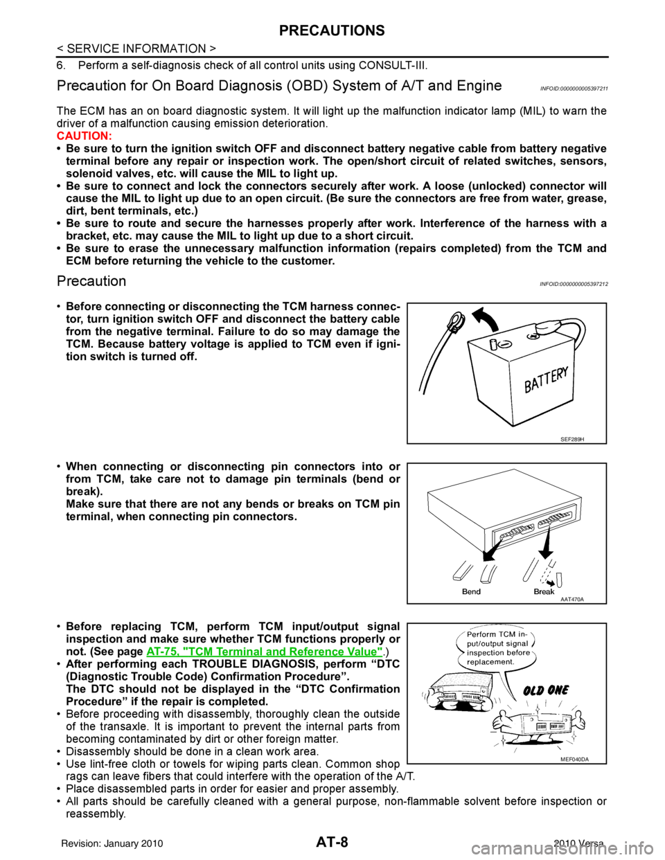
•Before connecting or disconn ecting the TCM harness connec-
tor, turn ignition switch OF F and disconnect the battery cable
from the negative terminal. Failure to do so may damage the
TCM. Because battery voltage is applied to TCM even if igni-
tion switch is turned off.
• When connecting or disconnect ing pin connectors into or
from TCM, take care not to damage pin terminals (bend or
break).
Make sure that there are not any bends or breaks on TCM pin
terminal, when connecting pin connectors.
• Before replacing TCM, perform TCM input/output signal
inspection and make sure whether TCM functions properly or
not. (See page AT-75, "
TCM Terminal and Reference Value".)
• After performing each TROUBLE DIAGNOSIS, perform “DTC
(Diagnostic Trouble Code) Confirmation Procedure”.
The DTC should not be displ ayed in the “DTC Confirmation
Procedure” if the repair is completed.
• Before proceeding with disassembly, thoroughly clean the outside of the transaxle. It is important to prevent the internal parts from
becoming contaminated by dirt or other foreign matter.
• Disassembly should be done in a clean work area.
• Use lint-free cloth or towels for wiping parts clean. Common shop rags can leave fibers that could in terfere with the operation of the A/T.
• Place disassembled parts in order for easier and proper assembly.
• All parts should be carefully cleaned with a general purpose, non-flammable solvent before inspection or reassembly.
SEF289H
AAT470A
MEF040DA
Revision: January 20102010 Versa
Page 26 of 3745
PRECAUTIONSAT-9
< SERVICE INFORMATION >
DE
F
G H
I
J
K L
M A
B
AT
N
O P
• Gaskets, seals and O-rings should be replaced any time the A/T is disassembled.
• It is very important to perform func tional tests whenever they are indicated.
• The valve body contains precision parts and requires extreme care when parts are removed and serviced.
Place disassembled valve body parts in order for easier and proper assembly. Care will also prevent springs
and small parts from becoming scattered or lost.
• Properly installed valves, sleeves, plugs, etc. will slide along bores in valve body under their own weight.
• Before assembly, apply a coat of recommended ATF to all parts. Apply petroleum jelly to protect O-rings and seals, or hold bearings and washers in pl ace during assembly. Do not use grease.
• Extreme care should be taken to avoid damage to O-rings, seals and gaskets when assembling.
• Clean or replace ATF cooler if excessive foreign material is found in oil pan or clogging strainer. Refer to AT-
18, "A/T Fluid Cooler Cleaning".
• After overhaul, refill the A/T with new ATF.
• When the A/T drain plug is removed, only some of the fluid is drained. Old A/T fluid will remain in torque con- verter and ATF cooling system.
Always follow the procedures under “Changing A/T Fluid” in the AT section when changing A/T fluid. Refer to
AT-17, "
Changing A/T Fluid", AT-17, "Checking A/T Fluid".
Service Notice or PrecautionINFOID:0000000005397213
ATF COOLER SERVICE
If A/T fluid contains frictional material (clutches, bands, etc.), or if an A/T is repaired, overhauled, or replaced,
inspect and clean the A/T oil cooler mounted in the radiator or replace the radiator. Flush cooler lines using
cleaning solvent and compressed air after repair. Check Service Bulletins for latest A/T oil cooler cleaning pro-
cedure. For radiator replacement, refer to CO-17, "
Removal and Installation" (HR16DE engine models), CO-
41, "Removal and Installation" (MR18DE engine models).
TORQUE CONVERTER SERVICE
The torque converter should be replaced under any of the following conditions:
• External leaks in the hub weld area.
• Converter hub is scored or damaged.
• Converter pilot is broken, damaged or fits poorly into crankshaft.
• Steel particles are found after flushing the cooler and cooler lines.
• Pump is damaged or steel particles are found in the converter.
• Vehicle has TCC shudder and/or no TCC apply. Replace only after all hydraulic and electrical diagnoses
have been made. (Converter clutch material may be glazed.)
• Converter is contaminated with engi ne coolant containing antifreeze.
• Internal malfunction of stator roller clutch.
• Heavy clutch debris due to overheating (blue converter).
• Steel particles or clutch lining material found in flui d filter or on magnet when no internal parts in unit are
worn or damaged — indicates that lining material came from converter.
The torque converter should not be replaced if:
• The fluid has an odor, is discolored, and there is no evidence of metal or clutch facing particles.
• The threads in one or more of the converter bolt holes are damaged.
• A/T malfunction did not display evidence of damaged or worn internal parts, steel particles or clutch plate lin-
ing material in unit and inside the fluid filter.
• Vehicle has been exposed to high mileage (only). The e xception may be where the torque converter clutch
dampener plate lining has seen excess wear by vehicles operated in heavy and/or constant traffic, such as
taxi, delivery or police use.
OBD-II SELF-DIAGNOSIS
• A/T self-diagnosis is performed by the TCM in combination with the ECM. The results can be read through the blinking pattern of the OD OFF indicator lamp or the malfunction indicator lamp (MIL). Refer to the table
on AT-82, "
Diagnosis Procedure without CONSULT-III" for the indicator used to display each self-diagnostic
result.
• The self-diagnostic results indicated by the MIL are automatically stored in both the ECM and TCM memo- ries.
Always perform the procedure “HOW TO ERASE DTC” on AT-39, "
OBD-II Diagnostic Trouble Code
(DTC)" to complete the repair and avoid unnecessary blinking of the MIL.
• The following self-diagnostic items can be detected us ing ECM self-diagnostic results mode* only when the
OD OFF indicator lamp does not indicate any malfunctions.
- Transmission range switch
- A/T 1GR, 2GR, 3GR, or 4GR function
Revision: January 20102010 Versa
Page 35 of 3745
AT-18
< SERVICE INFORMATION >
A/T FLUID
5. Run engine at idle speed for 5 minutes.
6. Check A/T fluid level and condition. Refer to AT-17, "
Checking A/T Fluid".
A/T Fluid Cooler CleaningINFOID:0000000005397218
Whenever the A/T is repaired, overhauled, or replaced, the A/T fluid cooler mounted in the radiator must be
inspected and cleaned.
Metal debris and friction material, if present, can becom e trapped in the A/T fluid cooler. This debris can con-
taminate the newly serviced A/T or, in severe cases, can bloc k or restrict the flow of A/T fluid. In either case,
malfunction of the newly serviced A/T may result.
Debris, if present, may build up as A/T fluid enters the c ooler inlet. It will be necessary to back flush the cooler
through the cooler outlet in order to flush out any built up debris.
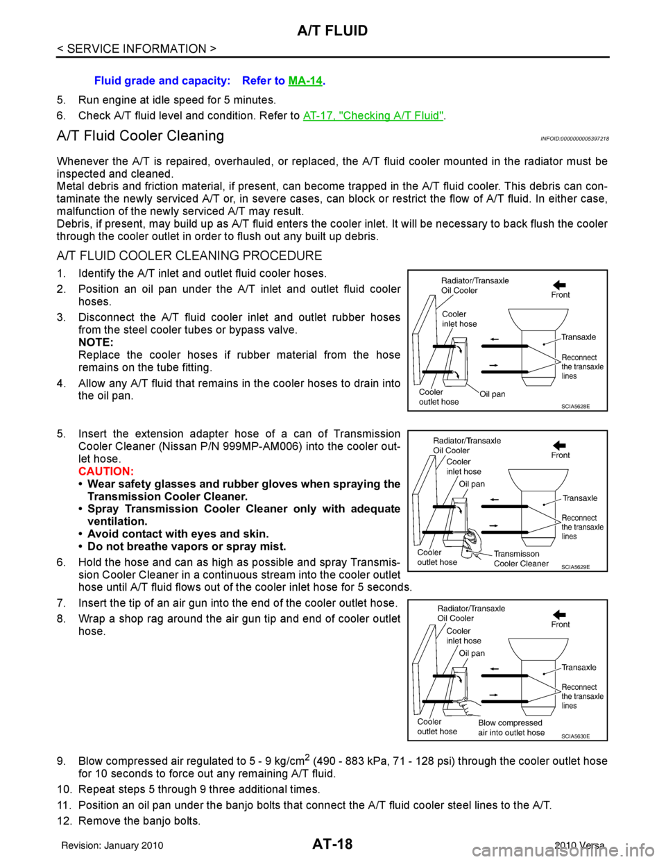
A/T FLUID COOLER CLEANING PROCEDURE
1. Identify the A/T inlet and outlet fluid cooler hoses.
2. Position an oil pan under the A/T inlet and outlet fluid cooler hoses.
3. Disconnect the A/T fluid cooler inlet and outlet rubber hoses from the steel cooler tubes or bypass valve.
NOTE:
Replace the cooler hoses if rubber material from the hose
remains on the tube fitting.
4. Allow any A/T fluid that remains in the cooler hoses to drain into the oil pan.
5. Insert the extension adapter hose of a can of Transmission
Cooler Cleaner (Nissan P/N 999MP-AM006) into the cooler out-
let hose.
CAUTION:
• Wear safety glasses and rubber gloves when spraying the Transmission Cooler Cleaner.
• Spray Transmission Cooler Cleaner only with adequate
ventilation.
• Avoid contact with eyes and skin.
• Do not breathe vapors or spray mist.
6. Hold the hose and can as high as possible and spray Transmis- sion Cooler Cleaner in a continuous stream into the cooler outlet
hose until A/T fluid flows out of t he cooler inlet hose for 5 seconds.
7. Insert the tip of an air gun into the end of the cooler outlet hose.
8. Wrap a shop rag around the air gun tip and end of cooler outlet hose.
9. Blow compressed air regulated to 5 - 9 kg/cm
2 (490 - 883 kPa, 71 - 128 psi) through the cooler outlet hose
for 10 seconds to force out any remaining A/T fluid.
10. Repeat steps 5 through 9 three additional times.
11. Position an oil pan under the banjo bolts that connec t the A/T fluid cooler steel lines to the A/T.
12. Remove the banjo bolts. Fluid grade and capacity: Refer to
MA-14
.
SCIA5628E
SCIA5629E
SCIA5630E
Revision: January 20102010 Versa