Ignition signal wiring diagram NISSAN TIIDA 2010 Service Repair Manual
[x] Cancel search | Manufacturer: NISSAN, Model Year: 2010, Model line: TIIDA, Model: NISSAN TIIDA 2010Pages: 3745, PDF Size: 73.67 MB
Page 119 of 3745
AT-102
< SERVICE INFORMATION >
P0720 OUTPUT SPEED SENSOR
TCM TERMINALS AND REFERENCE VALUES
Refer to AT-75, "TCM Terminal and Reference Value".
Diagnosis ProcedureINFOID:0000000005397281
1.CHECK INPUT SIGNAL
With CONSULT-III
1. Start engine.
2. Select “TCM INPUT SIGNALS” in “DATA MONITOR” mode for “TRANSMISSION” with CONSULT-III.
3. Read out the value of “VHCL/S SE-A/T” while driving. Check the value changes according to driving speed.
OK or NG
OK >> GO TO 8.
NG >> GO TO 2.
2. CHECK OUTPUT SPEED SENSOR
With CONSULT-III
1. Start engine.
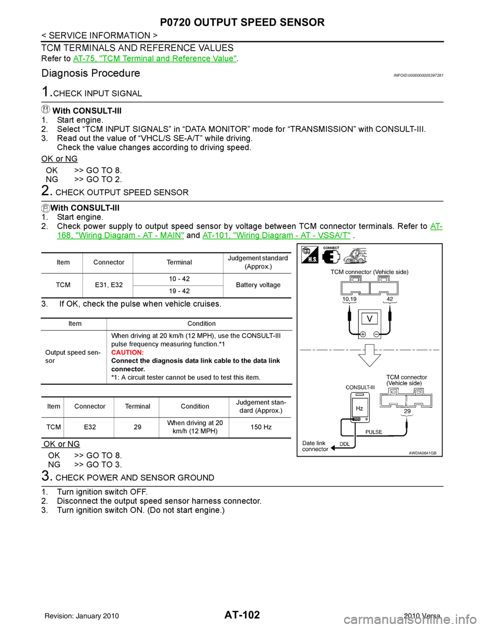
2. Check power supply to output speed sensor by voltage between TCM connector terminals. Refer to AT-
168, "Wiring Diagram - AT - MAIN" and AT-101, "Wiring Diagram - AT - VSSA/T" .
3. If OK, check the pulse when vehicle cruises.
OK or NG
OK >> GO TO 8.
NG >> GO TO 3.
3. CHECK POWER AND SENSOR GROUND
1. Turn ignition switch OFF.
2. Disconnect the output speed sensor harness connector.
3. Turn ignition switch ON. (Do not start engine.)
Item Connector TerminalJudgement standard
(Approx.)
TCM E31, E32 10 - 42
Battery voltage
19 - 42
Item Condition
Output speed sen-
sor When driving at 20 km/h (12 MPH), use the CONSULT-III
pulse frequency measuring function.*1
CAUTION:
Connect the diagnosis
data link cable to the data link
connector.
*1: A circuit tester cannot be used to test this item.
Item Connector Terminal Condition Judgement stan-
dard (Approx.)
TCM E32 29When driving at 20
km/h (12 MPH) 150 Hz
AWDIA0641GB
Revision: January 20102010 Versa
Page 181 of 3745
AT-164
< SERVICE INFORMATION >
INPUT SPEED SENSOR A
Diagnosis Procedure
INFOID:0000000005397377
1.CHECK INPUT SIGNAL
With CONSULT-III
1. Start engine.
2. Select “TCM INPUT SIGNALS” in “DATA MONITOR” mode for “TRANSMISSION” with CONSULT-III.
3. Read out the value of “INPUT SPEED” while driving. Check the value changes according to driving speed.
OK or NG
OK >> GO TO 8.
NG >> GO TO 2.
2. CHECK INPUT SPEED SENSOR
With CONSULT-III
1. Start engine.
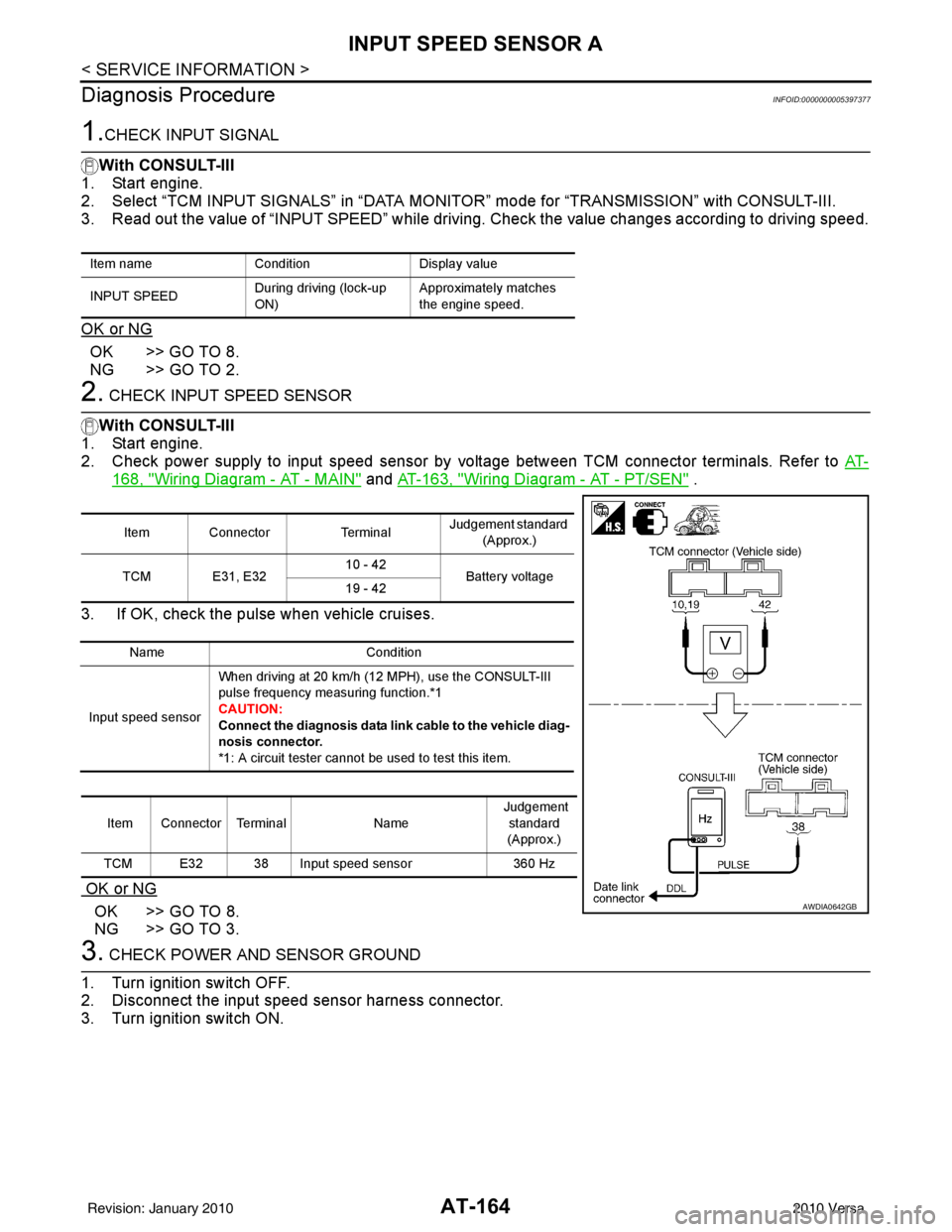
2. Check power supply to input speed sensor by voltage between TCM connector terminals. Refer to AT-
168, "Wiring Diagram - AT - MAIN" and AT-163, "Wiring Diagram - AT - PT/SEN" .
3. If OK, check the pulse when vehicle cruises.
OK or NG
OK >> GO TO 8.
NG >> GO TO 3.
3. CHECK POWER AND SENSOR GROUND
1. Turn ignition switch OFF.
2. Disconnect the input speed sensor harness connector.
3. Turn ignition switch ON.
Item name ConditionDisplay value
INPUT SPEED During driving (lock-up
ON)Approximately matches
the engine speed.
Item Connector
TerminalJudgement standard
(Approx.)
TCM E31, E32 10 - 42
Battery voltage
19 - 42
Name Condition
Input speed sensor When driving at 20 km/h (12 MPH), use the CONSULT-III
pulse frequency measuring function.*1
CAUTION:
Connect the diagnosis data link
cable to the vehicle diag-
nosis connector.
*1: A circuit tester cannot be used to test this item.
Item Connector Terminal Name Judgement
standard
(Approx.)
TCM E32 38 Input speed sensor 360 Hz
AWDIA0642GB
Revision: January 20102010 Versa
Page 189 of 3745
AT-172
< SERVICE INFORMATION >
TR SW, OD SW AND CLOSED THROTTLE, WIDE OPEN THROTTLE POSITION
SIGNAL CIRCUIT
2.CHECK TRANSMISSION RANGE SWITCH CIRCUIT
With CONSULT-III
1. Turn ignition switch ON. (Do not start engine.)
2. Select “TCM INPUT SIGNALS” in “DATA MONITOR” mode for “TRANSMISSION” with CONSULT-III.
3. Read out “P·N”, “R”, “D”, “2” and “1” position switches moving selector lever to each position.
OK or NG
OK >> GO TO 4.
NG >> Check transmission range switch circuit. Refer to AT- 9 0
.
3.CHECK TRANSMISSION RANGE SWITCH CIRCUIT
Without CONSULT-III
1. Turn ignition switch ON. (Do not start engine.)
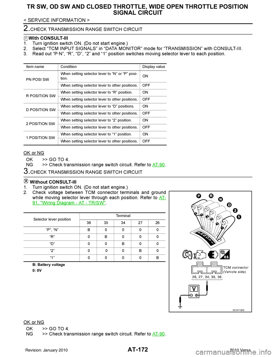
2. Check voltage between TCM connector terminals and ground while moving selector lever through each position. Refer to AT-
91, "Wiring Diagram - AT - TR/SW".
B: Battery voltage
0: 0V
OK or NG
OK >> GO TO 4.
NG >> Check transmission range switch circuit. Refer to AT- 9 0
.
Item name Condition Display value
PN POSI SW When setting selector le
ver to “N” or “P” posi-
tion. ON
When setting selector lever to other positions. OFF
R POSITION SW When setting selector lever to “R” position. ON
When setting selector lever to other positions. OFF
D POSITION SW When setting selector lever to “D” positions. ON
When setting selector lever to other positions. OFF
2 POSITION SW When setting selector lever to “2” position. ON
When setting selector lever to other positions. OFF
1 POSITION SW When setting selector lever to “1” position. ON
When setting selector lever to other positions. OFF
Selector lever position Te r m i n a l
36 35 34 27 26
“P”, “N” B0000 “R” 0B000
“D” 0 0 B 0 0
“2” 0 0 0 B 0
“1” 0000B
SCIA7162E
Revision: January 20102010 Versa
Page 191 of 3745
AT-174
< SERVICE INFORMATION >
TR SW, OD SW AND CLOSED THROTTLE, WIDE OPEN THROTTLE POSITION
SIGNAL CIRCUIT
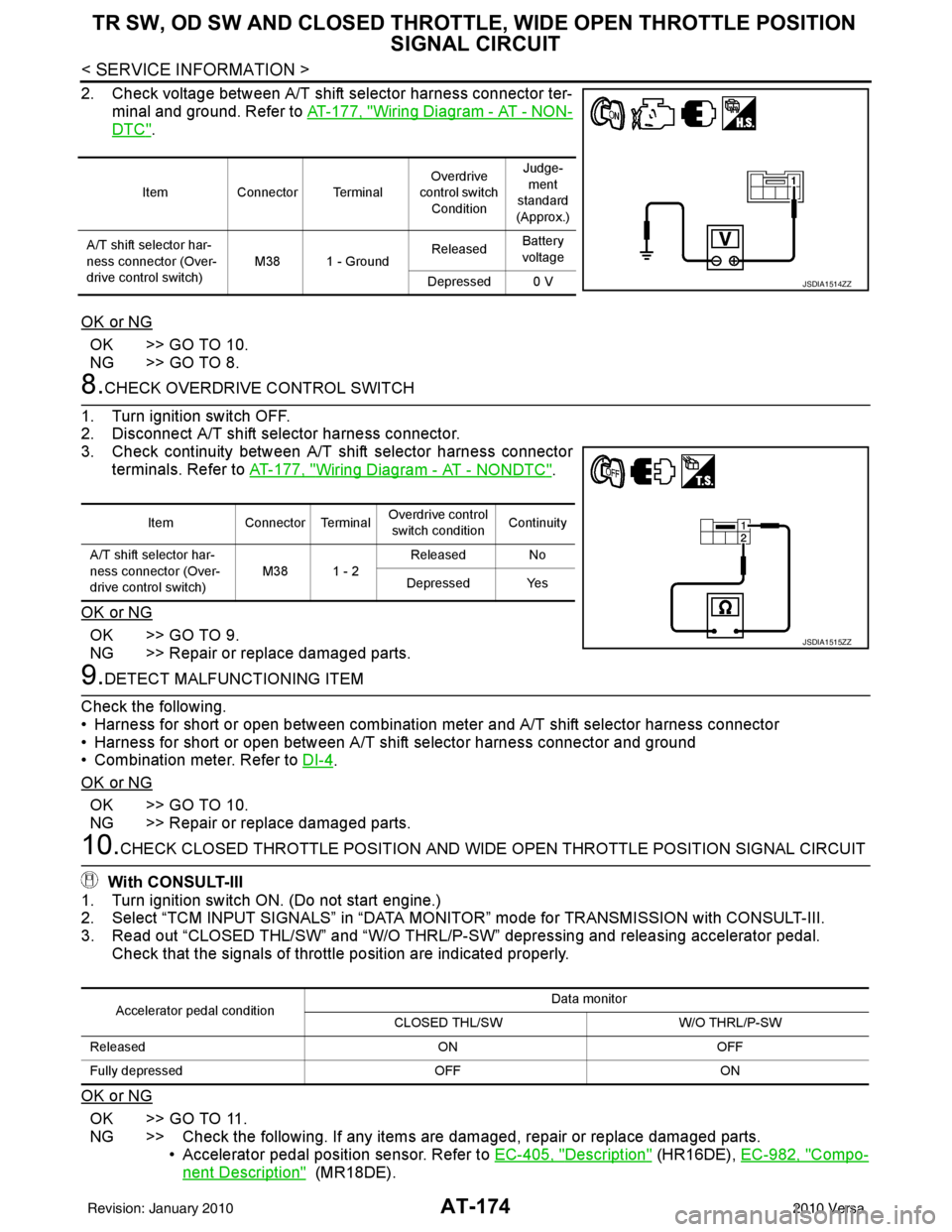
2. Check voltage between A/T shift selector harness connector ter-
minal and ground. Refer to AT-177, "
Wiring Diagram - AT - NON-
DTC".
OK or NG
OK >> GO TO 10.
NG >> GO TO 8.
8.CHECK OVERDRIVE CONTROL SWITCH
1. Turn ignition switch OFF.
2. Disconnect A/T shift selector harness connector.
3. Check continuity between A/T shift selector harness connector terminals. Refer to AT-177, "
Wiring Diagram - AT - NONDTC".
OK or NG
OK >> GO TO 9.
NG >> Repair or replace damaged parts.
9.DETECT MALFUNCTIONING ITEM
Check the following.
• Harness for short or open between combination meter and A/T shift selector harness connector
• Harness for short or open between A/T shift selector harness connector and ground
• Combination meter. Refer to DI-4
.
OK or NG
OK >> GO TO 10.
NG >> Repair or replace damaged parts.
10.CHECK CLOSED THROTTLE POSI TION AND WIDE OPEN THROTTLE POSITION SIGNAL CIRCUIT
With CONSULT-III
1. Turn ignition switch ON. (Do not start engine.)
2. Select “TCM INPUT SIGNALS” in “DATA MONITOR” mode for TRANSMISSION with CONSULT-III.
3. Read out “CLOSED THL/SW” and “W/O THRL/P-S W” depressing and releasing accelerator pedal.
Check that the signals of throttle position are indicated properly.
OK or NG
OK >> GO TO 11.
NG >> Check the following. If any items are damaged, repair or replace damaged parts. • Accelerator pedal position sensor. Refer to EC-405, "
Description" (HR16DE), EC-982, "Compo-
nent Description" (MR18DE).
Item Connector Terminal Overdrive
control switch
Condition Judge-
ment
standard
(Approx.)
A/T shift selector har-
ness connector (Over-
drive control switch) M38 1 - Ground
Released
Battery
voltage
Depressed 0 V
JSDIA1514ZZ
Item Connector Terminal Overdrive control
switch condition Continuity
A/T shift selector har-
ness connector (Over-
drive control switch) M38 1 - 2
Released No
Depressed Yes
JSDIA1515ZZ
Accelerator pedal condition Data monitor
CLOSED THL/SW W/O THRL/P-SW
Released ONOFF
Fully depressed OFFON
Revision: January 20102010 Versa
Page 214 of 3745
TROUBLE DIAGNOSIS FOR SYMPTOMSAT-197
< SERVICE INFORMATION >
DE
F
G H
I
J
K L
M A
B
AT
N
O P
OK or NG
OK >> GO TO 6.
NG >> Repair or replace damaged parts.
6.CHECK SYMPTOM
Check again. Refer to AT-58, "
Cruise Test - Part 1" .
OK or NG
OK >> INSPECTION END
NG >> GO TO 7.
7.CHECK TCM
1. Check TCM input/output signals. Refer to AT-75, "
TCM Terminal and Reference Value" .
2. If NG, recheck TCM pin terminals for dam age or loose connection with harness connector.
OK or NG
OK >> INSPECTION END
NG >> Repair or replace damaged parts.
A/T Does Not Shift: D4→ D3, When OD OFFINFOID:0000000005397408
SYMPTOM:
A/T does not shift from D4 to D3 when OD OFF (OD OFF indicator lamp is on) on “Cruise Test — Part
3”.
DIAGNOSTIC PROCEDURE
1.CHECK CAN COMMUNICATION LINE
Perform self-diagnosis. Refer to AT-77, "
CONSULT-III Function (TRANSMISSION)" or AT-82, "Diagnosis Pro-
cedure without CONSULT-III" .
Is a malfunction in CAN communication indicated in the results?
YES >> Check CAN communication line. Refer to AT- 8 7 .
NO >> GO TO 2.
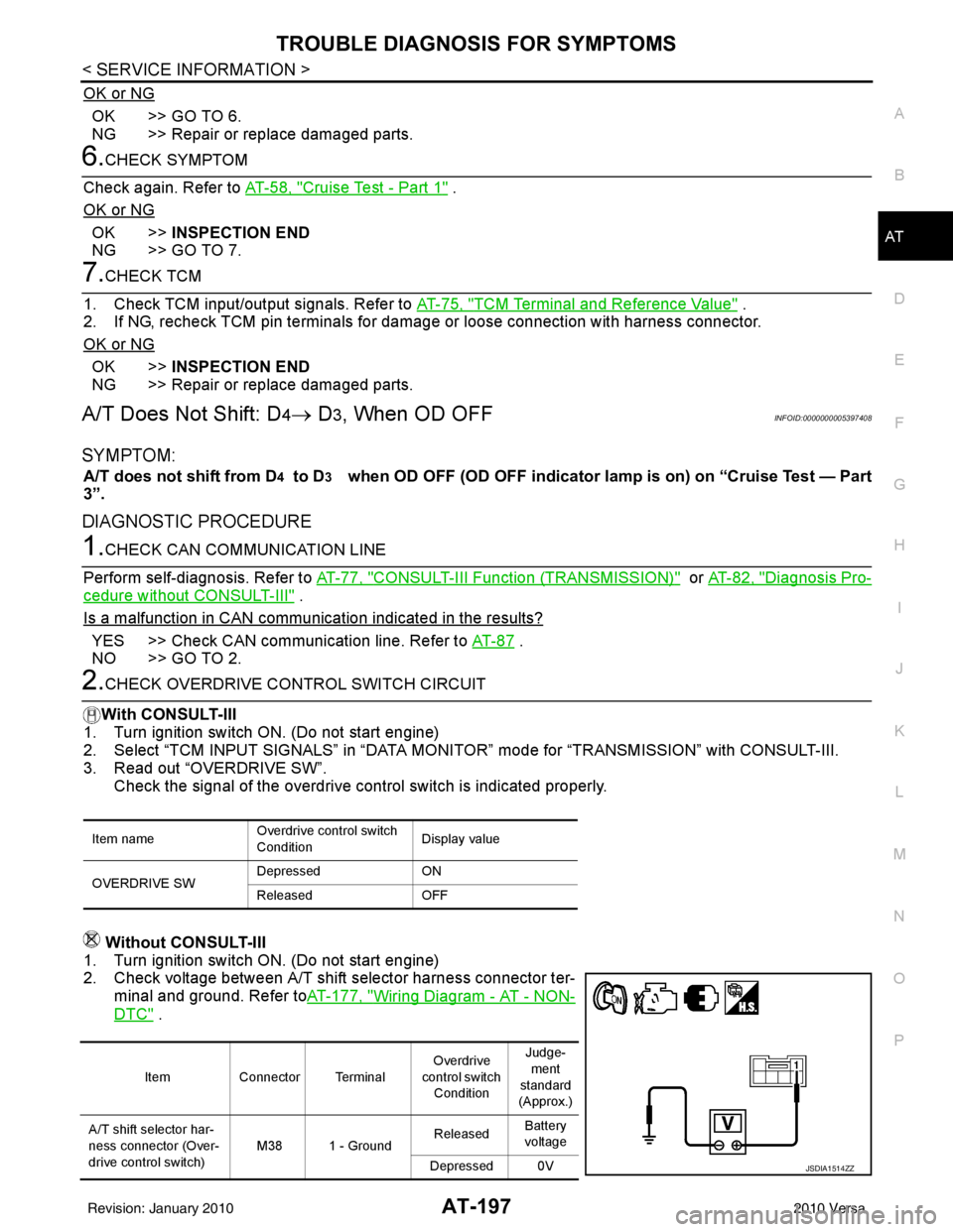
2.CHECK OVERDRIVE CO NTROL SWITCH CIRCUIT
With CONSULT-III
1. Turn ignition switch ON. (Do not start engine)
2. Select “TCM INPUT SIGNALS” in “DATA MONI TOR” mode for “TRANSMISSION” with CONSULT-III.
3. Read out “OVERDRIVE SW”. Check the signal of the overdrive control switch is indicated properly.
Without CONSULT-III
1. Turn ignition switch ON. (Do not start engine)
2. Check voltage between A/T shift selector harness connector ter- minal and ground. Refer to AT-177, "
Wiring Diagram - AT - NON-
DTC" .
Item name Overdrive control switch
ConditionDisplay value
OVERDRIVE SW Depressed
ON
Released OFF
ItemConnector Terminal Overdrive
control switch Condition Judge-
ment
standard
(Approx.)
A/T shift selector har-
ness connector (Over-
drive control switch) M38 1 - Ground
Released
Battery
voltage
Depressed 0V
JSDIA1514ZZ
Revision: January 20102010 Versa
Page 216 of 3745
TROUBLE DIAGNOSIS FOR SYMPTOMSAT-199
< SERVICE INFORMATION >
DE
F
G H
I
J
K L
M A
B
AT
N
O P
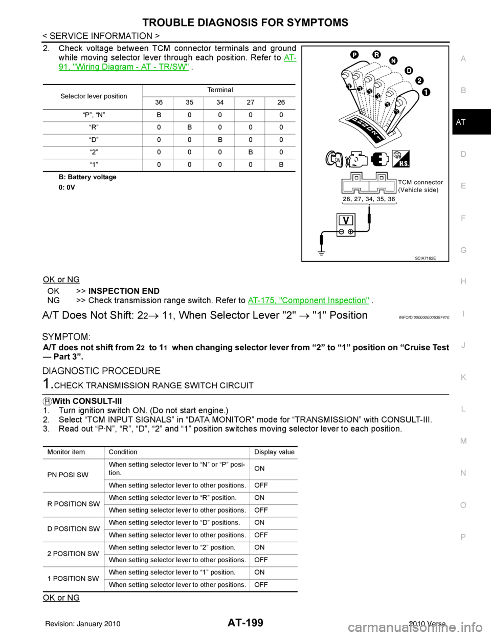
2. Check voltage between TCM connector terminals and ground while moving selector lever through each position. Refer to AT-
91, "Wiring Diagram - AT - TR/SW" .
B: Battery voltage
0: 0V
OK or NG
OK >>INSPECTION END
NG >> Check transmission range switch. Refer to AT-175, "
Component Inspection" .
A/T Does Not Shift: 22→ 11, When Selector Lever "2" → "1" PositionINFOID:0000000005397410
SYMPTOM:
A/T does not shift from 22 to 11 when changing selector lever from “2” to “1” position on “Cruise Test
— Part 3”.
DIAGNOSTIC PROCEDURE
1.CHECK TRANSMISSION RANGE SWITCH CIRCUIT
With CONSULT-III
1. Turn ignition switch ON. (Do not start engine.)
2. Select “TCM INPUT SIGNALS” in “DATA MONI TOR” mode for “TRANSMISSION” with CONSULT-III.
3. Read out “P·N”, “R”, “D”, “2” and “1” position switches moving selector lever to each position.
OK or NG
Selector lever position Te r m i n a l
36 35 34 27 26
“P”, “N” B 0 0 0 0
“R” 0B000
“D” 0 0 B 0 0
“2” 0 0 0 B 0
“1” 0 0 0 0 B
SCIA7162E
Monitor item Condition Display value
PN POSI SW When setting selector le
ver to “N” or “P” posi-
tion. ON
When setting selector lever to other positions. OFF
R POSITION SW When setting selector lever to “R” position. ON
When setting selector lever to other positions. OFF
D POSITION SW When setting selector lever to “D” positions. ON
When setting selector lever to other positions. OFF
2 POSITION SW When setting selector lever to “2” position. ON
When setting selector lever to other positions. OFF
1 POSITION SW When setting selector lever to “1” position. ON
When setting selector lever to other positions. OFF
Revision: January 20102010 Versa
Page 217 of 3745
AT-200
< SERVICE INFORMATION >
TROUBLE DIAGNOSIS FOR SYMPTOMS
OK >> GO TO 3
NG >> Check transmission range switch. Refer to AT-175, "
Component Inspection" .
2.CHECK TRANSMISSION RANGE SWITCH CIRCUIT
Without CONSULT-III
1. Turn ignition switch ON. (Do not start engine.)
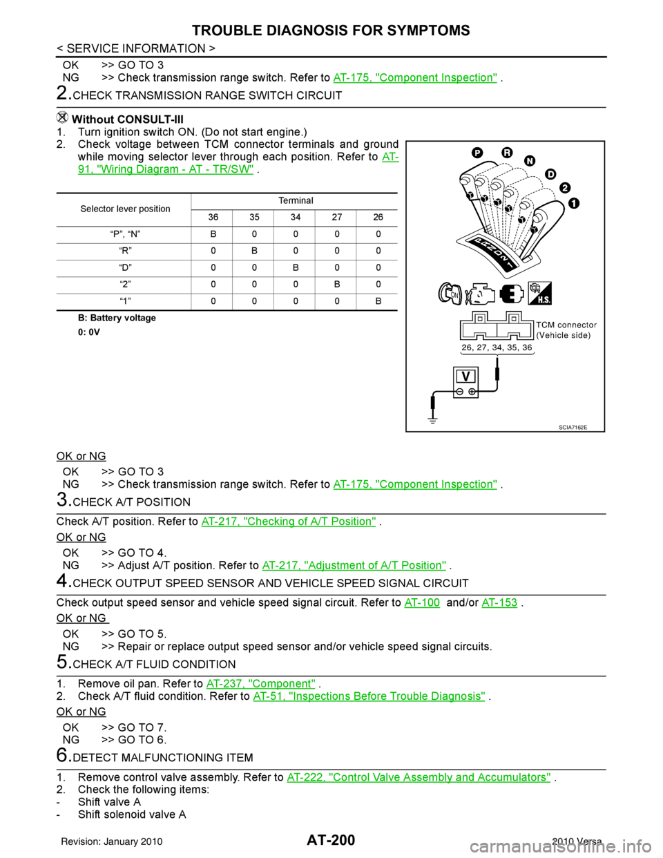
2. Check voltage between TCM connector terminals and ground
while moving selector lever through each position. Refer to AT-
91, "Wiring Diagram - AT - TR/SW" .
B: Battery voltage
0: 0V
OK or NG
OK >> GO TO 3
NG >> Check transmission range switch. Refer to AT-175, "
Component Inspection" .
3.CHECK A/T POSITION
Check A/T position. Refer to AT-217, "
Checking of A/T Position" .
OK or NG
OK >> GO TO 4.
NG >> Adjust A/T position. Refer to AT-217, "
Adjustment of A/T Position" .
4.CHECK OUTPUT SPEED SENSOR AND VEHICLE SPEED SIGNAL CIRCUIT
Check output speed sensor and vehicle speed signal circuit. Refer to AT-100
and/or AT-153 .
OK or NG
OK >> GO TO 5.
NG >> Repair or replace output speed sens or and/or vehicle speed signal circuits.
5.CHECK A/T FLUID CONDITION
1. Remove oil pan. Refer to AT-237, "
Component" .
2. Check A/T fluid condition. Refer to AT-51, "
Inspections Before Trouble Diagnosis" .
OK or NG
OK >> GO TO 7.
NG >> GO TO 6.
6.DETECT MALFUNCTIONING ITEM
1. Remove control valve assembly. Refer to AT-222, "
Control Valve Assembly and Accumulators" .
2. Check the following items:
- Shift valve A
- Shift solenoid valve A
Selector lever position Te r m i n a l
36 35 34 27 26
“P”, “N” B0000 “R” 0B000
“D” 0 0 B 0 0
“2” 000B0
“1” 0000B
SCIA7162E
Revision: January 20102010 Versa
Page 219 of 3745
AT-202
< SERVICE INFORMATION >
TROUBLE DIAGNOSIS FOR SYMPTOMS
Without CONSULT-III
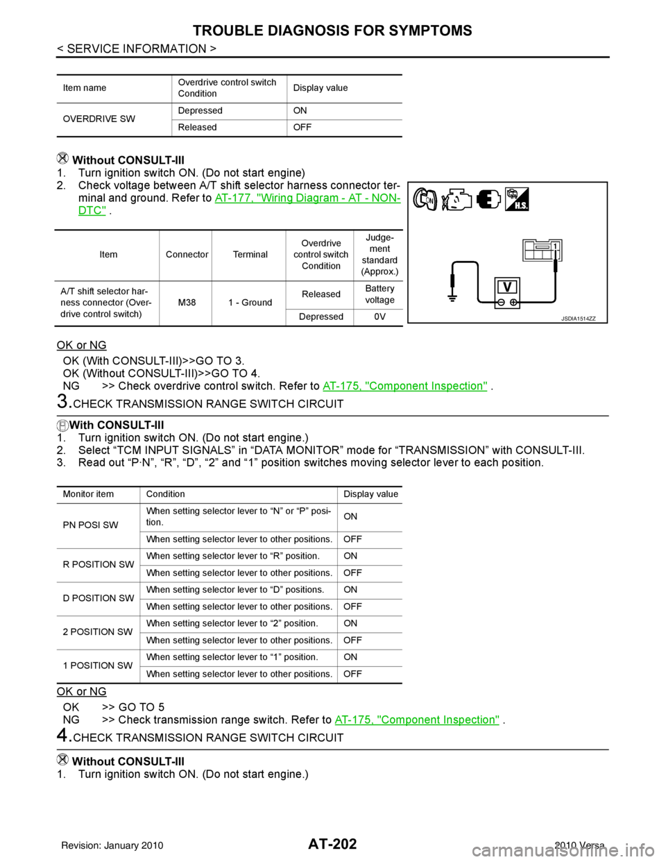
1. Turn ignition switch ON. (Do not start engine)
2. Check voltage between A/T shift selector harness connector ter-
minal and ground. Refer to AT-177, "
Wiring Diagram - AT - NON-
DTC" .
OK or NG
OK (With CONSULT-III)>>GO TO 3.
OK (Without CONSULT-III)>>GO TO 4.
NG >> Check overdrive control switch. Refer to AT-175, "
Component Inspection" .
3.CHECK TRANSMISSION RANGE SWITCH CIRCUIT
With CONSULT-III
1. Turn ignition switch ON. (Do not start engine.)
2. Select “TCM INPUT SIGNALS” in “DATA MONITOR” mode for “TRANSMISSION” with CONSULT-III.
3. Read out “P·N”, “R”, “D”, “2” and “1” position switches moving selector lever to each position.
OK or NG
OK >> GO TO 5
NG >> Check transmission range switch. Refer to AT-175, "
Component Inspection" .
4.CHECK TRANSMISSION RANGE SWITCH CIRCUIT
Without CONSULT-III
1. Turn ignition switch ON. (Do not start engine.)
Item name Overdrive control switch
ConditionDisplay value
OVERDRIVE SW Depressed
ON
Released OFF
ItemConnector Terminal Overdrive
control switch
Condition Judge-
ment
standard
(Approx.)
A/T shift selector har-
ness connector (Over-
drive control switch) M38 1 - Ground
Released
Battery
voltage
Depressed 0V
JSDIA1514ZZ
Monitor item Condition Display value
PN POSI SW When setting selector le
ver to “N” or “P” posi-
tion. ON
When setting selector lever to other positions. OFF
R POSITION SW When setting selector lever to “R” position. ON
When setting selector lever to other positions. OFF
D POSITION SW When setting selector lever to “D” positions. ON
When setting selector lever to other positions. OFF
2 POSITION SW When setting selector lever to “2” position. ON
When setting selector lever to other positions. OFF
1 POSITION SW When setting selector lever to “1” position. ON
When setting selector lever to other positions. OFF
Revision: January 20102010 Versa
Page 892 of 3745

BRC-2
SYSTEM DESCRIPTION ................................ ...43
System Component ............................................. ...43
ABS Function ....................................... ...................43
EBD Function ...................................................... ...43
TCS Function ..........................................................44
VDC Function .........................................................44
Wheel Sensors .......................................................44
Fail-Safe Function ..................................................44
Hydraulic Circuit Diagram .......................................45
CAN COMMUNICATION ...................................46
System Description .................................................46
TROUBLE DIAGNOSIS .....................................47
How to Perform Trouble Diagnosis for Quick and
Accurate Repair ................................................... ...
47
Component Parts and Harness Connector Loca-
tion ..........................................................................
50
Schematic ...............................................................51
Wiring Diagram - VDC - ..........................................52
Basic Inspection .....................................................56
Warning Lamp and Indicator Timing .......................57
Control Unit Input/Output Signal Standard .............57
CONSULT-III Function (ABS) .................................60
TROUBLE DIAGNOSIS FOR SELF-DIAG-
NOSTIC ITEMS ............................................... ...
67
Wheel Sensor System Inspection ...........................67
Engine System Inspection ................................... ...68
ABS/TCS/VDC Control Unit Inspection ..................68
Steering Angle Sensor System Inspection .......... ...69
Yaw Rate/Side/Decel G Sensor System Inspec-
tion ....................................................................... ...
70
Solenoid and VDC Change-Over Valve System
Inspection ...............................................................
72
Actuator Motor, Motor Relay, and Circuit Inspec-
tion ....................................................................... ...
73
Stop Lamp Switch System Inspection ....................74
ABS/TCS/VDC Control Unit Power and Ground
Systems Inspection .............................................. ...
75
Brake Fluid Level Switch System Inspection ..........76
Pressure Sensor System Inspection .......................77
Transmission Range Switch System Inspection .. ...78
CAN Communication System Inspection ................79
Component Inspection ............................................79
TROUBLE DIAGNOSES FOR SYMPTOMS .....81
ABS Works Frequently ............................................81
Unexpected Pedal Action ..................................... ...81
Long Stopping Distance ..........................................82
ABS Does Not Work ...............................................82
Pedal Vibration or ABS Op eration Noise ................82
ABS Warning Lamp Does Not Come On When Ig-
nition Switch Is Turned On ................................... ...
83
ABS Warning Lamp Stays On When Ignition
Switch Is Turned On ............................................ ...
83
Vehicle Jerks During TCS/VDC Activation ..............84
ON-VEHICLE SERVICE ....................................85
Adjustment of Steering Angle Sensor Neutral Po-
sition ..................................................................... ...
85
WHEEL SENSORS ............................................86
Removal and Installation .........................................86
SENSOR ROTOR ........................................... ...88
Removal and Installation .........................................88
ACTUATOR AND ELECTRIC UNIT (ASSEM-
BLY) ................................................................ ...
89
Removal and Installation .........................................89
STEERING ANGLE SENSOR ........................ ...91
Removal and Installation .........................................91
G SENSOR ........................................................92
Removal and Installation .........................................92
Revision: January 20102010 Versa
Page 1211 of 3745

DI-1
ELECTRICAL
C
DE
F
G H
I
J
L
M
SECTION DI
A
B
DI
N
O P
CONTENTS
DRIVER INFORMATION SYSTEM
SERVICE INFORMATION .. ..........................2
PRECAUTION ................................................ .....2
Precaution for Supplemental Restraint System
(SRS) "AIR BAG" and "SEAT BELT PRE-TEN-
SIONER" ............................................................. ......
2
Precaution Necessary for Steering Wheel Rota-
tion After Battery Disconnect ............................... ......
2
COMBINATION METERS ...................................4
Component Parts and Harness Connector Loca-
tion ...................................................................... ......
4
System Description ...................................................4
Arrangement of Combination Meter ..........................6
Internal Circuit ...........................................................7
Wiring Diagram - METER - .......................................8
Combination Meter Harness Connector Terminal
Layout .....................................................................
10
Terminal and Reference Value for Combination
Meter .......................................................................
10
Self-Diagnosis Mode of Combination Meter ........ ....11
CONSULT-III Function (METER/M&A) ............... ....13
Trouble Diagnosis ...................................................14
Symptom Chart .......................................................15
Power Supply and Ground Circuit Inspection .........15
Vehicle Speed Signal Inspection .............................16
Engine Speed Signal Inspection .............................17
Fuel Level Sensor Signal Inspection .......................17
Fuel Gauge Fluctuates, Indicates Wrong Value, or
Varies ......................................................................
19
Fuel Gauge Does Not Move to Full-position ...........19
DTC [U1000] CAN Communication Circuit ......... ....19
Electrical Component Inspection .............................20
Removal and Installation .........................................20
WARNING LAMPS ......................................... ....21
Schematic ........................................................... ....21
Wiring Diagram - WARN - ................................... ....22
Oil Pressure Warning Lamp Stays Off (Ignition
Switch ON) .......................................................... ....
30
Oil Pressure Warning Lamp Does Not Turn Off
(Oil Pressure Is Normal) ...................................... ....
32
Component Inspection .............................................32
A/T INDICATOR ................................................34
System Description ..................................................34
Wiring Diagram - AT/IND - .......................................35
A/T Indicator Does Not Illuminate ............................36
CVT INDICATOR ...............................................38
System Description ..................................................38
Schematic ................................................................38
Wiring Diagram - CVTIND - .....................................39
CVT Indicator Does Not Illuminate ..........................41
WARNING CHIME .............................................43
Component Parts and Harness Connector Loca-
tion ....................................................................... ....
43
System Description ..................................................43
Wiring Diagram - CHIME - .......................................46
Terminal and Reference Value for BCM ..................47
CONSULT-III Function (B CM) .................................47
Trouble Diagnosis ................................................ ....48
Combination Meter Buzzer Circuit Inspection .........49
Front Door Switch LH Signal Inspection .............. ....50
Key Switch Signal Inspection (Without Intelligent
Key) ..................................................................... ....
51
Key Switch and Ignition Knob Switch Signal In-
spection (With Intelligent Key, When Mechanical
Key Is Used) ........................................................ ....
52
Lighting Switch Signal Inspection ............................54
Parking Brake Switch Signal Inspection ..................54
Electrical Component Inspection .............................55
Revision: January 20102010 Versa