PG-4 NISSAN TIIDA 2010 Service Repair Manual
[x] Cancel search | Manufacturer: NISSAN, Model Year: 2010, Model line: TIIDA, Model: NISSAN TIIDA 2010Pages: 3745, PDF Size: 73.67 MB
Page 90 of 3745
TROUBLE DIAGNOSISAT-73
< SERVICE INFORMATION >
DE
F
G H
I
J
K L
M A
B
AT
N
O P
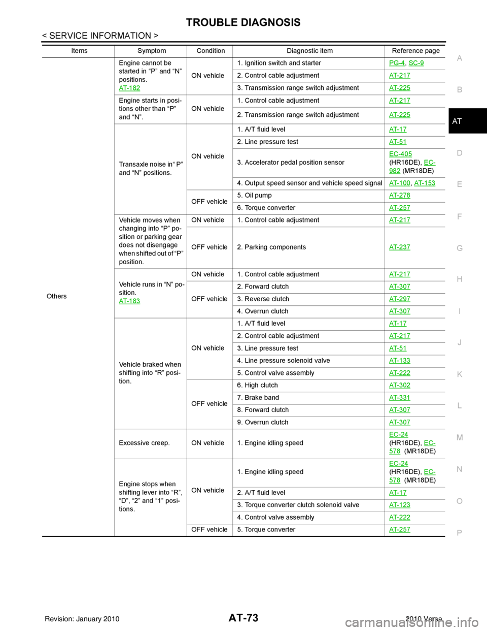
Others Engine cannot be
started in “P” and “N”
positions.
AT- 1 8 2
ON vehicle
1. Ignition switch and starter
PG-4
, SC-9
2. Control cable adjustmentAT- 2 1 7
3. Transmission range switch adjustmentAT- 2 2 5
Engine starts in posi-
tions other than “P”
and “N”.ON vehicle
1. Control cable adjustment
AT- 2 1 7
2. Transmission range switch adjustmentAT- 2 2 5
Transaxle noise in“ P”
and “N” positions.ON vehicle1. A/T fluid level
AT- 1 7
2. Line pressure testAT- 5 1
3. Accelerator pedal position sensorEC-405
(HR16DE), EC-
982 (MR18DE)
4. Output speed sensor and vehicle speed signal AT- 1 0 0
, AT- 1 5 3
OFF vehicle5. Oil pump
AT- 2 7 86. Torque converterAT- 2 5 7
Vehicle moves when
changing into “P” po-
sition or parking gear
does not disengage
when shifted out of “P”
position.ON vehicle 1. Control cable adjustment
AT- 2 1 7
OFF vehicle 2. Parking componentsAT- 2 3 7
Vehicle runs in “N” po-
sition.
AT- 1 8 3
ON vehicle 1. Control cable adjustmentAT- 2 1 7
OFF vehicle2. Forward clutch
AT- 3 0 73. Reverse clutchAT- 2 9 7
4. Overrun clutchAT- 3 0 7
Vehicle braked when
shifting into “R” posi-
tion.ON vehicle
1. A/T fluid level
AT- 1 7
2. Control cable adjustmentAT- 2 1 7
3. Line pressure testAT- 5 1
4. Line pressure solenoid valveAT- 1 3 3
5. Control valve assemblyAT- 2 2 2
OFF vehicle6. High clutch
AT- 3 0 27. Brake band AT- 3 3 1
8. Forward clutchAT- 3 0 7
9. Overrun clutchAT- 3 0 7
Excessive creep. ON vehicle 1. Engine idling speed EC-24
(HR16DE), EC-
578 (MR18DE)
Engine stops when
shifting lever into “R”,
“D”, “2” and “1” posi-
tions. ON vehicle
1. Engine idling speed
EC-24
(HR16DE), EC-
578 (MR18DE)
2. A/T fluid level AT- 1 7
3. Torque converter clutch solenoid valveAT- 1 2 3
4. Control valve assemblyAT- 2 2 2
OFF vehicle 5. Torque converter AT- 2 5 7
ItemsSymptom Condition Diagnostic itemReference page
Revision: January 20102010 Versa
Page 110 of 3745
P0705 TRANSMISSION RANGE SWITCH A
AT-93
< SERVICE INFORMATION >
D E
F
G H
I
J
K L
M A
B
AT
N
O P
NG >> GO TO 3.
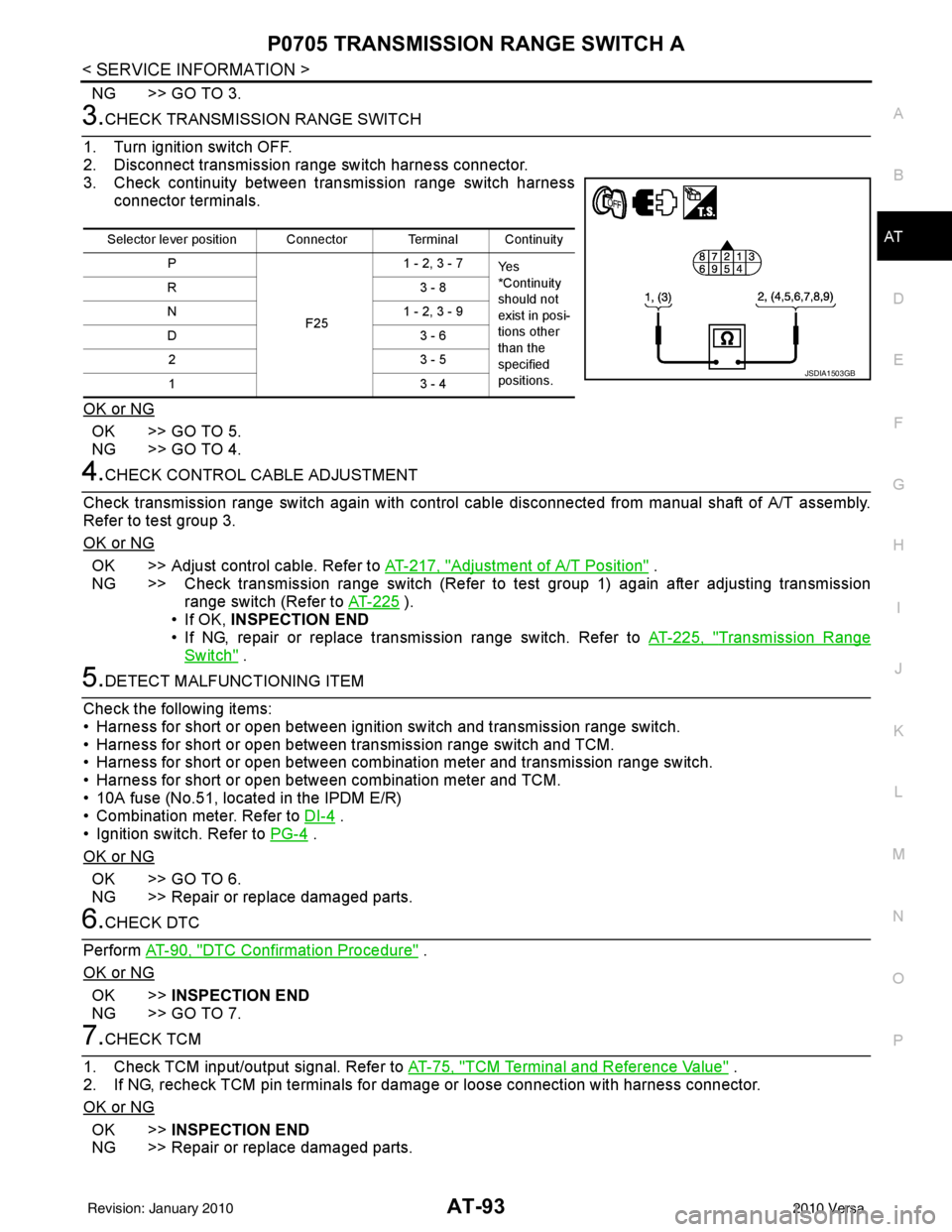
3.CHECK TRANSMISSION RANGE SWITCH
1. Turn ignition switch OFF.
2. Disconnect transmission range switch harness connector.
3. Check continuity between transmission range switch harness connector terminals.
OK or NG
OK >> GO TO 5.
NG >> GO TO 4.
4.CHECK CONTROL CABLE ADJUSTMENT
Check transmission range switch again with control cabl e disconnected from manual shaft of A/T assembly.
Refer to test group 3.
OK or NG
OK >> Adjust control cable. Refer to AT-217, "Adjustment of A/T Position" .
NG >> Check transmission range switch (Refer to test group 1) again after adjusting transmission range switch (Refer to AT-225
).
• If OK, INSPECTION END
• If NG, repair or replace transmission range switch. Refer to AT-225, "
Transmission Range
Switch" .
5.DETECT MALFUNCTIONING ITEM
Check the following items:
• Harness for short or open between ignition switch and transmission range switch.
• Harness for short or open between transmission range switch and TCM.
• Harness for short or open between combination meter and transmission range switch.
• Harness for short or open between combination meter and TCM.
• 10A fuse (No.51, located in the IPDM E/R)
• Combination meter. Refer to DI-4
.
• Ignition switch. Refer to PG-4
.
OK or NG
OK >> GO TO 6.
NG >> Repair or replace damaged parts.
6.CHECK DTC
Perform AT-90, "
DTC Confirmation Procedure" .
OK or NG
OK >> INSPECTION END
NG >> GO TO 7.
7.CHECK TCM
1. Check TCM input/output signal. Refer to AT-75, "
TCM Terminal and Reference Value" .
2. If NG, recheck TCM pin terminals for dam age or loose connection with harness connector.
OK or NG
OK >> INSPECTION END
NG >> Repair or replace damaged parts.
Selector lever position Connector Terminal Continuity
P
F251 - 2, 3 - 7
Ye s
*Continuity
should not
exist in posi-
tions other
than the
specified
positions.
R3
- 8
N 1 - 2, 3 - 9
D3 - 6
23 - 5
13 - 4
JSDIA1503GB
Revision: January 20102010 Versa
Page 175 of 3745
AT-158
< SERVICE INFORMATION >
BATT/FLUID TEMP SEN
Diagnosis Procedure
INFOID:0000000005397369
1.CHECK TCM POWER SOURCE
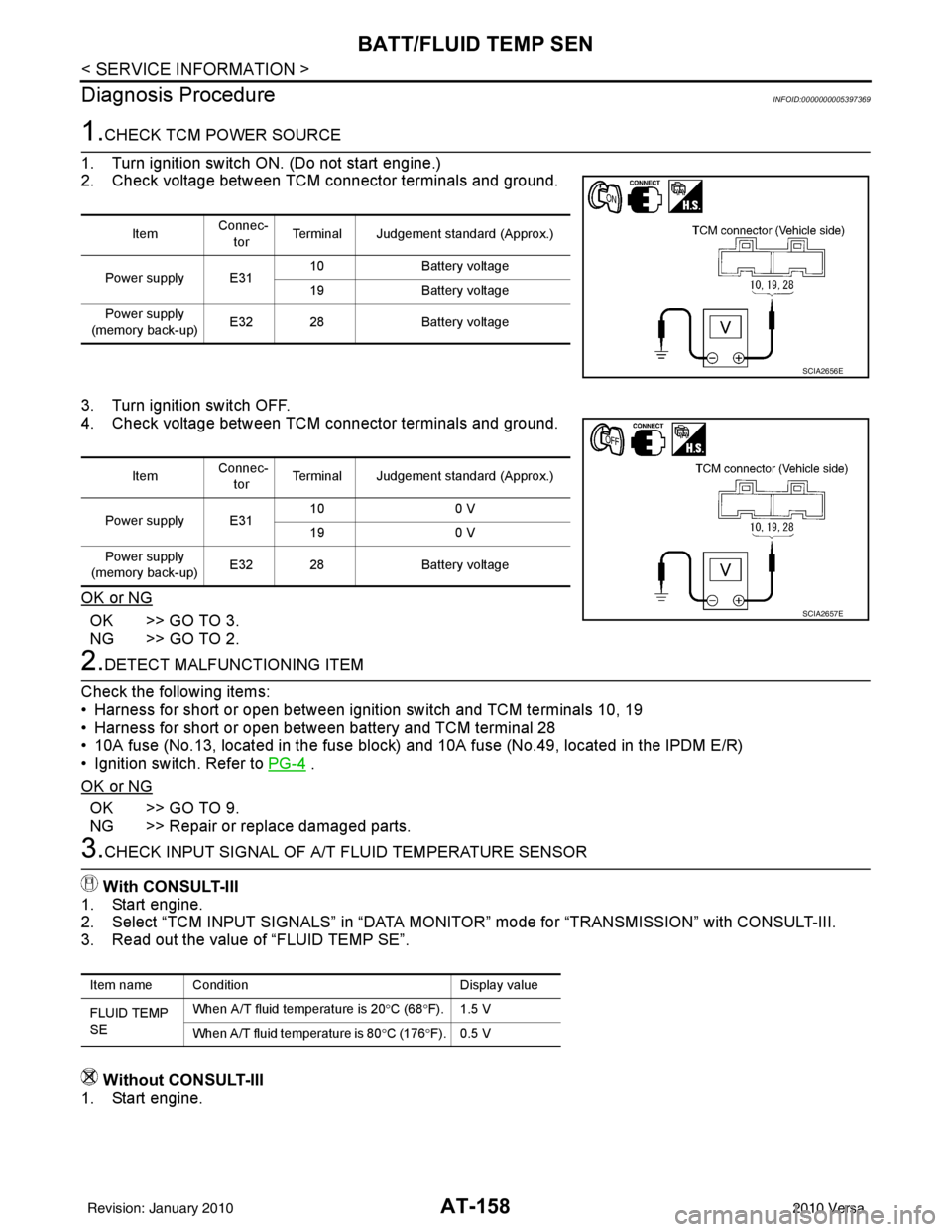
1. Turn ignition switch ON. (Do not start engine.)
2. Check voltage between TCM connector terminals and ground.
3. Turn ignition switch OFF.
4. Check voltage between TCM connector terminals and ground.
OK or NG
OK >> GO TO 3.
NG >> GO TO 2.
2.DETECT MALFUNCTIONING ITEM
Check the following items:
• Harness for short or open between ignition switch and TCM terminals 10, 19
• Harness for short or open between battery and TCM terminal 28
• 10A fuse (No.13, located in the fuse block) and 10A fuse (No.49, located in the IPDM E/R)
• Ignition switch. Refer to PG-4
.
OK or NG
OK >> GO TO 9.
NG >> Repair or replace damaged parts.
3.CHECK INPUT SIGNAL OF A/ T FLUID TEMPERATURE SENSOR
With CONSULT-III
1. Start engine.
2. Select “TCM INPUT SIGNALS” in “DATA MONITOR” mode for “TRANSMISSION” with CONSULT-III.
3. Read out the value of “FLUID TEMP SE”.
Without CONSULT-III
1. Start engine.
Item Connec-
tor Terminal Judgement standard (Approx.)
Power supply E31 10
Battery voltage
19 Battery voltage
Power supply
(memory back-up) E32 28
Battery voltage
SCIA2656E
Item Connec-
tor Terminal Judgement standard (Approx.)
Power supply E31 10
0 V
19 0 V
Power supply
(memory back-up) E32 28
Battery voltage
SCIA2657E
Item name Condition Display value
FLUID TEMP
SE When A/T fluid temperature is 20
°C (68 °F). 1.5 V
When A/T fluid temperature is 80 °C (176 °F). 0.5 V
Revision: January 20102010 Versa
Page 186 of 3745
MAIN POWER SUPPLY AND GROUND CIRCUITAT-169
< SERVICE INFORMATION >
DE
F
G H
I
J
K L
M A
B
AT
N
O P
Diagnosis ProcedureINFOID:0000000005397384
1.CHECK TCM POWER SOURCE
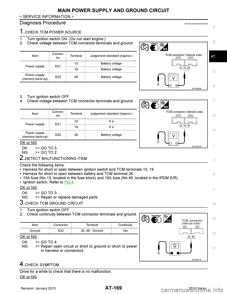
1. Turn ignition switch ON. (Do not start engine.)
2. Check voltage between TCM connector terminals and ground.
3. Turn ignition switch OFF.
4. Check voltage between TCM connector terminals and ground.
OK or NG
OK >> GO TO 3.
NG >> GO TO 2.
2.DETECT MALFUNCTIONING ITEM
Check the following items:
• Harness for short or open between ignition switch and TCM terminals 10, 19
• Harness for short or open between battery and TCM terminal 28
• 10A fuse (No.13, located in the fuse block) and 10A fuse (No.49, located in the IPDM E/R)
• Ignition switch. Refer to PG-4
.
OK or NG
OK >> GO TO 3.
NG >> Repair or replace damaged parts.
3.CHECK TCM GROUND CIRCUIT
1. Turn ignition switch OFF.
2. Check continuity between TCM connector terminals and ground.
OK or NG
OK >> GO TO 4.
NG >> Repair open circuit or short to ground or short to power in harness or connectors.
4.CHECK SYMPTOM
Drive for a while to check that there is no malfunction.
OK or NG
Item Connec-
tor Terminal Judgement standard (Approx.)
Power supply E31 10
Battery voltage
19 Battery voltage
Power supply
(memory back-up) E32 28
Battery voltage
SCIA2656E
ItemConnec-
tor Terminal Judgement standard (Approx.)
Power supply E31 10
0 V
19 0 V
Power supply
(memory back-up) E32 28
Battery voltage
SCIA2657E
Item Connector TerminalContinuity
Ground E3225, 48 - Ground Yes
SCIA2671E
Revision: January 20102010 Versa
Page 190 of 3745
TR SW, OD SW AND CLOSED THROTTLE, WIDE OPEN THROTTLE POSITION
SIGNAL CIRCUIT
AT-173
< SERVICE INFORMATION >
DE
F
G H
I
J
K L
M A
B
AT
N
O P
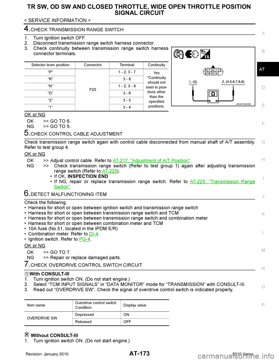
4.CHECK TRANSMISSION RANGE SWITCH
1. Turn ignition switch OFF.
2. Disconnect transmission range switch harness connector.
3. Check continuity between transmission range switch harness connector terminals.
OK or NG
OK >> GO TO 6.
NG >> GO TO 5.
5.CHECK CONTROL CABLE ADJUSTMENT
Check transmission range switch again with control cabl e disconnected from manual shaft of A/T assembly.
Refer to test group 4.
OK or NG
OK >> Adjust control cable. Refer to AT-217, "Adjustment of A/T Position".
NG >> Check transmission range switch (Refer to test group 1) again after adjusting transmission range switch (Refer to AT-225
).
• If OK, INSPECTION END
• If NG, repair or replace transmission range switch. Refer to AT-225, "
Transmission Range
Switch".
6.DETECT MALFUNCTIONING ITEM
Check the following.
• Harness for short or open between ignition switch and transmission range switch
• Harness for short or open between transmission range switch and TCM
• Harness for short or open between transmission range switch and combination meter
• Harness for short or open between combination meter and TCM
• 10A fuse (No.51, located in the IPDM E/R)
• Combination meter. Refer to DI-4
.
• Ignition switch. Refer to PG-4
.
OK or NG
OK >> GO TO 7.
NG >> Repair or replace damaged parts.
7.CHECK OVERDRIVE CO NTROL SWITCH CIRCUIT
With CONSULT-III
1. Turn ignition switch ON. (Do not start engine.)
2. Select “TCM INPUT SIGNALS” in “DATA MONI TOR” mode for “TRANSMISSION” with CONSULT-III.
3. Read out “OVERDRIVE SW”. Check the signal of ov erdrive control switch is indicated properly.
Without CONSULT-III
1. Turn ignition switch ON. (Do not start engine.)
Selector lever position Connector Terminal Continuity
“P”
F251 - 2, 3 - 7
Ye s
*Continuity should not
exist in posi-
tions other than the
specified
positions.
“R”
3 - 8
“N” 1 - 2, 3 - 9
“D” 3 - 6
“2” 3 - 5
“1” 3 - 4
JSDIA1503GB
Item nameOverdrive control switch
ConditionDisplay value
OVERDRIVE SW Depressed
ON
Released OFF
Revision: January 20102010 Versa
Page 198 of 3745
TROUBLE DIAGNOSIS FOR SYMPTOMSAT-181
< SERVICE INFORMATION >
DE
F
G H
I
J
K L
M A
B
AT
N
O P
OD OFF indicator lamp does not come on for abou t 2 seconds when turning ignition switch to ON.
DIAGNOSTIC PROCEDURE
1.CHECK CAN COMMUNICATION LINE
Perform self-diagnosis. Refer to AT-77, "
CONSULT-III Function (TRANSMISSION)" .
Is a malfunction in CAN communication indicated in the results?
YES >> Check CAN communication line. Refer to AT- 8 7 .
NO >> GO TO 2.
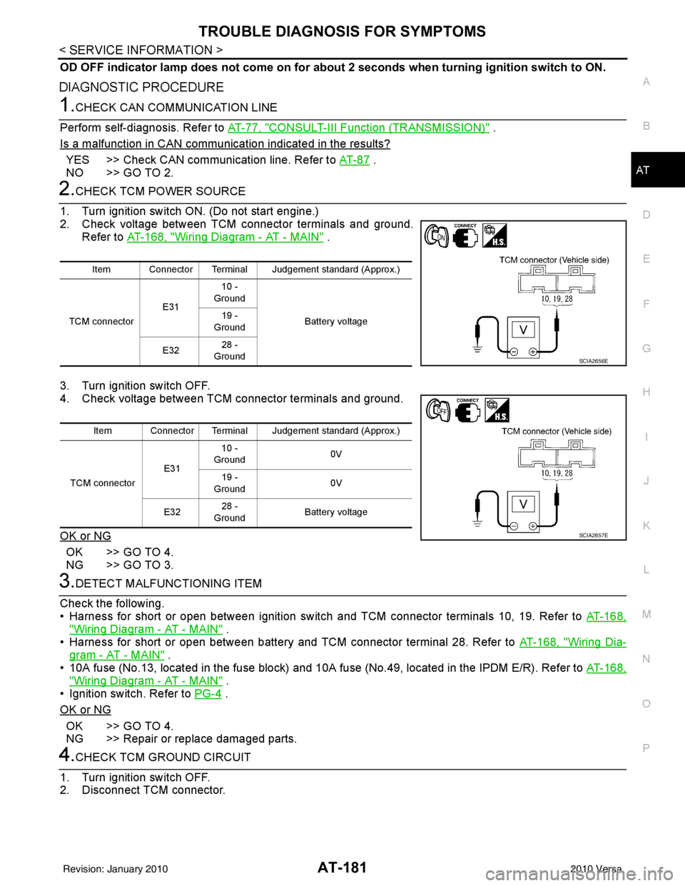
2.CHECK TCM POWER SOURCE
1. Turn ignition switch ON. (Do not start engine.)
2. Check voltage between TCM connector terminals and ground. Refer to AT-168, "
Wiring Diagram - AT - MAIN" .
3. Turn ignition switch OFF.
4. Check voltage between TCM connector terminals and ground.
OK or NG
OK >> GO TO 4.
NG >> GO TO 3.
3.DETECT MALFUNCTIONING ITEM
Check the following.
• Harness for short or open between ignition switch and TCM connector terminals 10, 19. Refer to AT-168,
"Wiring Diagram - AT - MAIN" .
• Harness for short or open between battery and TCM connector terminal 28. Refer to AT-168, "
Wiring Dia-
gram - AT - MAIN" .
• 10A fuse (No.13, located in the fuse block) and 10A fuse (No.49, located in the IPDM E/R). Refer to AT-168,
"Wiring Diagram - AT - MAIN" .
• Ignition switch. Refer to PG-4
.
OK or NG
OK >> GO TO 4.
NG >> Repair or replace damaged parts.
4.CHECK TCM GROUND CIRCUIT
1. Turn ignition switch OFF.
2. Disconnect TCM connector.
Item Connector Terminal Judgement standard (Approx.)
TCM connector E3110 -
Ground
Battery voltage
19 -
Ground
E32 28 -
Ground
SCIA2656E
Item Connector Terminal Judgement standard (Approx.)
TCM connector E3110 -
Ground 0V
19 -
Ground 0V
E32 28 -
Ground Battery voltage
SCIA2657E
Revision: January 20102010 Versa
Page 227 of 3745
AT-210
< SERVICE INFORMATION >
A/T SHIFT LOCK SYSTEM
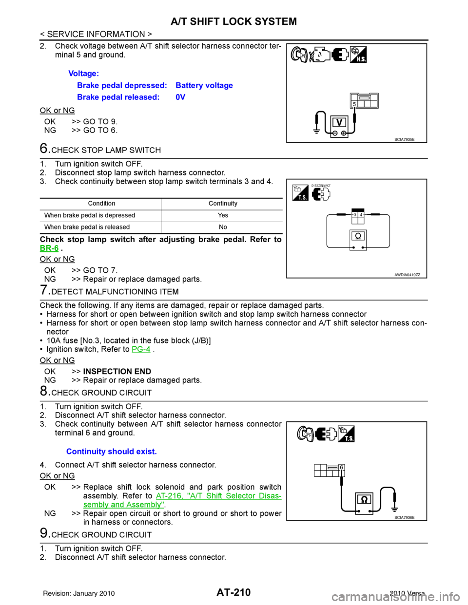
2. Check voltage between A/T shift selector harness connector ter-minal 5 and ground.
OK or NG
OK >> GO TO 9.
NG >> GO TO 6.
6.CHECK STOP LAMP SWITCH
1. Turn ignition switch OFF.
2. Disconnect stop lamp switch harness connector.
3. Check continuity between stop lamp switch terminals 3 and 4.
Check stop lamp switch after adjusting brake pedal. Refer to
BR-6
.
OK or NG
OK >> GO TO 7.
NG >> Repair or replace damaged parts.
7.DETECT MALFUNCTIONING ITEM
Check the following. If any items are damaged, repair or replace damaged parts.
• Harness for short or open between ignition switch and stop lamp switch harness connector
• Harness for short or open between stop lamp switch harness connector and A/T shift selector harness con-
nector
• 10A fuse [No.3, located in the fuse block (J/B)]
• Ignition switch, Refer to PG-4
.
OK or NG
OK >> INSPECTION END
NG >> Repair or replace damaged parts.
8.CHECK GROUND CIRCUIT
1. Turn ignition switch OFF.
2. Disconnect A/T shift selector harness connector.
3. Check continuity between A/T shift selector harness connector terminal 6 and ground.
4. Connect A/T shift selector harness connector.
OK or NG
OK >> Replace shift lock solenoid and park position switch assembly. Refer to AT-216, "
A/T Shift Selector Disas-
sembly and Assembly".
NG >> Repair open circuit or short to ground or short to power in harness or connectors.
9.CHECK GROUND CIRCUIT
1. Turn ignition switch OFF.
2. Disconnect A/T shift selector harness connector. Voltage:
Brake pedal depressed: Battery voltage
Brake pedal released: 0V
SCIA7935E
Condition Continuity
When brake pedal is depressed Yes
When brake pedal is released No
AWDIA0419ZZ
Continuity should exist.
SCIA7936E
Revision: January 20102010 Versa
Page 1149 of 3745
![NISSAN TIIDA 2010 Service Repair Manual CVT-116
< SERVICE INFORMATION >[RE0F08B]
P1701 TCM
• 10 A fuse (No.49, located in the IPDM E/R)
• 20 A fuse (No.53, located in the IPDM E/R)
• Ignition switch. Refer to
PG-4
.
OK or NG
OK >>](/img/5/57397/w960_57397-1148.png "NISSAN TIIDA 2010 Service Repair Manual CVT-116
< SERVICE INFORMATION >[RE0F08B]
P1701 TCM
• 10 A fuse (No.49, located in the IPDM E/R)
• 20 A fuse (No.53, located in the IPDM E/R)
• Ignition switch. Refer to
PG-4
.
OK or NG
OK >>")
CVT-116
< SERVICE INFORMATION >[RE0F08B]
P1701 TCM
• 10 A fuse (No.49, located in the IPDM E/R)
• 20 A fuse (No.53, located in the IPDM E/R)
• Ignition switch. Refer to
PG-4
.
OK or NG
OK >> GO TO 5.
NG >> Repair or replace damaged parts.
5.CHECK TCM GROUND CIRCUIT
1. Turn ignition switch OFF.
2. Disconnect TCM connector.
3. Check continuity between TCM connector terminals and ground.
OK or NG
OK >> GO TO 6.
NG >> Repair open circuit or short to ground or short to power in harness or connectors.
6.CHECK DTC
Perform CVT-113, "
DTC Confirmation Procedure" .
OK or NG
OK >> INSPECTION END
NG >> GO TO 7.
7.CHECK TCM
1. Check TCM input/output signals. Refer to CVT-46, "
TCM Terminal and Reference Value" .
2. If NG, re-check TCM pin terminals for damage or loose connection with harness connector.
OK or NG
OK >> INSPECTION END
NG >> Repair or replace damaged parts.
Name Connector Terminal Continuity
Ground E3225
Ye s
48
SCIA2671E
Revision: January 20102010 Versa
Page 1177 of 3745
![NISSAN TIIDA 2010 Service Repair Manual CVT-144
< SERVICE INFORMATION >[RE0F08B]
TROUBLE DIAGNOSIS FOR SYMPTOMS
O/D OFF indicator lamp does not
come on for about 2 seconds when turning ignition switch ON.
DIAGNOSTIC PROCEDURE
1.CHECK CAN](/img/5/57397/w960_57397-1176.png "NISSAN TIIDA 2010 Service Repair Manual CVT-144
< SERVICE INFORMATION >[RE0F08B]
TROUBLE DIAGNOSIS FOR SYMPTOMS
O/D OFF indicator lamp does not
come on for about 2 seconds when turning ignition switch ON.
DIAGNOSTIC PROCEDURE
1.CHECK CAN")
CVT-144
< SERVICE INFORMATION >[RE0F08B]
TROUBLE DIAGNOSIS FOR SYMPTOMS
O/D OFF indicator lamp does not
come on for about 2 seconds when turning ignition switch ON.
DIAGNOSTIC PROCEDURE
1.CHECK CAN COMMUNICATION LINE
Perform the self-diagnosis check. Refer to CVT-48, "
CONSULT-III Function (TRANSMISSION)".
Is any malfunction of the
“U1000” indicated in the results?
YES >> Check CAN communication line. Refer to CVT-56.
NO >> GO TO 2.
2.CHECK TCM POWER SOURCE
1. Turn ignition switch ON.
2. Check voltage between TCM connector terminals and ground. Refer to CVT-114, "
Wiring Diagram - CVT - POWER".
OK or NG
OK >> GO TO 4.
NG >> GO TO 3.
3.DETECT MALFUNCTIONING ITEM
Check the following.
• Harness for short or open between ignition switch and TCM connector terminal 10, 19 Refer to CVT-114, "
Wiring Diagram - CVT - POWER".
• 10 A fuse (No.49, located in the IPDM E/R). Refer to CVT-114, "
Wiring Diagram - CVT - POWER".
• Ignition switch. Refer to PG-4
.
OK or NG
OK >> GO TO 4.
NG >> Repair or replace damaged parts.
4.CHECK TCM GROUND CIRCUIT
1. Turn ignition switch OFF.
2. Disconnect TCM connector.
3. Check continuity between TCM connector terminals and ground. Refer to CVT-114, "
Wiring Diagram - CVT - POWER".
OK or NG
OK >> GO TO 5.
NG >> Repair open circuit or short to ground or short to power in harness or connectors.
5.DETECT MALFUNCTIONING ITEM
Check the following.
• Harness and fuse for short or open between ignition switch and O/D OFF indicator lamp Refer to PG-4
.
OK or NG
OK >> GO TO 6.
NG >> Repair or replace damaged parts.
6.CHECK SYMPTOM
Name Connec-
tor Terminal
Voltage (Approx.)
Power supply E31 10
Battery voltage
19 Battery voltage
SCIA4737E
NameConnec-
tor Terminal
Continuity
Ground E32 25
Ye s
48
SCIA2671E
Revision: January 20102010 Versa
Page 1190 of 3745
![NISSAN TIIDA 2010 Service Repair Manual CVT SHIFT LOCK SYSTEMCVT-157
< SERVICE INFORMATION > [RE0F08B]
D
E
F
G H
I
J
K L
M A
B
CVT
N
O P
2. Check voltage between CVT shift selector harness connector terminal 5 and ground.
OK or NG
OK >> GO](/img/5/57397/w960_57397-1189.png "NISSAN TIIDA 2010 Service Repair Manual CVT SHIFT LOCK SYSTEMCVT-157
< SERVICE INFORMATION > [RE0F08B]
D
E
F
G H
I
J
K L
M A
B
CVT
N
O P
2. Check voltage between CVT shift selector harness connector terminal 5 and ground.
OK or NG
OK >> GO")
CVT SHIFT LOCK SYSTEMCVT-157
< SERVICE INFORMATION > [RE0F08B]
D
E
F
G H
I
J
K L
M A
B
CVT
N
O P
2. Check voltage between CVT shift selector harness connector terminal 5 and ground.
OK or NG
OK >> GO TO 9.
NG >> GO TO 6.
6.CHECK STOP LAMP SWITCH
1. Turn ignition switch OFF.
2. Disconnect stop lamp switch harness connector.
3. Check continuity between stop lamp switch terminals 3 and 4.
Check stop lamp switch after adjusting brake pedal. Refer to
BR-6
.
OK or NG
OK >> GO TO 7.
NG >> Repair or replace damaged parts.
7.DETECT MALFUNCTIONING ITEM
Check the following. If any items are damaged, repair or replace damaged parts.
• Harness for short or open between ignition switch and stop lamp switch harness connector
• Harness for short or open between stop lamp switch harness connector and CVT shift selector harness con-
nector
• 10A fuse [No.3, located in the fuse block (J/B)]
• Ignition switch, Refer to PG-4
.
OK or NG
OK >> INSPECTION END
NG >> Repair or replace damaged parts.
8.CHECK GROUND CIRCUIT
1. Turn ignition switch OFF.
2. Disconnect CVT shift selector harness connector.
3. Check continuity between CVT shift selector harness connector terminal 6 and ground.
4. Connect CVT shift selector harness connector.
OK or NG
OK >> Replace shift lock solenoid and park position switch assembly. Refer to CVT-163, "
CVT Shift Selector Disas-
sembly and Assembly".
NG >> Repair open circuit or short to ground or short to power in harness or connectors.
9.CHECK GROUND CIRCUIT
1. Turn ignition switch OFF.
2. Disconnect CVT shift selector harness connector. Voltage:
Brake pedal depressed: Battery voltage
Brake pedal released: 0V
SCIA7935E
Condition Continuity
When brake pedal is depressed Yes
When brake pedal is released No
AWDIA0419ZZ
Continuity should exist.
SCIA7936E
Revision: January 20102010 Versa