Inspections before trouble diagnosis NISSAN TIIDA 2011 Service User Guide
[x] Cancel search | Manufacturer: NISSAN, Model Year: 2011, Model line: TIIDA, Model: NISSAN TIIDA 2011Pages: 3787, PDF Size: 78.35 MB
Page 207 of 3787
AT-190
< SERVICE INFORMATION >
TROUBLE DIAGNOSIS FOR SYMPTOMS
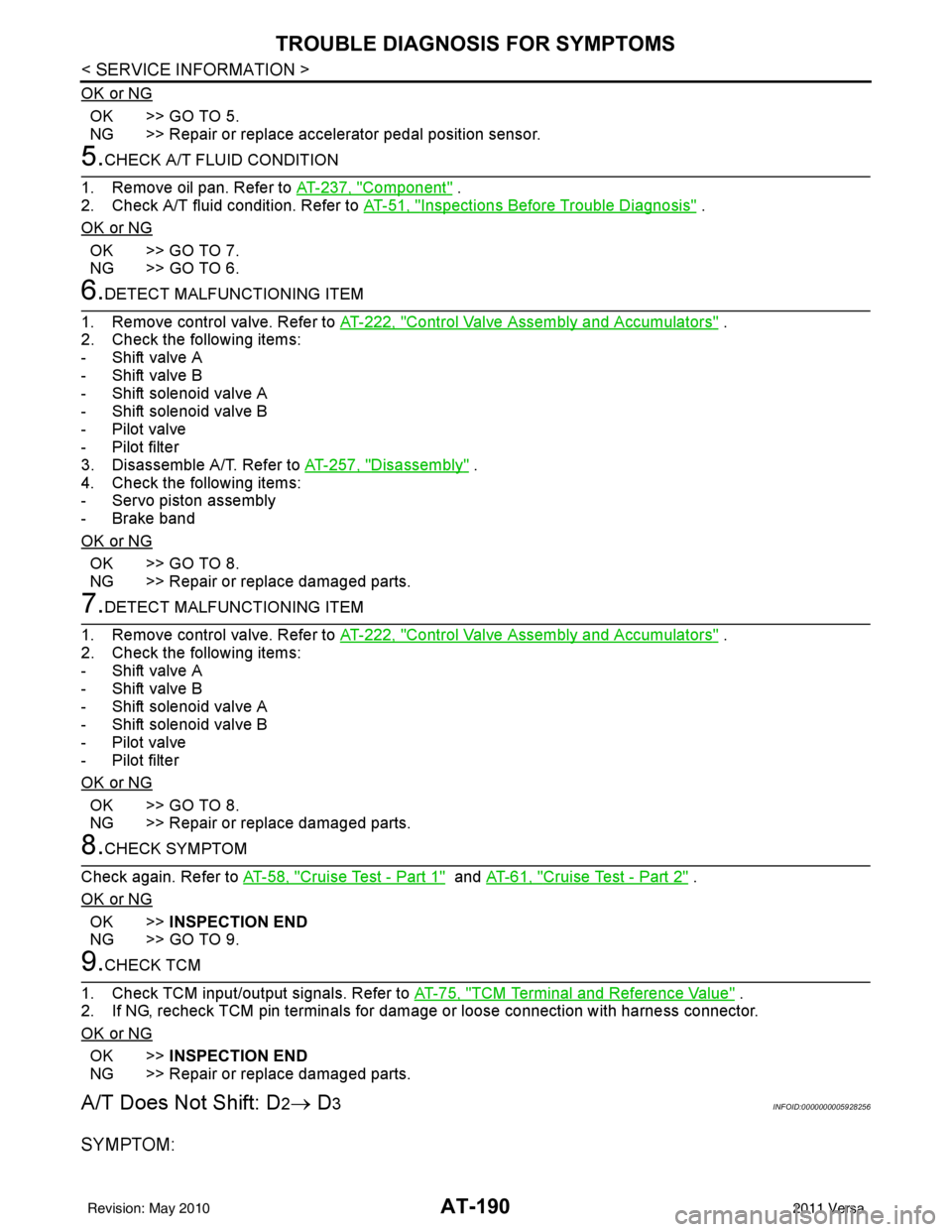
OK or NG
OK >> GO TO 5.
NG >> Repair or replace accelerator pedal position sensor.
5.CHECK A/T FLUID CONDITION
1. Remove oil pan. Refer to AT-237, "
Component" .
2. Check A/T fluid condition. Refer to AT-51, "
Inspections Before Trouble Diagnosis" .
OK or NG
OK >> GO TO 7.
NG >> GO TO 6.
6.DETECT MALFUNCTIONING ITEM
1. Remove control valve. Refer to AT-222, "
Control Valve Assembly and Accumulators" .
2. Check the following items:
- Shift valve A
- Shift valve B
- Shift solenoid valve A
- Shift solenoid valve B
- Pilot valve
- Pilot filter
3. Disassemble A/T. Refer to AT-257, "
Disassembly" .
4. Check the following items:
- Servo piston assembly
- Brake band
OK or NG
OK >> GO TO 8.
NG >> Repair or replace damaged parts.
7.DETECT MALFUNCTIONING ITEM
1. Remove control valve. Refer to AT-222, "
Control Valve Assembly and Accumulators" .
2. Check the following items:
- Shift valve A
- Shift valve B
- Shift solenoid valve A
- Shift solenoid valve B
- Pilot valve
- Pilot filter
OK or NG
OK >> GO TO 8.
NG >> Repair or replace damaged parts.
8.CHECK SYMPTOM
Check again. Refer to AT-58, "
Cruise Test - Part 1" and AT-61, "Cruise Test - Part 2" .
OK or NG
OK >> INSPECTION END
NG >> GO TO 9.
9.CHECK TCM
1. Check TCM input/output signals. Refer to AT-75, "
TCM Terminal and Reference Value" .
2. If NG, recheck TCM pin terminals for damage or loose connection with harness connector.
OK or NG
OK >> INSPECTION END
NG >> Repair or replace damaged parts.
A/T Does Not Shift: D2→ D3INFOID:0000000005928256
SYMPTOM:
Revision: May 2010 2011 Versa
Page 208 of 3787
TROUBLE DIAGNOSIS FOR SYMPTOMSAT-191
< SERVICE INFORMATION >
DE
F
G H
I
J
K L
M A
B
AT
N
O P
A/T does not shift from D2 to D3 at the specified speed on “Cruise Test — Part 1” and “Cruise Test —
Part 2”.
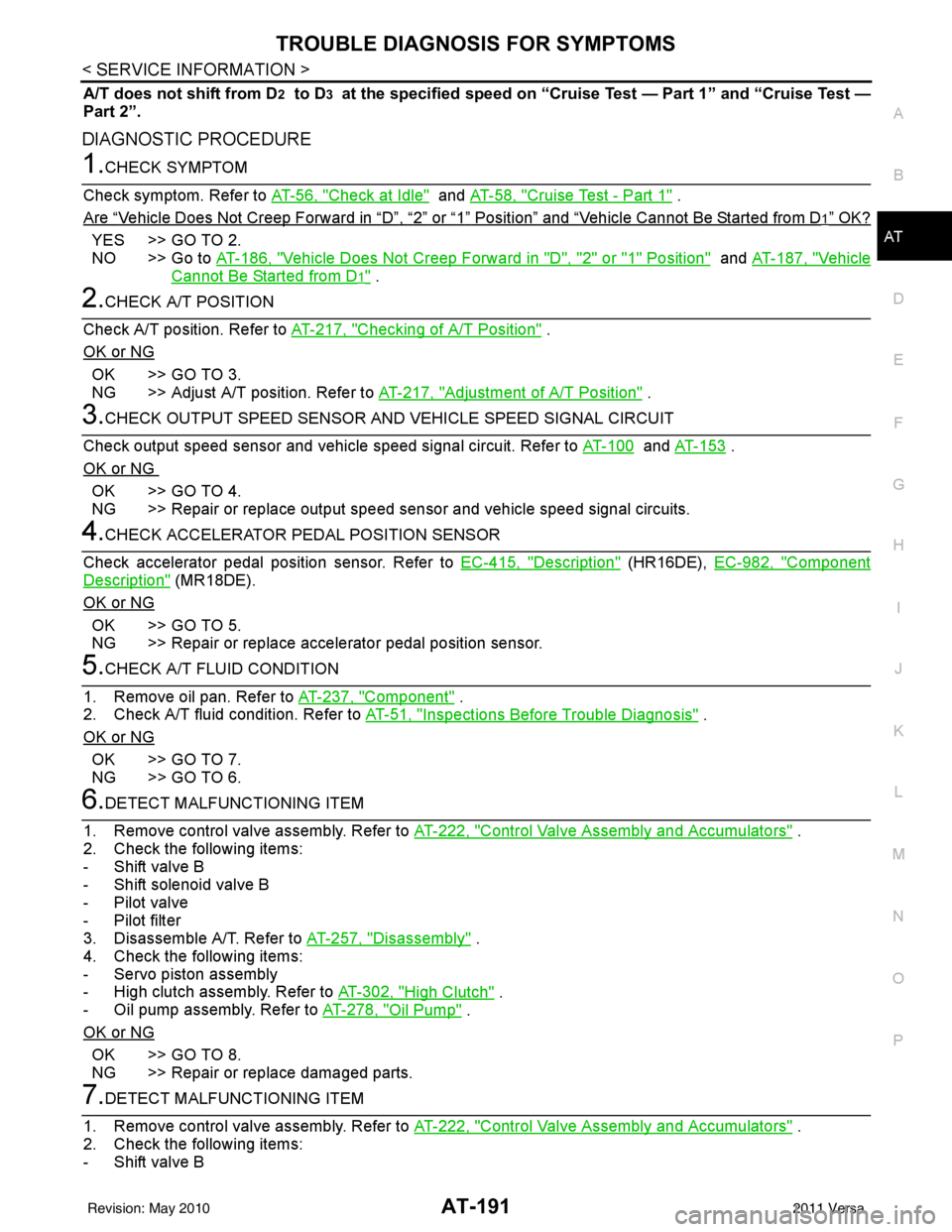
DIAGNOSTIC PROCEDURE
1.CHECK SYMPTOM
Check symptom. Refer to AT-56, "
Check at Idle" and AT-58, "Cruise Test - Part 1" .
Are
“Vehicle Does Not Creep Forward in “D”, “2” or “1” Position” and “Vehicle Cannot Be Started from D1” OK?
YES >> GO TO 2.
NO >> Go to AT-186, "
Vehicle Does Not Creep Forward in "D", "2" or "1" Position" and AT-187, "Vehicle
Cannot Be Started from D1" .
2.CHECK A/T POSITION
Check A/T position. Refer to AT-217, "
Checking of A/T Position" .
OK or NG
OK >> GO TO 3.
NG >> Adjust A/T position. Refer to AT-217, "
Adjustment of A/T Position" .
3.CHECK OUTPUT SPEED SENSOR AND VEHICLE SPEED SIGNAL CIRCUIT
Check output speed sensor and vehicle speed signal circuit. Refer to AT-100
and AT-153 .
OK or NG
OK >> GO TO 4.
NG >> Repair or replace output speed sensor and vehicle speed signal circuits.
4.CHECK ACCELERATOR PEDAL POSITION SENSOR
Check accelerator pedal position sensor. Refer to EC-415, "
Description" (HR16DE), EC-982, "Component
Description" (MR18DE).
OK or NG
OK >> GO TO 5.
NG >> Repair or replace accelerator pedal position sensor.
5.CHECK A/T FLUID CONDITION
1. Remove oil pan. Refer to AT-237, "
Component" .
2. Check A/T fluid condition. Refer to AT-51, "
Inspections Before Trouble Diagnosis" .
OK or NG
OK >> GO TO 7.
NG >> GO TO 6.
6.DETECT MALFUNCTIONING ITEM
1. Remove control valve assembly. Refer to AT-222, "
Control Valve Assembly and Accumulators" .
2. Check the following items:
- Shift valve B
- Shift solenoid valve B
- Pilot valve
- Pilot filter
3. Disassemble A/T. Refer to AT-257, "
Disassembly" .
4. Check the following items:
- Servo piston assembly
- High clutch assembly. Refer to AT-302, "
High Clutch" .
- Oil pump assembly. Refer to AT-278, "
Oil Pump" .
OK or NG
OK >> GO TO 8.
NG >> Repair or replace damaged parts.
7.DETECT MALFUNCTIONING ITEM
1. Remove control valve assembly. Refer to AT-222, "
Control Valve Assembly and Accumulators" .
2. Check the following items:
- Shift valve B
Revision: May 2010 2011 Versa
Page 209 of 3787
AT-192
< SERVICE INFORMATION >
TROUBLE DIAGNOSIS FOR SYMPTOMS
- Shift solenoid valve B
- Pilot valve
- Pilot filter
OK or NG
OK >> GO TO 8.
NG >> Repair or replace damaged parts.
8.CHECK SYMPTOM
Check again. Refer to AT-58, "
Cruise Test - Part 1" and AT-61, "Cruise Test - Part 2" .
OK or NG
OK >> INSPECTION END
NG >> GO TO 9.
9.CHECK TCM
1. Check TCM input/output signal. Refer to AT-75, "
TCM Terminal and Reference Value" .
2. If NG, recheck TCM pin terminals for damage or loose connection with harness connector.
OK or NG
OK >> INSPECTION END
NG >> Repair or replace damaged parts.
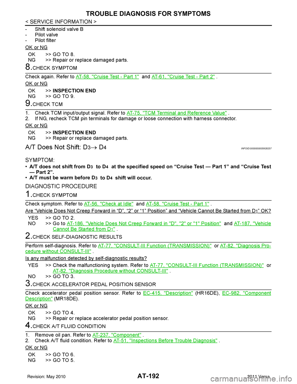
A/T Does Not Shift: D3→ D4INFOID:0000000005928257
SYMPTOM:
•A/T does not shift from D3 to D4 at the specified speed on “Cruise Test — Part 1” and “Cruise Test
— Part 2”.
• A/T must be warm before D
3 to D4 shift will occur.
DIAGNOSTIC PROCEDURE
1.CHECK SYMPTOM
Check symptom. Refer to AT-56, "
Check at Idle" and AT-58, "Cruise Test - Part 1" .
Are
“Vehicle Does Not Creep Forward in “D”, “2” or “1” Position” and “Vehicle Cannot Be Started from D1” OK?
YES >> GO TO 2.
NO >> Go to AT-186, "
Vehicle Does Not Creep Forward in "D", "2" or "1" Position" and AT-187, "Vehicle
Cannot Be Started from D1" .
2.CHECK SELF-DIAGNOSTIC RESULTS
Perform self-diagnosis. Refer to AT-77, "
CONSULT-III Function (TRANSMISSION)" or AT-82, "Diagnosis Pro-
cedure without CONSULT-III" .
Is any malfunction detected by self-diagnostic results?
YES >> Check the malfunctioning system. Refer to AT-77, "CONSULT-III Function (TRANSMISSION)" or
AT-82, "
Diagnosis Procedure without CONSULT-III" .
NO >> GO TO 3.
3.CHECK ACCELERATOR PEDAL POSITION SENSOR
Check accelerator pedal position sensor. Refer to EC-415, "
Description" (HR16DE), EC-982, "Component
Description" (MR18DE).
OK or NG
OK >> GO TO 4.
NG >> Repair or replace accelerator pedal position sensor.
4.CHECK A/T FLUID CONDITION
1. Remove oil pan. Refer to AT-237, "
Component" .
2. Check A/T fluid condition. Refer to AT-51, "
Inspections Before Trouble Diagnosis" .
OK or NG
OK >> GO TO 6.
NG >> GO TO 5.
Revision: May 2010 2011 Versa
Page 211 of 3787
AT-194
< SERVICE INFORMATION >
TROUBLE DIAGNOSIS FOR SYMPTOMS
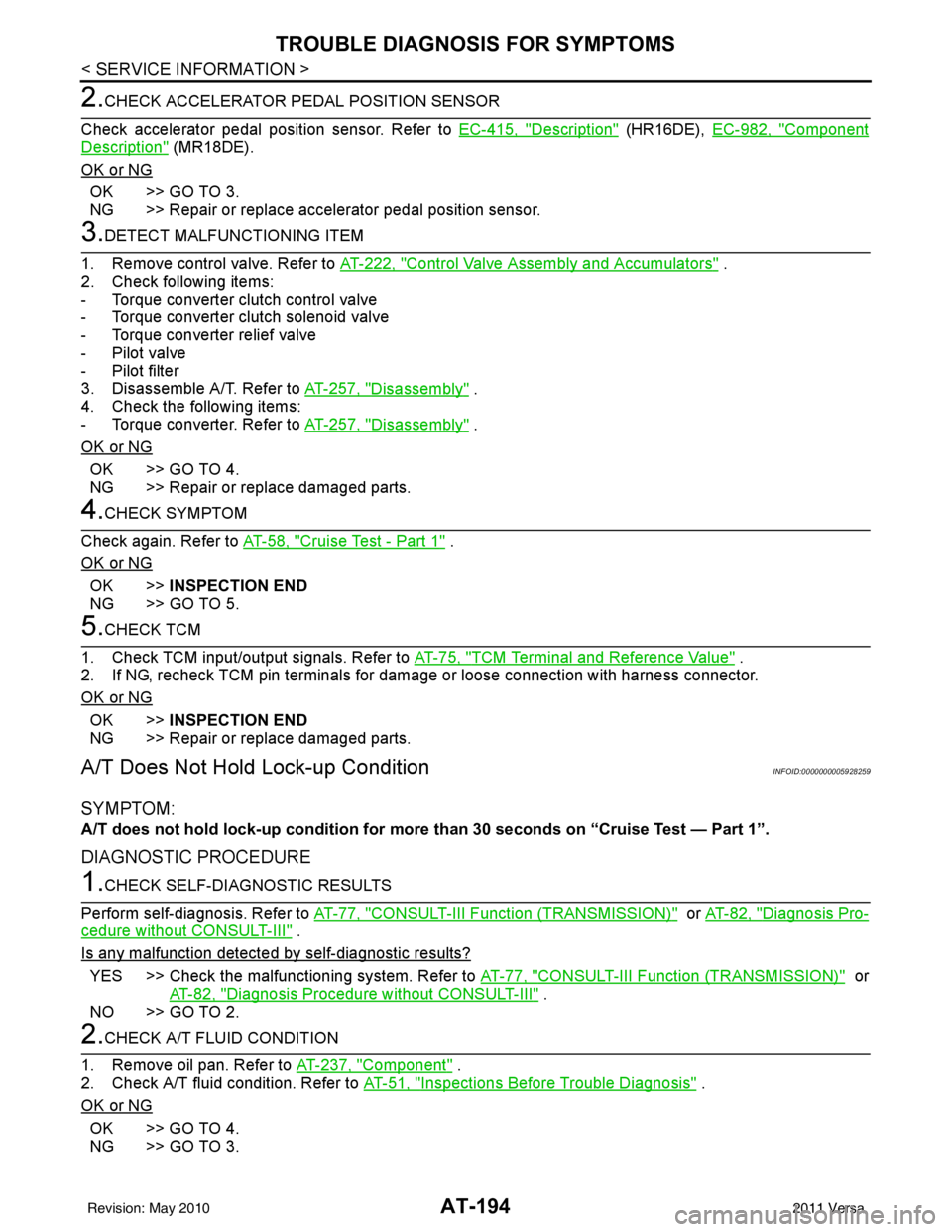
2.CHECK ACCELERATOR PEDAL POSITION SENSOR
Check accelerator pedal position sensor. Refer to EC-415, "
Description" (HR16DE), EC-982, "Component
Description" (MR18DE).
OK or NG
OK >> GO TO 3.
NG >> Repair or replace accelerator pedal position sensor.
3.DETECT MALFUNCTIONING ITEM
1. Remove control valve. Refer to AT-222, "
Control Valve Assembly and Accumulators" .
2. Check following items:
- Torque converter clutch control valve
- Torque converter clutch solenoid valve
- Torque converter relief valve
- Pilot valve
- Pilot filter
3. Disassemble A/T. Refer to AT-257, "
Disassembly" .
4. Check the following items:
- Torque converter. Refer to AT-257, "
Disassembly" .
OK or NG
OK >> GO TO 4.
NG >> Repair or replace damaged parts.
4.CHECK SYMPTOM
Check again. Refer to AT-58, "
Cruise Test - Part 1" .
OK or NG
OK >> INSPECTION END
NG >> GO TO 5.
5.CHECK TCM
1. Check TCM input/output signals. Refer to AT-75, "
TCM Terminal and Reference Value" .
2. If NG, recheck TCM pin terminals for damage or loose connection with harness connector.
OK or NG
OK >> INSPECTION END
NG >> Repair or replace damaged parts.
A/T Does Not Hold Lock-up ConditionINFOID:0000000005928259
SYMPTOM:
A/T does not hold lock-up condi tion for more than 30 seconds on “Cruise Test — Part 1”.
DIAGNOSTIC PROCEDURE
1.CHECK SELF-DIAGNOSTIC RESULTS
Perform self-diagnosis. Refer to AT-77, "
CONSULT-III Function (TRANSMISSION)" or AT-82, "Diagnosis Pro-
cedure without CONSULT-III" .
Is any malfunction detected by self-diagnostic results?
YES >> Check the malfunctioning system. Refer to AT-77, "CONSULT-III Function (TRANSMISSION)" or
AT-82, "
Diagnosis Procedure without CONSULT-III" .
NO >> GO TO 2.
2.CHECK A/T FLUID CONDITION
1. Remove oil pan. Refer to AT-237, "
Component" .
2. Check A/T fluid condition. Refer to AT-51, "
Inspections Before Trouble Diagnosis" .
OK or NG
OK >> GO TO 4.
NG >> GO TO 3.
Revision: May 2010 2011 Versa
Page 213 of 3787
AT-196
< SERVICE INFORMATION >
TROUBLE DIAGNOSIS FOR SYMPTOMS
OK >>INSPECTION END
NG >> GO TO 3.
3.CHECK TCM
1. Check TCM input/output signals. Refer to AT-75, "
TCM Terminal and Reference Value" .
2. If NG, recheck TCM pin terminals for damage or loose connection with harness connector.
OK or NG
OK >> INSPECTION END
NG >> Repair or replace damaged parts.
Engine Speed Does Not Return to Idle (Light Braking D4→ D3)INFOID:0000000005928261
SYMPTOM:
Engine speed does not smoothly return to idle when A/T shifts from D4 to D3 on “Cruise Test — Part
1”.
DIAGNOSTIC PROCEDURE
1.CHECK SELF-DIAGNOSTIC RESULTS
Perform self-diagnosis. Refer to AT-77, "
CONSULT-III Function (TRANSMISSION)" or AT-82, "Diagnosis Pro-
cedure without CONSULT-III" .
Is any malfunction detected by self-diagnostic results?
YES >> Check the malfunctioning system. Refer to AT-77, "CONSULT-III Function (TRANSMISSION)" or
AT-82, "
Diagnosis Procedure without CONSULT-III" .
NO >> GO TO 2.
2.CHECK ACCELERATOR PEDAL POSITION SENSOR
Check accelerator pedal position sensor. Refer to EC-415, "
Description" (HR16DE), EC-982, "Component
Description" (MR18DE).
OK or NG
OK >> GO TO 3.
NG >> Repair or replace accelerator pedal position sensor.
3.CHECK A/T FLUID CONDITION
1. Remove oil pan. Refer to AT-237, "
Component" .
2. Check A/T fluid condition. Refer to AT-51, "
Inspections Before Trouble Diagnosis" .
OK or NG
OK >> GO TO 5.
NG >> GO TO 4.
4.DETECT MALFUNCTIONING ITEM
1. Remove control valve assembly. Refer to AT-222, "
Control Valve Assembly and Accumulators" .
2. Check the following items:
- Overrun clutch control valve
- Overrun clutch reducing valve
- Overrun clutch solenoid valve
3. Disassemble A/T. Refer to AT-257, "
Disassembly" .
4. Check the following items:
- Overrun clutch assembly. Refer to AT-307, "
Forward and Overrun Clutches" .
OK or NG
OK >> GO TO 6.
NG >> Repair or replace damaged parts.
5.DETECT MALFUNCTIONING ITEM
1. Remove control valve assembly. Refer to AT-222, "
Control Valve Assembly and Accumulators" .
2. Check the following items:
- Overrun clutch control valve
- Overrun clutch reducing valve
- Overrun clutch solenoid valve
Revision: May 2010 2011 Versa
Page 217 of 3787
AT-200
< SERVICE INFORMATION >
TROUBLE DIAGNOSIS FOR SYMPTOMS
OK >> GO TO 3
NG >> Check transmission range switch. Refer to AT-175, "
Component Inspection" .
2.CHECK TRANSMISSION RANGE SWITCH CIRCUIT
Without CONSULT-III
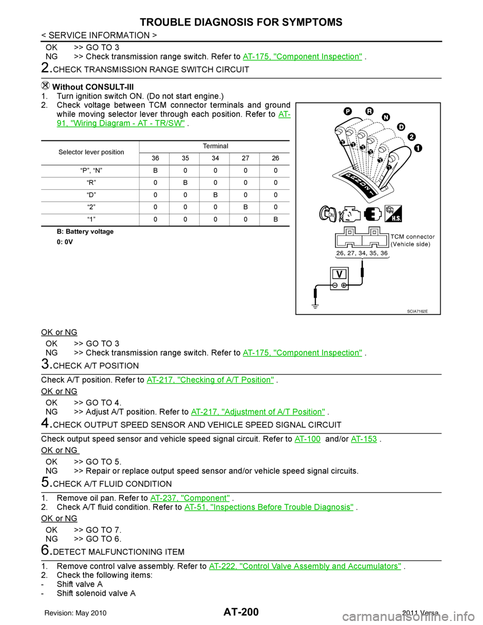
1. Turn ignition switch ON. (Do not start engine.)
2. Check voltage between TCM connector terminals and ground
while moving selector lever through each position. Refer to AT-
91, "Wiring Diagram - AT - TR/SW" .
B: Battery voltage
0: 0V
OK or NG
OK >> GO TO 3
NG >> Check transmission range switch. Refer to AT-175, "
Component Inspection" .
3.CHECK A/T POSITION
Check A/T position. Refer to AT-217, "
Checking of A/T Position" .
OK or NG
OK >> GO TO 4.
NG >> Adjust A/T position. Refer to AT-217, "
Adjustment of A/T Position" .
4.CHECK OUTPUT SPEED SENSOR AND VEHICLE SPEED SIGNAL CIRCUIT
Check output speed sensor and vehicle speed signal circuit. Refer to AT-100
and/or AT-153 .
OK or NG
OK >> GO TO 5.
NG >> Repair or replace output speed sens or and/or vehicle speed signal circuits.
5.CHECK A/T FLUID CONDITION
1. Remove oil pan. Refer to AT-237, "
Component" .
2. Check A/T fluid condition. Refer to AT-51, "
Inspections Before Trouble Diagnosis" .
OK or NG
OK >> GO TO 7.
NG >> GO TO 6.
6.DETECT MALFUNCTIONING ITEM
1. Remove control valve assembly. Refer to AT-222, "
Control Valve Assembly and Accumulators" .
2. Check the following items:
- Shift valve A
- Shift solenoid valve A
Selector lever position Te r m i n a l
36 35 34 27 26
“P”, “N” B0000 “R” 0B000
“D” 0 0 B 0 0
“2” 000B0
“1” 0000B
SCIA7162E
Revision: May 2010 2011 Versa
Page 220 of 3787
TROUBLE DIAGNOSIS FOR SYMPTOMSAT-203
< SERVICE INFORMATION >
DE
F
G H
I
J
K L
M A
B
AT
N
O P
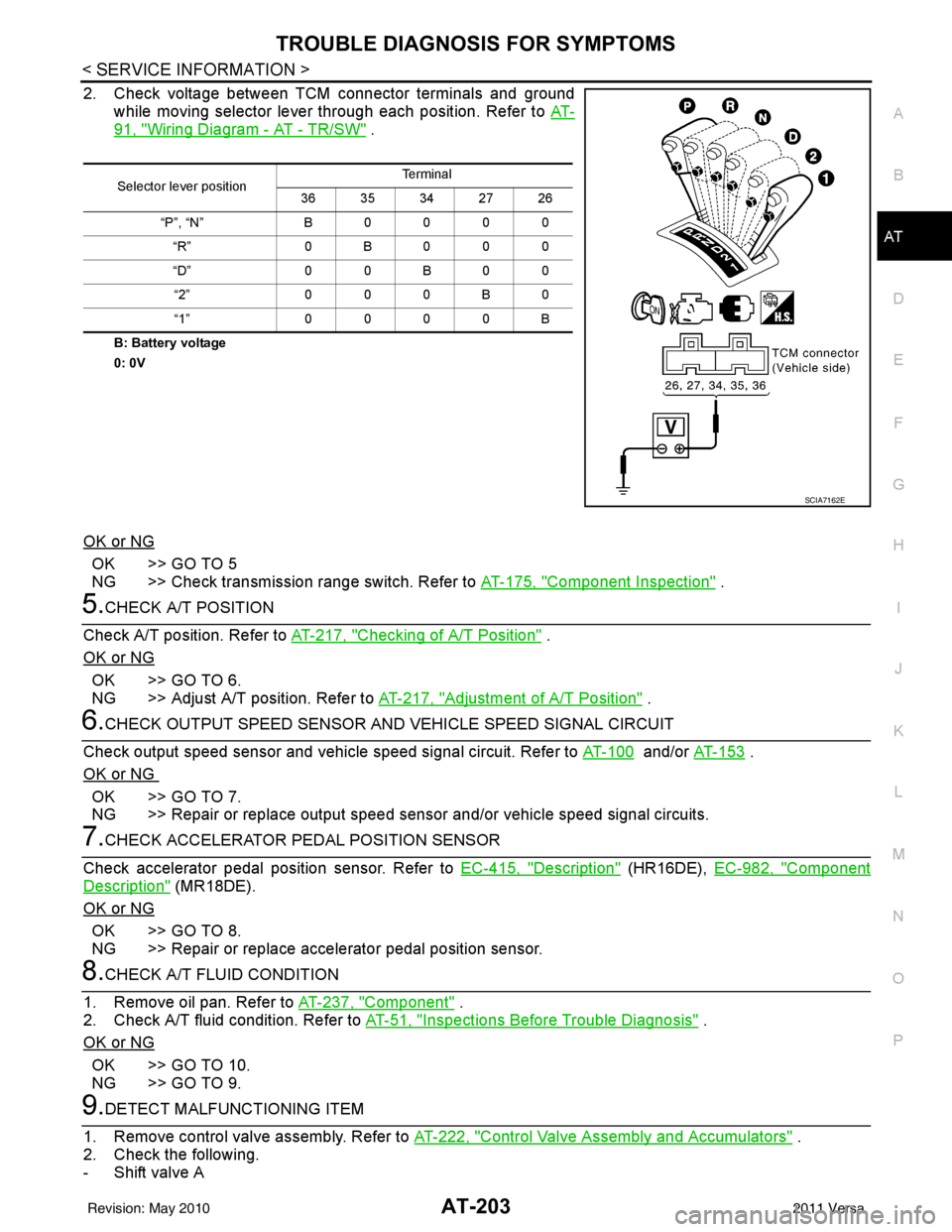
2. Check voltage between TCM connector terminals and ground while moving selector lever through each position. Refer to AT-
91, "Wiring Diagram - AT - TR/SW" .
B: Battery voltage
0: 0V
OK or NG
OK >> GO TO 5
NG >> Check transmission range switch. Refer to AT-175, "
Component Inspection" .
5.CHECK A/T POSITION
Check A/T position. Refer to AT-217, "
Checking of A/T Position" .
OK or NG
OK >> GO TO 6.
NG >> Adjust A/T position. Refer to AT-217, "
Adjustment of A/T Position" .
6.CHECK OUTPUT SPEED SENSOR AND VEHICLE SPEED SIGNAL CIRCUIT
Check output speed sensor and vehicle speed signal circuit. Refer to AT-100
and/or AT- 1 5 3 .
OK or NG
OK >> GO TO 7.
NG >> Repair or replace output speed sensor and/or vehicle speed signal circuits.
7.CHECK ACCELERATOR PEDAL POSITION SENSOR
Check accelerator pedal position sensor. Refer to EC-415, "
Description" (HR16DE), EC-982, "Component
Description" (MR18DE).
OK or NG
OK >> GO TO 8.
NG >> Repair or replace accelerator pedal position sensor.
8.CHECK A/T FLUID CONDITION
1. Remove oil pan. Refer to AT-237, "
Component" .
2. Check A/T fluid condition. Refer to AT-51, "
Inspections Before Trouble Diagnosis" .
OK or NG
OK >> GO TO 10.
NG >> GO TO 9.
9.DETECT MALFUNCTIONING ITEM
1. Remove control valve assembly. Refer to AT-222, "
Control Valve Assembly and Accumulators" .
2. Check the following.
- Shift valve A
Selector lever position Te r m i n a l
36 35 34 27 26
“P”, “N” B 0 0 0 0
“R” 0B000
“D” 0 0 B 0 0
“2” 0 0 0 B 0
“1” 0 0 0 0 B
SCIA7162E
Revision: May 2010 2011 Versa
Page 1056 of 3787

CVT-1
TRANSMISSION/TRANSAXLE
DE
F
G H
I
J
K L
M
SECTION CVT
A
B
CVT
N
O P
CONTENTS
CVT
RE0F08B
SERVICE INFORMATION .. ..........................
5
INDEX FOR DTC ............................................ .....5
Alphabetical Index ............................................... ......5
DTC No. Index ..........................................................5
PRECAUTIONS ...................................................7
Precaution for Supplemental Restraint System
(SRS) "AIR BAG" and "SEAT BELT PRE-TEN-
SIONER" ............................................................. ......
7
Precaution Necessary for Steering Wheel Rota-
tion After Battery Disconnect ............................... ......
7
Precaution for On Board Diagnosis (OBD) System
of CVT and Engine ....................................................
8
Service After Replacing TCM and Transaxle As-
sembly .......................................................................
8
Removal and Installation Procedure for CVT Unit
Connector ............................................................ ......
9
Precaution ...............................................................10
Service Notice or Precaution ...................................11
ATFTEMP COUNT Conversion Table ....................11
PREPARATION .............................................. ....13
Special Service Tool ........................................... ....13
Commercial Service Tool ........................................13
CVT FLUID .........................................................14
Checking CVT Fluid ............................................ ....14
Changing CVT Fluid ................................................15
CVT Fluid Cooler Cleaning .....................................15
CVT SYSTEM ................................................. ....19
Cross-Sectional View - RE0F08B ....................... ....19
Control System .................................................... ....20
Hydraulic Control System ........................................21
TCM Function ...................................................... ....21
CAN Communication ...............................................22
Input/Output Signal of TCM .....................................22
Line Pressure and Secondary Pressure Control .....23
Shift Control ............................................................23
Lock-up and Select Control .....................................25
Control Valve ....................................................... ....25
ON BOARD DIAGNOSTIC (OBD) SYSTEM ....27
Introduction ..............................................................27
OBD-II Function for CVT System ............................27
One or Two Trip Detection Logic of OBD-II .............27
OBD-II Diagnostic Trouble Code (DTC) ..................27
Malfunction Indicator Lamp (MIL) ............................28
TROUBLE DIAGNOSIS ....................................30
DTC Inspection Priority Chart ..................................30
Fail-Safe ..................................................................30
How to Perform Trouble Diagnosis for Quick and
Accurate Repair .......................................................
31
CVT Electrical Parts Location ..................................36
Circuit Diagram ........................................................37
Inspections before Trouble Diagnosis .....................37
Road Test ................................................................41
Check before Engine Is Started ...............................42
Check at Idle ............................................................42
Cruise Test ..............................................................43
Vehicle Speed When Shifting Gears .......................45
TCM Terminal and Reference Value .......................46
CONSULT-III Function (TRANSMISSION) .......... ....48
Diagnosis Procedure without CONSULT-III ............55
U1000 CAN COMM CIRCUIT ...........................56
Description ........................................................... ....56
On Board Diagnosis Logic .......................................56
Possible Cause ........................................................56
DTC Confirmation Procedure ..................................56
Wiring Diagram - CVT - CAN ...................................57
Diagnosis Procedure ...............................................58
U1010 CONTROL UNIT (CAN) .........................59
Description ...............................................................59
On Board Diagnosis Logic .......................................59
Possible Cause ........................................................59
DTC Confirmation Procedure ..................................59
Diagnosis Procedure ...............................................59
Revision: May 2010 2011 Versa
Page 1085 of 3787
![NISSAN TIIDA 2011 Service User Guide CVT-30
< SERVICE INFORMATION >[RE0F08B]
TROUBLE DIAGNOSIS
TROUBLE DIAGNOSIS
DTC Inspection Priority ChartINFOID:0000000005928748
If some DTCs are displayed at the same time, perform inspections one by NISSAN TIIDA 2011 Service User Guide CVT-30
< SERVICE INFORMATION >[RE0F08B]
TROUBLE DIAGNOSIS
TROUBLE DIAGNOSIS
DTC Inspection Priority ChartINFOID:0000000005928748
If some DTCs are displayed at the same time, perform inspections one by](/img/5/57396/w960_57396-1084.png)
CVT-30
< SERVICE INFORMATION >[RE0F08B]
TROUBLE DIAGNOSIS
TROUBLE DIAGNOSIS
DTC Inspection Priority ChartINFOID:0000000005928748
If some DTCs are displayed at the same time, perform inspections one by one based on the following priority
chart.
NOTE:
If DTC “U1000” is displayed with other DTCs, first perform the trouble diagnosis for DTC “U1000”.
Refer to
CVT-56
.
Fail-SafeINFOID:0000000005928749
The TCM has an electrical fail-safe mode. This mode make s it possible to operate even if there is an error in a
main electronic control input/output signal circuit.
FAIL-SAFE FUNCTION
If any malfunction occurs in a sensor or solenoid, this function controls the CVT to make driving possible.
Secondary Speed Sensor
The shift pattern is changed in accordance with thrott le position when an unexpected signal is sent from the
secondary speed sensor to the TCM. T he overdrive-off mode is inhibited, and the transaxle is put in “D”.
Primary Speed Sensor
The shift pattern is changed in accordance with thro ttle position and secondary speed (vehicle speed) when
an unexpected signal is sent from the primary speed sensor to the TCM. The overdrive-off mode is inhibited,
and the transaxle is put in “D”.
Transmission Range Switch
If an unexpected signal is sent from the transmission range switch to the TCM, the transaxle is put in “D”.
CVT Fluid Temperature Sensor
If an unexpected signal is sent from the CVT fluid temperature sensor to the TCM, the gear ratio in use before
receiving the unexpected signal is maintained or t he gear ratio is controlled to keep engine speed under 3500
rpm.
Secondary Pressure Sensor
• If an unexpected signal is sent from the secondary pressure sensor to the TCM, the secondary pressure
feedback control is stopped and the offset value obtai ned before the non-standard condition occurs is used
to control line pressure.
• If secondary pressure sensor error signal is input to TCM, secondary pressure feedback control stops, but line pressure is controlled normally.
Line Pressure Solenoid
If an unexpected signal is sent from the solenoid to the TCM, the line pressure solenoid is turned OFF to
achieve the maximum fluid pressure.
Secondary Pressure Solenoid
If an unexpected signal is sent from the solenoid to t he TCM, the secondary pressure solenoid is turned OFF
to achieve the maximum fluid pressure.
Torque Converter Clutch Solenoid
If an unexpected signal is sent from the solenoid to t he TCM, the torque converter clutch solenoid is turned
OFF to cancel the lock-up.
Step Motor
If an unexpected signal is sent from the step motor to the TCM, the step motor coil phases “A” through “D” are
all turned OFF to hold the gear ratio used right before the non-standard condition occurred.
CVT Lock-up Select Solenoid
If an unexpected signal is sent from the solenoid to the TCM, the CVT lock-up select solenoid is turned OFF to
cancel the lock-up.
Priority Detected items (DTC)
1 U1000
2 Except above
Revision: May 2010 2011 Versa
Page 1092 of 3787
![NISSAN TIIDA 2011 Service User Guide TROUBLE DIAGNOSISCVT-37
< SERVICE INFORMATION > [RE0F08B]
D
E
F
G H
I
J
K L
M A
B
CVT
N
O P
Circuit DiagramINFOID:0000000005928752
Inspections before Trouble DiagnosisINFOID:0000000005928753
CVT FLUID NISSAN TIIDA 2011 Service User Guide TROUBLE DIAGNOSISCVT-37
< SERVICE INFORMATION > [RE0F08B]
D
E
F
G H
I
J
K L
M A
B
CVT
N
O P
Circuit DiagramINFOID:0000000005928752
Inspections before Trouble DiagnosisINFOID:0000000005928753
CVT FLUID](/img/5/57396/w960_57396-1091.png)
TROUBLE DIAGNOSISCVT-37
< SERVICE INFORMATION > [RE0F08B]
D
E
F
G H
I
J
K L
M A
B
CVT
N
O P
Circuit DiagramINFOID:0000000005928752
Inspections before Trouble DiagnosisINFOID:0000000005928753
CVT FLUID CHECK
Fluid Leakage and Fluid Level Check
ABDWA0419GB
Revision: May 2010 2011 Versa