light NISSAN TIIDA 2011 Service Repair Manual
[x] Cancel search | Manufacturer: NISSAN, Model Year: 2011, Model line: TIIDA, Model: NISSAN TIIDA 2011Pages: 3787, PDF Size: 78.35 MB
Page 3090 of 3787
LT-58
< SERVICE INFORMATION >
TURN SIGNAL AND HAZARD WARNING LAMPS
3. Perform the preliminary check. Refer to LT-58, "Preliminary Check" .
4. Check symptom and repair or replace the cause of the malfunction.
5. Do turn signal and hazard warning lamps operate no rmally? If YES, GO TO 6. If NO, GO TO 4.
6. INSPECTION END
Preliminary CheckINFOID:0000000005929087
CHECK POWER SUPPLY AND GROUND CIRCUIT FOR BCM
Refer to BCS-16, "BCM Power Supply and Ground Circuit Inspection" .
CONSULT-III Function (BCM)INFOID:0000000005929088
Refer to BCS-17, "CONSULT-III Function (BCM)" .
Turn Signals Do Not OperateINFOID:0000000005929089
1.CHECK COMBINATION SWITCH (LIGHTING AND TURN SIGNAL SWITCH) INPUT SIGNAL
With CONSULT-III
1. Select “BCM” on CONSULT-III. Select “FLASHER” on “SELECT TEST ITEM” screen.
2. Select “DATA MONITOR” on “SELECT DIAG MODE ” screen. Make sure that “TURN SIGNAL R” and
“TURN SIGNAL L” turns ON-OFF linked with operation of lighting switch.
Without CONSULT-III
Refer to LT-65, "
Combination Switch Inspection" .
OK or NG
OK >> Replace the BCM. BCS-19, "Removal and Installation of BCM"
NG >> Check combination switch (lighting and turn signal switch). Refer to LT-65, "Combination Switch
Inspection" .
Front Turn Signal Lamp Does Not OperateINFOID:0000000005929090
1.CHECK BULB
Verify the bulb standard of each turn signal lamp is correct. Refer to LT-116, "
Exterior Lamp" .
OK or NG
OK >> GO TO 2.
NG >> Replace turn signal lamp bulb. Refer to LT-61, "
Bulb Replacement for Front Turn Signal Lamp" .
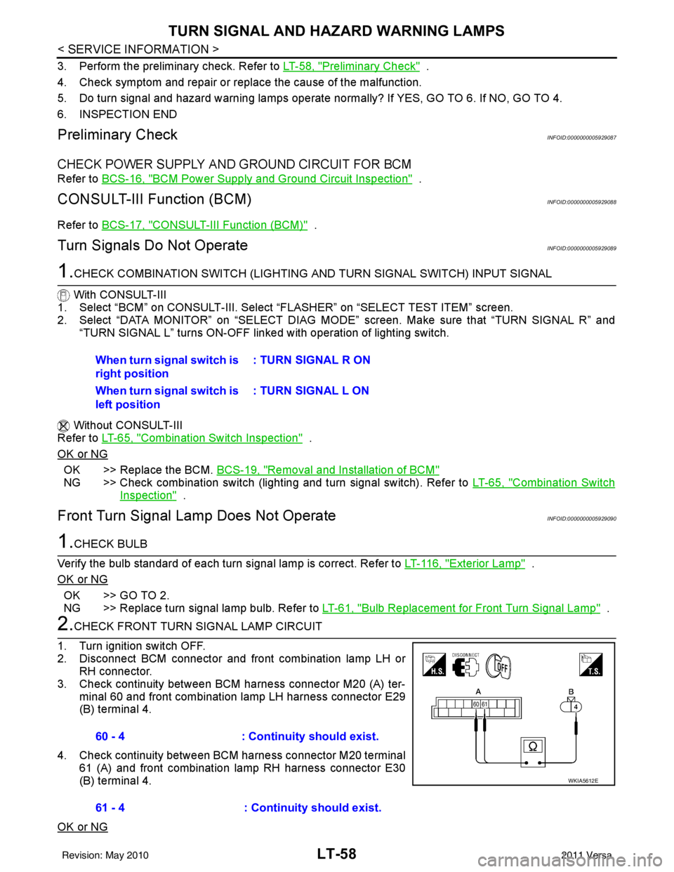
2.CHECK FRONT TURN SIGNAL LAMP CIRCUIT
1. Turn ignition switch OFF.
2. Disconnect BCM connector and front combination lamp LH or RH connector.
3. Check continuity between BCM harness connector M20 (A) ter- minal 60 and front combination lamp LH harness connector E29
(B) terminal 4.
4. Check continuity between BCM harness connector M20 terminal 61 (A) and front combination lamp RH harness connector E30
(B) terminal 4.
OK or NG
When turn signal switch is
right position : TURN SIGNAL R ON
When turn signal switch is
left position : TURN SIGNAL L ON
60 - 4
: Continuity should exist.
61 - 4 : Continuity should exist.
WKIA5612E
Revision: May 2010 2011 Versa
Page 3094 of 3787
LT-62
< SERVICE INFORMATION >
LIGHTING AND TURN SIGNAL SWITCH
LIGHTING AND TURN SIGNAL SWITCH
Removal and InstallationINFOID:0000000005929098
REMOVAL
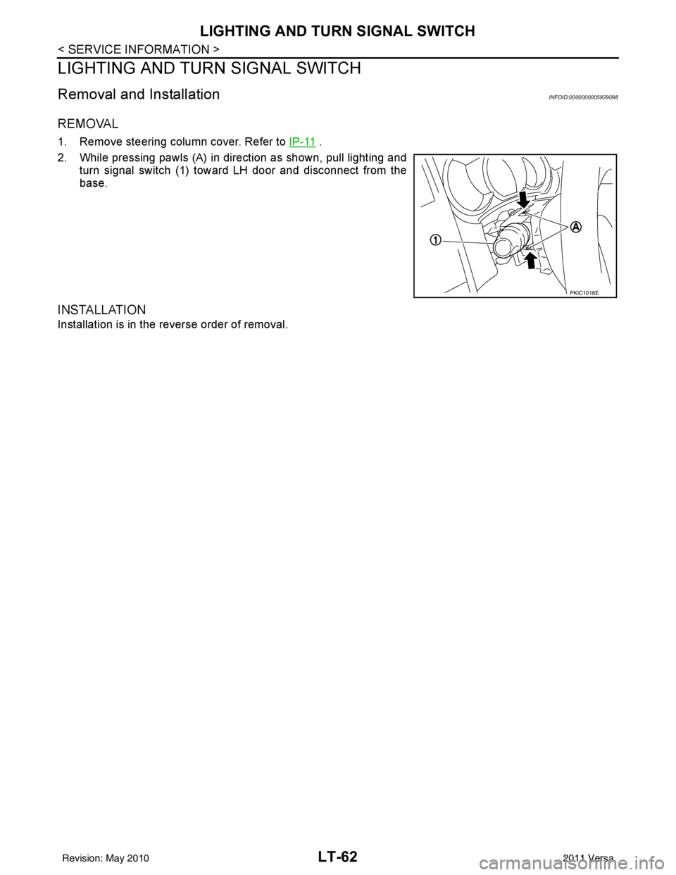
1. Remove steering column cover. Refer to IP-11 .
2. While pressing pawls (A) in direction as shown, pull lighting and turn signal switch (1) toward LH door and disconnect from the
base.
INSTALLATION
Installation is in the reverse order of removal.
PKIC1018E
Revision: May 2010 2011 Versa
Page 3097 of 3787
COMBINATION SWITCHLT-65
< SERVICE INFORMATION >
C
DE
F
G H
I
J
L
M A
B
LT
N
O P
Terminal and Reference Value for BCMINFOID:0000000005929102
Refer to BCS-12, "Terminal and Reference Value for BCM" .
CONSULT-III Function (BCM)INFOID:0000000005929103
Refer to BCS-17, "CONSULT-III Function (BCM)" .
Combination Switch InspectionINFOID:0000000005929104
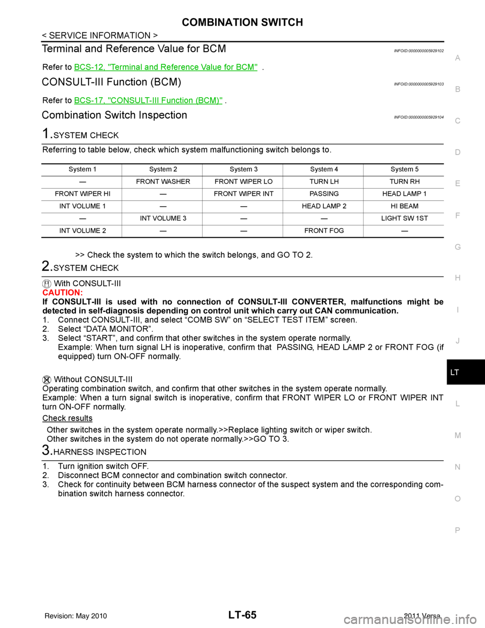
1.SYSTEM CHECK
Referring to table below, check which system malfunctioning switch belongs to.
>> Check the system to which the switch belongs, and GO TO 2.
2.SYSTEM CHECK
With CONSULT-III
CAUTION:
If CONSULT-III is used with no connection of CONSULT-III CONVERTER, malfunctions might be
detected in self-diagnosis de pending on control unit which carry out CAN communication.
1. Connect CONSULT-III, and select “C OMB SW” on “SELECT TEST ITEM” screen.
2. Select “DATA MONITOR”.
3. Select “START”, and confirm that other switches in the system operate normally.
Example: When turn signal LH is inoperative, confi rm that PASSING, HEAD LAMP 2 or FRONT FOG (if
equipped) turn ON-OFF normally.
Without CONSULT-III
Operating combination switch, and confirm that other switches in the system operate normally.
Example: When a turn signal switch is inoperative, confirm that FRONT WIPER LO or FRONT WIPER INT
turn ON-OFF normally.
Check results
Other switches in the system operate normall y.>>Replace lighting switch or wiper switch.
Other switches in the system do not operate normally.>>GO TO 3.
3.HARNESS INSPECTION
1. Turn ignition switch OFF.
2. Disconnect BCM connector and combination switch connector.
3. Check for continuity between BCM harness connecto r of the suspect system and the corresponding com-
bination switch harness connector.
System 1 System 2System 3System 4System 5
— FRONT WASHER FRONT WIPER LO TURN LHTURN RH
FRONT WIPER HI —FRONT WIPER INT PASSINGHEAD LAMP 1
INT VOLUME 1 ——HEAD LAMP 2 HI BEAM
— INT VOLUME 3 ——LIGHT SW 1ST
INT VOLUME 2 ——FRONT FOG —
Revision: May 2010 2011 Versa
Page 3098 of 3787
LT-66
< SERVICE INFORMATION >
COMBINATION SWITCH
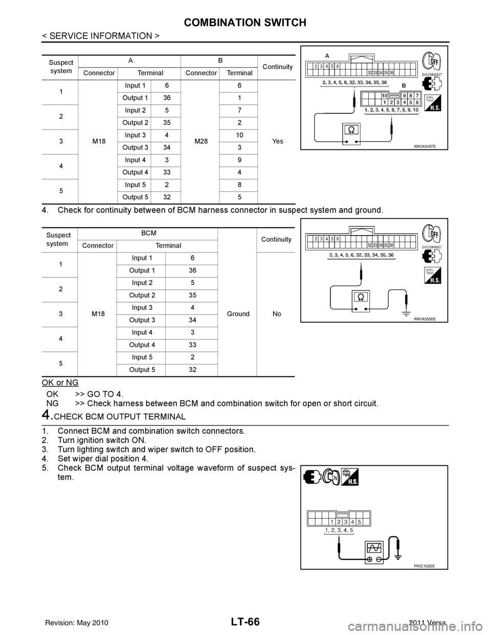
4. Check for continuity between of BCM harness connector in suspect system and ground.
OK or NG
OK >> GO TO 4.
NG >> Check harness between BCM and combination switch for open or short circuit.
4.CHECK BCM OUTPUT TERMINAL
1. Connect BCM and combination switch connectors.
2. Turn ignition switch ON.
3. Turn lighting switch and wiper switch to OFF position.
4. Set wiper dial position 4.
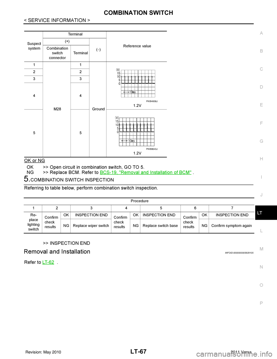
5. Check BCM output terminal voltage waveform of suspect sys- tem.
Suspect
system AB
Continuity
Connector Terminal Connector Terminal
1
M18Input 1 6
M286
Ye s
Output 1 36
1
2 Input 2 5
7
Output 2 35 2
3 Input 3 4
10
Output 3 34 3
4 Input 4 3
9
Output 4 33 4
5 Input 5 2
8
Output 5 32 5
Suspect
system BCM
Continuity
Connector Terminal
1
M18 Input 1
6
Ground No
Output 1 36
2 Input 2
5
Output 2 35
3 Input 3
4
Output 3 34
4 Input 4
3
Output 4 33
5 Input 5
2
Output 5 32
WKIA5497E
WKIA5500E
PKIC1020E
Revision: May 2010 2011 Versa
Page 3099 of 3787
COMBINATION SWITCHLT-67
< SERVICE INFORMATION >
C
DE
F
G H
I
J
L
M A
B
LT
N
O P
OK or NG
OK >> Open circuit in combination switch, GO TO 5.
NG >> Replace BCM. Refer to BCS-19, "
Removal and Installation of BCM" .
5.COMBINATION SWITCH INSPECTION
Referring to table below, perform combination switch inspection.
>> INSPECTION END
Removal and InstallationINFOID:0000000005929105
Refer to LT- 6 2 .
Suspect
system Te r m i n a l
Reference value
(+)
(−)
Combination
switch
connector Te r m i n a l
1
M28 1
Ground 1.2V
22
33
44
55
1.2V
PKIB4958J
PKIB8643J
Procedure
12 3 4 5 6 7
Re-
place
lighting switch Confirm
check
results
OK INSPECTION END
Confirm
check
resultsOK INSPECTION END
Confirm
check
resultsOK INSPECTION END
NG Replace wiper switch NG Replace switch baseNG Confirm symptom again
Revision: May 2010 2011 Versa
Page 3106 of 3787
LT-74
< SERVICE INFORMATION >
PARKING, LICENSE PLATE AND TAIL LAMPS
PARKING, LICENSE PLATE AND TAIL LAMPS
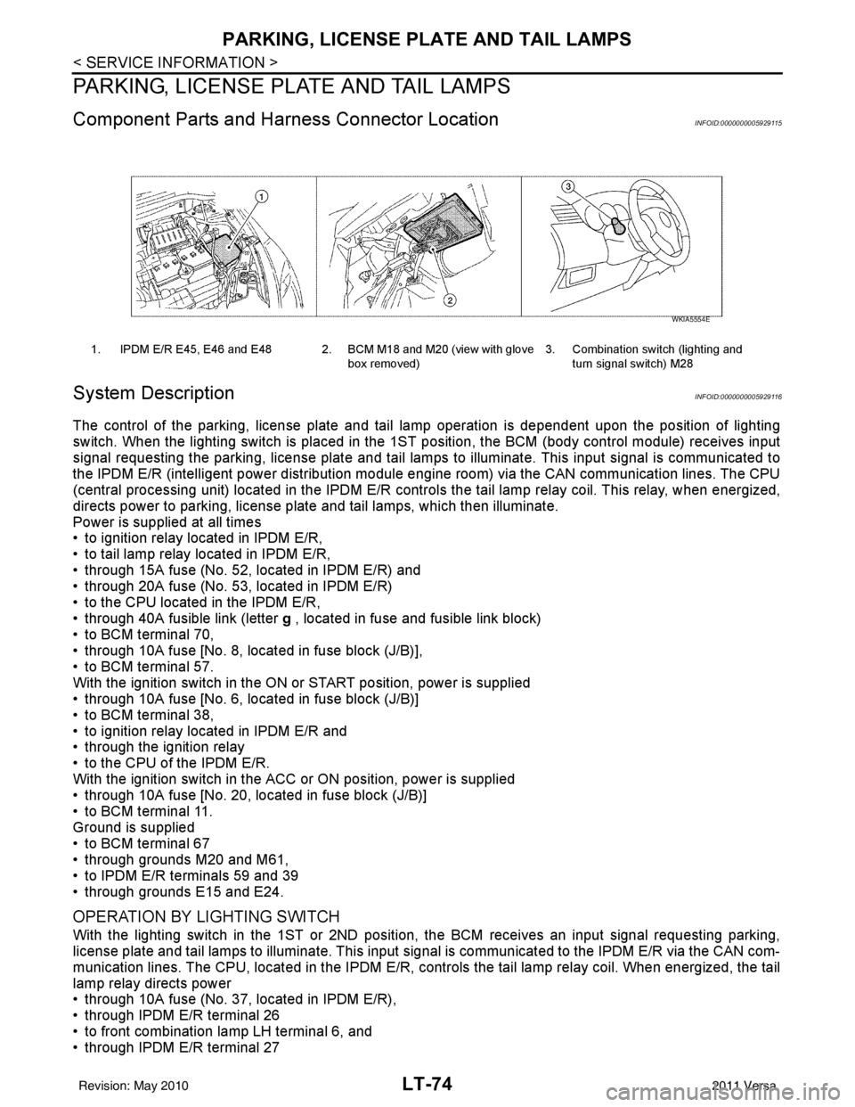
Component Parts and Harness Connector LocationINFOID:0000000005929115
System DescriptionINFOID:0000000005929116
The control of the parking, license plate and tail lamp operation is dependent upon the position of lighting
switch. When the lighting switch is placed in the 1ST position, the BCM (body cont rol module) receives input
signal requesting the parking, license plate and tail lamps to illuminate. This input signal is communicated to
the IPDM E/R (intelligent power distribution module engine room) via the CAN communication lines. The CPU
(central processing unit) located in the IPDM E/R contro ls the tail lamp relay coil. This relay, when energized,
directs power to parking, license plate and tail lamps, which then illuminate.
Power is supplied at all times
• to ignition relay located in IPDM E/R,
• to tail lamp relay located in IPDM E/R,
• through 15A fuse (No. 52, located in IPDM E/R) and
• through 20A fuse (No. 53, located in IPDM E/R)
• to the CPU located in the IPDM E/R,
• through 40A fusible link (letter g , located in fuse and fusible link block)
• to BCM terminal 70,
• through 10A fuse [No. 8, located in fuse block (J/B)],
• to BCM terminal 57.
With the ignition switch in the ON or START position, power is supplied
• through 10A fuse [No. 6, located in fuse block (J/B)]
• to BCM terminal 38,
• to ignition relay located in IPDM E/R and
• through the ignition relay
• to the CPU of the IPDM E/R.
With the ignition switch in the ACC or ON position, power is supplied
• through 10A fuse [No. 20, located in fuse block (J/B)]
• to BCM terminal 11.
Ground is supplied
• to BCM terminal 67
• through grounds M20 and M61,
• to IPDM E/R terminals 59 and 39
• through grounds E15 and E24.
OPERATION BY LIGHTING SWITCH
With the lighting switch in the 1ST or 2ND position, the BCM receives an input signal requesting parking,
license plate and tail lamps to illuminate. This input signal is communicated to the IPDM E/R via the CAN com-
munication lines. The CPU, located in the IPDM E/R, controls the tail lamp relay coil. When energized, the tail
lamp relay directs power
• through 10A fuse (No. 37, located in IPDM E/R),
• through IPDM E/R terminal 26
• to front combination lamp LH terminal 6, and
• through IPDM E/R terminal 27
1. IPDM E/R E45, E46 and E48 2. BCM M18 and M20 (view with glove
box removed)3. Combination switch (lighting and
turn signal switch) M28
WKIA5554E
Revision: May 2010 2011 Versa
Page 3107 of 3787
PARKING, LICENSE PLATE AND TAIL LAMPS
LT-75
< SERVICE INFORMATION >
C
D E
F
G H
I
J
L
M A
B
LT
N
O P
• to front combination lamp RH terminal 6,
• through IPDM E/R terminal 28
• to rear combination lamp LH terminal 4 and
• to license plate lamp LH and RH terminal 1,
• through IPDM E/R terminal 29
• to rear combination lamp RH terminal 4.
Ground is supplied
• to front combination lamp LH and RH terminal 7
• through grounds E15 and E24,
• to rear combination lamp LH terminal 1 and
• to license plate lamp LH and RH terminal 2
• through grounds B7 and B19, and
• to rear combination lamp RH terminal 1
• through grounds B117, B132 (all models) and D402 (with hatchback).
With power and ground supplied, parking, license plate and tail lamps illuminate.
COMBINATION SWITCH READING FUNCTION
Refer to BCS-4, "System Description" .
EXTERIOR LAMP BATTERY SAVER CONTROL
When the combination switch (lighting and turn signal switch) is in the 1ST (or 2ND) position and the ignition
switch is turned from ON or ACC to OFF, t he battery saver control feature is activated.
Under this condition, the parking, license and tail lamps remain illumi nated for 5 minutes, then the parking,
license plate and tail lamps are turned off.
Exterior lamp battery saver control mode can be changed by the function setting of CONSULT-III.
CAN Communication System DescriptionINFOID:0000000005929117
Refer to LAN-7, "System Description" .
Revision: May 2010 2011 Versa
Page 3113 of 3787
PARKING, LICENSE PLATE AND TAIL LAMPS
LT-81
< SERVICE INFORMATION >
C
D E
F
G H
I
J
L
M A
B
LT
N
O P
How to Proceed with Trouble DiagnosisINFOID:0000000005929122
1. Confirm the symptom or customer complaint.
2. Understand operation description and function description. Refer to LT-74, "
System Description" .
3. Perform the preliminary check. Refer to LT-81, "
Preliminary Check" .
4. Check symptom and repair or replace the cause of the malfunction.
5. Do the parking, license plate and tail lamps operate normally? If YES, GO TO 6. If NO, GO TO 4.
6. Inspection End.
Preliminary CheckINFOID:0000000005929123
CHECK POWER SUPPLY AND GROUND CIRCUIT FOR BCM
Refer to BCS-16, "BCM Power Supply and Ground Circuit Inspection" .
CHECK POWER SUPPLY AND GROUND CIRCUIT FOR IPDM E/R
Refer to PG-27, "IPDM E/R Power/Ground Circuit Inspection" .
CONSULT-III Function (BCM)INFOID:0000000005929124
Refer to BCS-17, "CONSULT-III Function (BCM)" .
CONSULT-III Function (IPDM E/R)INFOID:0000000005929125
Refer to PG-18, "CONSULT-III Function (IPDM E/R)" .
Parking, License Plate and Tail Lamps Do Not IlluminateINFOID:0000000005929126
1.CHECK TAIL LAMP FUSE
Inspect tail lamp 10A fuse (No. 37, located in IPDM E/R).
OK or NG
OK >> GO TO 2.
NG >> Repair harness.
2.CHECK COMBINATION SWITCH (LIGHTING AND TURN SIGNAL SWITCH) INPUT SIGNAL
With CONSULT-III
1. Select “BCM” on CONSULT-III. Select “HEAD LAMP” on “SELECT TEST ITEM” screen.
2. Select “DATA MONITOR” on “SELECT DIAG MODE” screen. Make sure “LIGHT SW 1ST” turns ON-OFF linked with operation of lighting switch.
Without CONSULT-III
Refer to LT-65, "
Combination Switch Inspection" .
OK or NG
OK >> GO TO 3.
NG >> Check combination switch (lighting and turn signal switch). Refer to LT-65, "
Combination Switch
Inspection" .
3.ACTIVE TEST
With CONSULT-III
1. Select “IPDM E/R” on CONSUL T-III, and select “ACTIVE TEST” on “SELECT DIAG MODE” screen.
2. Select “EXTERNAL LAMPS” on “SELECT TEST ITEM” screen.
3. Touch “TAIL” on "ACTIVE TEST" screen.
4. Make sure parking, license plate and tail lamps operate. When lighting switch is 1ST
position
: LIGHT SW 1ST ON
Parking, license plate and tail lamps should oper-
ate.
Revision: May 2010
2011 Versa
Page 3114 of 3787
LT-82
< SERVICE INFORMATION >
PARKING, LICENSE PLATE AND TAIL LAMPS
Without CONSULT-III
1. Start auto active test. Refer to PG-20, "
Auto Active Test" .
2. Make sure parking, license plate and tail lamps operate.
OK or NG
OK >> GO TO 4.
NG >> GO TO 5.
4.CHECK IPDM E/R
1. Select “IPDM E/R” on CONSULT-III, and select “DATA MONITOR” on “SELECT DIAG MODE” screen.
2. Make sure “TAIL&CLR REQ” turns ON when lighting switch is in 1ST position.
OK or NG
OK >> Replace IPDM E/R. Refer to PG-28, "Removal and Installation of IPDM E/R" .
NG >> Replace BCM. Refer to BCS-19, "
Removal and Installation of BCM" .
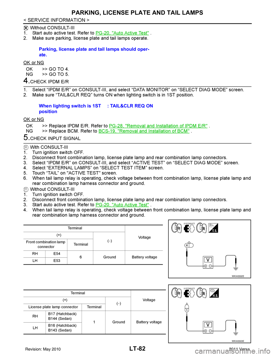
5.CHECK INPUT SIGNAL
With CONSULT-III
1. Turn ignition switch OFF.
2. Disconnect front combination lamp, license plate lamp and rear combination lamp connectors.
3. Select “IPDM E/R” on CONSULT-III, and sele ct “ACTIVE TEST” on “SELECT DIAG MODE” screen.
4. Select “EXTERNAL LAMPS” on “SELECT TEST ITEM” screen.
5. Touch “TAIL” on "ACTIVE TEST" screen.
6. When tail lamp relay is operating, check voltage between front combination lamp, license plate lamp and rear combination lamp harness connector and ground.
Without CONSULT-III
1. Turn ignition switch OFF.
2. Disconnect front combination lamp, license plate lamp and rear combination lamp connectors.
3. Start auto active test. Refer to PG-20, "
Auto Active Test" .
4. When tail lamp relay is operating, check voltage between front combination lamp, license plate lamp and rear combination lamp harness connector and ground.Parking, license plate and tail lamps should oper-
ate.
When lighting switch is 1ST
position
: TAIL&CLR REQ ON
Te r m i n a l
Voltag e
(+)
(−)
Front combination lamp
connector Te r m i n a l
RH E54 6Ground Battery voltage
LH E53
WKIA5502E
Te r m i n a l
Vo l ta g e
(+)
(−)
License plate lamp connector Terminal
RH B17 (Hatchback)
B144 (Sedan)
1 Ground Battery voltage
LH B16 (Hatchback)
B143 (Sedan)
WKIA5503E
Revision: May 2010
2011 Versa
Page 3116 of 3787
LT-84
< SERVICE INFORMATION >
PARKING, LICENSE PLATE AND TAIL LAMPS
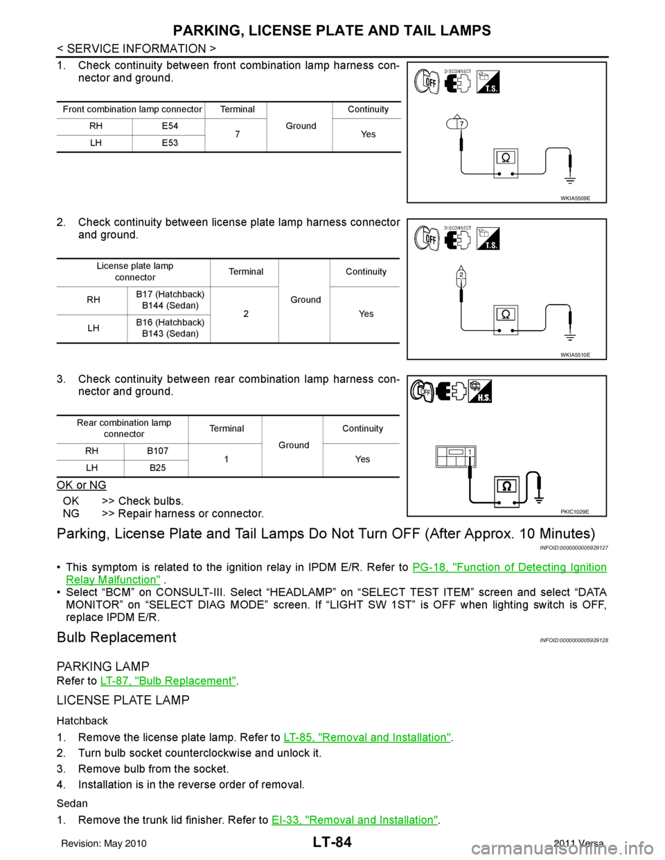
1. Check continuity between front combination lamp harness con-nector and ground.
2. Check continuity between license plate lamp harness connector and ground.
3. Check continuity between rear combination lamp harness con- nector and ground.
OK or NG
OK >> Check bulbs.
NG >> Repair harness or connector.
Parking, License Plate and Tail Lamps Do Not Turn OFF (After Approx. 10 Minutes)
INFOID:0000000005929127
• This symptom is related to the ignition relay in IPDM E/R. Refer to PG-18, "Function of Detecting Ignition
Relay Malfunction" .
• Select “BCM” on CONSULT-III. Select “HEADLAMP” on “SELECT TEST ITEM” screen and select “DATA
MONITOR” on “SELECT DIAG MODE” sc reen. If “LIGHT SW 1ST” is OFF when lighting switch is OFF,
replace IPDM E/R.
Bulb ReplacementINFOID:0000000005929128
PA R K I N G L A M P
Refer to LT-87, "Bulb Replacement".
LICENSE PLATE LAMP
Hatchback
1. Remove the license plate lamp. Refer to LT-85, "Removal and Installation".
2. Turn bulb socket counterclockwise and unlock it.
3. Remove bulb from the socket.
4. Installation is in the reverse order of removal.
Sedan
1. Remove the trunk lid finisher. Refer to EI-33, "Removal and Installation".
Front combination lamp connector Terminal
GroundContinuity
RH E54
7Y es
LH E53
WKIA5509E
License plate lamp
connector Te r m i n a l
GroundContinuity
RH B17 (Hatchback)
B144 (Sedan) 2 Yes
LH B16 (Hatchback)
B143 (Sedan)
WKIA5510E
Rear combination lamp connector Te r m i n a l
GroundContinuity
RH B107
1Y es
LH B25
PKIC1029E
Revision: May 2010 2011 Versa