display NISSAN TIIDA 2011 Service Repair Manual
[x] Cancel search | Manufacturer: NISSAN, Model Year: 2011, Model line: TIIDA, Model: NISSAN TIIDA 2011Pages: 3787, PDF Size: 78.35 MB
Page 1881 of 3787
TROUBLE DIAGNOSISEC-587
< SERVICE INFORMATION > [MR18DE]
C
D
E
F
G H
I
J
K L
M A
EC
NP
O
1. Get the detailed information from the customer about the symptom (the condition and the environment
when the incident/malfunction occurred) using the “Diagnostic Work Sheet”.
2. Ask if the customer requests I/M examination.
Malfunction information, obtained>>GO TO 2.
No malfunction information, but a request for I/M examination>>GO TO 13.
2.CHECK DTC
1. Check DTC.
2. Perform the following procedure if DTC is displayed.
- Record DTC and freeze frame data. (Print them out with CONSULT-III or GST.)
- Erase DTC. (Refer to EC-542, "
Emission-related Diagnostic Information".)
- Study the relationship between the cause detected by DTC and the symptom described by the customer.
(Symptom Table is useful. Refer to EC-592, "
Symptom Matrix Chart".)
3. Check related service bulletins for information.
Are any symptoms described and any DTCs detected?
Symptom is described, DTC is detected>>GO TO 3.
Symptom is described, DTC is not detected>>GO TO 4.
Symptom is not described, DTC is detected>>GO TO 5.
3.CONFIRM THE SYMPTOM
Try to confirm the symptom described by the customer (except MIL ON).
Also study the normal operation and fa il-safe related to the symptom.
Diagnosis Work Sheet is useful to verify the incident.
Verify relation between the symptom and t he condition when the symptom is detected.
>> GO TO 5.
4.CONFIRM THE SYMPTOM
Try to confirm the symptom described by the customer.
Also study the normal operation and fa il-safe related to the symptom.
Diagnosis Work Sheet is useful to verify the incident.
Verify relation between the symptom and t he condition when the symptom is detected.
>> GO TO 6.
5.PERFORM DTC CONFIRMATION PROCEDURE
Perform DTC CONFIRMATION PROCEDURE for the di splayed DTC, and then make sure that DTC is
detected again.
If two or more DTCs are detected, refer to EC-590, "
DTC Inspection Priority Chart" and determine trouble
diagnosis order.
NOTE:
• Freeze frame data is useful if the DTC is not detected.
• Perform Component Function Check if DTC CONF IRMATION PROCEDURE is not included on Service
Manual. This simplified check procedure is an effect ive alternative though DTC cannot be detected during
this check.
If the result of Component Function Check is NG, it is the same as the detection of DTC by DTC CONFIR-
MATION PROCEDURE.
Is DTC detected?
YES >> GO TO 10.
NO >> Check according to EC-624, "
Description".
6.PERFORM BASIC INSPECTION
Perform EC-574, "
Basic Inspection".
Do you have CONSULT-III?
YES >> GO TO 7.
NO >> GO TO 9.
Revision: May 2010 2011 Versa
Page 1882 of 3787
EC-588
< SERVICE INFORMATION >[MR18DE]
TROUBLE DIAGNOSIS
7.PERFORM SPEC IN DATA MONITOR MODE
With CONSULT-III
Make sure that “MAS A/F SE-B1”, “MAS A/F SE-B2”, “B/FUEL SCHDL”, “A/F ALPHA-B1”, and “A/F ALPHA-
B2” are within the SP value using CONSULT-III “SPEC” in “DATA MONITOR” mode. Refer to EC-624, "
Inspec-
tion Procedure".
Is the measurement value within the SP value?
YES >> GO TO 9.
NO >> GO TO 8.
8.DETECT MALFUNCTIONING PART BY TROUBL E DIAGNOSIS - SPECIFICATION VALUE
Detect malfunctioning part according to EC-624, "
Diagnosis Procedure".
Is a malfunctioning part detected?
YES >> GO TO 11.
NO >> GO TO 9.
9.DETECT MALFUNCTIONING SYSTEM BY SYMPTOM TABLE
Detect malfunctioning system according to EC-592, "
Symptom Matrix Chart" based on the confirmed symptom
in step 4, and determine the trouble diagnosis order based on possible causes and symptoms.
>> GO TO 10.
10.DETECT MALFUNCTIONING PA RT BY DIAGNOSIS PROCEDURE
Inspect according to Diagnos is Procedure of the system.
NOTE:
The Diagnosis Procedure in EC section described based on open circuit inspection. A short circuit inspection
is also required for the circuit check in the Diagnosis Procedure. For details, refer to GI-25, "
How to Perform
Efficient Diagnosis for an Electrical Incident".
Is a malfunctioning part detected?
YES >> GO TO 11.
NO >> Monitor input data from related sensors or check voltage of related ECM terminals using CON- SULT-III. Refer to EC-605, "
ECM Terminal and Reference Value", EC-620, "CONSULT-III Refer-
ence Value in Data Monitor Mode".
11 .REPAIR OR REPLACE THE MALFUNCTIONING PART
1. Repair or replace the malfunctioning part.
2. Reconnect parts or connectors disconnected during Diagnosis Procedure again after repair and replace- ment.
3. Check DTC. If DTC is displayed, erase it. Refer to EC-542, "
Emission-related Diagnostic Information".
>> GO TO 12.
12.FINAL CHECK
When DTC was detected in step 2, perform DTC CO NFIRMATION PROCEDURE or Component Function
Check again, and then make sure that the malfunction have been completely repaired.
When symptom was described from the customer, refer to confirmed symptom in step 3 or 4, and make sure
that the symptom is not detected.
Is DTC detected and does symptom remain?
YES-1 >> DTC is detected: GO TO 10.
YES-2 >> Symptom remains: GO TO 6.
NO-1 >> No request for I/M examination from the custom er: Before returning the vehicle to the customer,
always erase unnecessary DTC in ECM and TCM (Transmission Control Module). Refer to EC-
542, "Emission-related Diagnostic Information".
NO-2 >> I/M examination, request ed from the customer: GO TO 13.
13.PREPARE FOR I/M EXAMINATION
1. Set SRT codes. Refer to EC-542, "
Emission-related Diagnostic Information".
2. Erase permanent DTCs. Refer to EC-542, "
Emission-related Diagnostic Information".
Revision: May 2010 2011 Versa
Page 1884 of 3787
EC-590
< SERVICE INFORMATION >[MR18DE]
TROUBLE DIAGNOSIS
DTC Inspection Priority Chart
INFOID:0000000006341731
If some DTCs are displayed at the same time, perform inspections one by one based on the following priority
chart.
Fail-Safe ChartINFOID:0000000006341732
When the DTC listed below is detected, the ECM enters fail-safe mode and the MIL lights up.
Priority Detected items (DTC)
1 • U0101 U0140 U1001 CAN communication line • P0101 P0102 P0103 Mass air flow sensor
• P0112 P0113 P0127 Intake air temperature sensor
• P0116 P0117 P0118 P0125 Engine coolant temperature sensor
• P0122 P0123 P0222 P0223 P1225 P1226 P2135 Throttle position sensor
• P0128 Thermostat function
• P0181 P0182 P0183 Fuel tank temperature sensor
• P0327 P0328 Knock sensor
• P0335 Crankshaft position sensor (POS)
• P0340 Camshaft position sensor (PHASE)
• P0460 P0461 P0462 P0463 Fuel level sensor
• P0500 Vehicle speed sensor
• P0605 P0607 ECM
• P0643 Sensor power supply
• P0705 Transmission range switch
• P0850 Park/neutral position (PNP) switch
• P1610 - P1615 NATS
• P2122 P2123 P2127 P2128 P2138 Accelerator pedal position sensor
2 • P0031 P0032 Air fuel ratio (A/F) sensor 1 heater • P0037 P0038 Heated oxygen sensor 2 heater
• P0075 Intake valve timing control solenoid valve
• P0130 P0131 P0132 P014C P014D P2A00 Air fuel ratio (A/F) sensor 1
• P0137 P0138 P0139 Heated oxygen sensor 2
• P0441 EVAP control system purge flow monitoring
• P0443 P0444 P0445 EVAP canister purge volume control solenoid valve
• P0447 P0448 EVAP canister vent control valve
• P0451 P0452 P0453 EVAP control system pressure sensor
• P1217 Engine over temperature (OVERHEAT)
• P1805 Brake switch
• P2100 P2103 Throttle control motor relay
• P2101 Electric throttle control function
• P2118 Throttle control motor
3 • P0011 Intake valve timing control • P0171 P0172 Fuel injection system function
• P0300 - P0304 Misfire
• P0420 Three way catalyst function
• P0442 P0456 EVAP co ntrol system (SMALL LEAK, VERY SMALL LEAK)
• P0455 EVAP control system (GROSS LEAK)
• P0506 P0507 Idle speed control system
• P050A P050B P050E Cold start control
• P0710 P0715 P0720 P0725 P0731 P0732 P0733 P0734 P0740 P0744 P0745 P0746 P0750 P0755 P0776 P0778 P0840 P0845 P1705 P1740 P1760 P1777 P1778 A/T or CVT related sensors, solenoid valves and switches
• P1148 Closed loop control
• P1211 TCS control unit
• P1212 TCS communication line
• P1564 ASCD steering switch
• P1572 ASCD brake switch
• P1574 ASCD vehicle speed sensor
• P1715 Input speed sensor
• P2119 Electric throttle control actuator
Revision: May 2010 2011 Versa
Page 1885 of 3787
TROUBLE DIAGNOSISEC-591
< SERVICE INFORMATION > [MR18DE]
C
D
E
F
G H
I
J
K L
M A
EC
NP
O
• When there is an open circuit on MIL circuit, the ECM c
annot warn the driver by lighting up MIL when there
is malfunction on engine control system.
Therefore, when electrical controlled throttle and pa rt of ECM related diagnoses are continuously detected
as NG for 5 trips, ECM warns the driver that engine control system malfunctions and MIL circuit is open by
means of operating fail-safe function.
The fail-safe function also operates when above diagnoses except MIL circuit are detected and demands the
driver to repair the malfunction.
DTC No. Detected items Engine operating condition in fail-safe mode
P0102
P0103 Mass air flow sensor circuit Engine speed will not rise more than 2,400 rpm due to the fuel cut.
P0117
P0118 Engine coolant temperature
sensor circuit Engine coolant temperature will be determined by ECM based on the following condi-
tion.
CONSULT-III displays the engine coolant temperature decided by ECM.
Condition Engine coolant temperature decided
(CONSULT-III display)
Just as ignition switch is turned ON
or START 40
°C (104 °F)
Approx. 4 minutes or more after
engine starting. 80
°C (176 °F)
Except as shown above 40 - 80°
C (104 - 176 °F)
(Depends on the time)
When the fail-safe system for engine coolant temperature sensor is activated, the cool-
ing fan operates while engine is running.
P0122
P0123
P0222
P0223
P2135 Throttle position sensor The ECM controls the electric throttle control actuator in regulating the throttle opening
in order for the idle position to be within +10 degrees.
The ECM regulates the opening speed of the throttle valve to be slower than the normal
condition.
So, the acceleration will be poor.
P0643 Sensor power supply ECM stops the electric throttle control actuator control, throttle valve is maintained at a fixed opening (approx. 5 degrees) by the return spring.
P2100
P2103 Throttle control relay ECM stops the electric throttle control actuator control, throttle valve is maintained at a
fixed opening (approx. 5 degrees) by the return spring.
P2101 Electric throttle control func- tion ECM stops the electric throttle control actuator control, throttle valve is maintained at a
fixed opening (approx. 5 degrees) by the return spring.
P2118 Throttle control motor ECM stops the electric throttle control actuator control, throttle valve is maintained at a fixed opening (approx. 5 degrees) by the return spring.
P2119 Electric throttle control actu- ator (When electric throttle control actuator does not function properly due to the return
spring malfunction:)
ECM controls the electric throttle actuator by regulating the throttle opening around the
idle position. The engine speed will not rise more than 2,000 rpm.
(When throttle valve opening angle in fail-safe mode is not in specified range:)
ECM controls the electric throttle control ac
tuator by regulating the throttle opening to
20 degrees or less.
(When ECM detects the throttle valve is stuck open:)
While the vehicle is driving, it slows down gradually by fuel cut. After the vehicle stops,
the engine stalls.
The engine can restart in N or P (A/T, CVT), Neutral (M/T) position, and engine speed
will not exceed 1,000 rpm or more.
P2122
P2123
P2127
P2128
P2138 Accelerator pedal position
sensor
The ECM controls the electric throttle control actuator in regulating the throttle opening
in order for the idle position to be within +10 degrees.
The ECM regulates the opening speed of the throttle valve to be slower than the normal
condition.
So, the acceleration will be poor.
Engine operating condition in fail-safe mode
Engine speed will not rise more than 2,500 rpm due to the fuel cut
Revision: May 2010 2011 Versa
Page 1906 of 3787
EC-612
< SERVICE INFORMATION >[MR18DE]
TROUBLE DIAGNOSIS
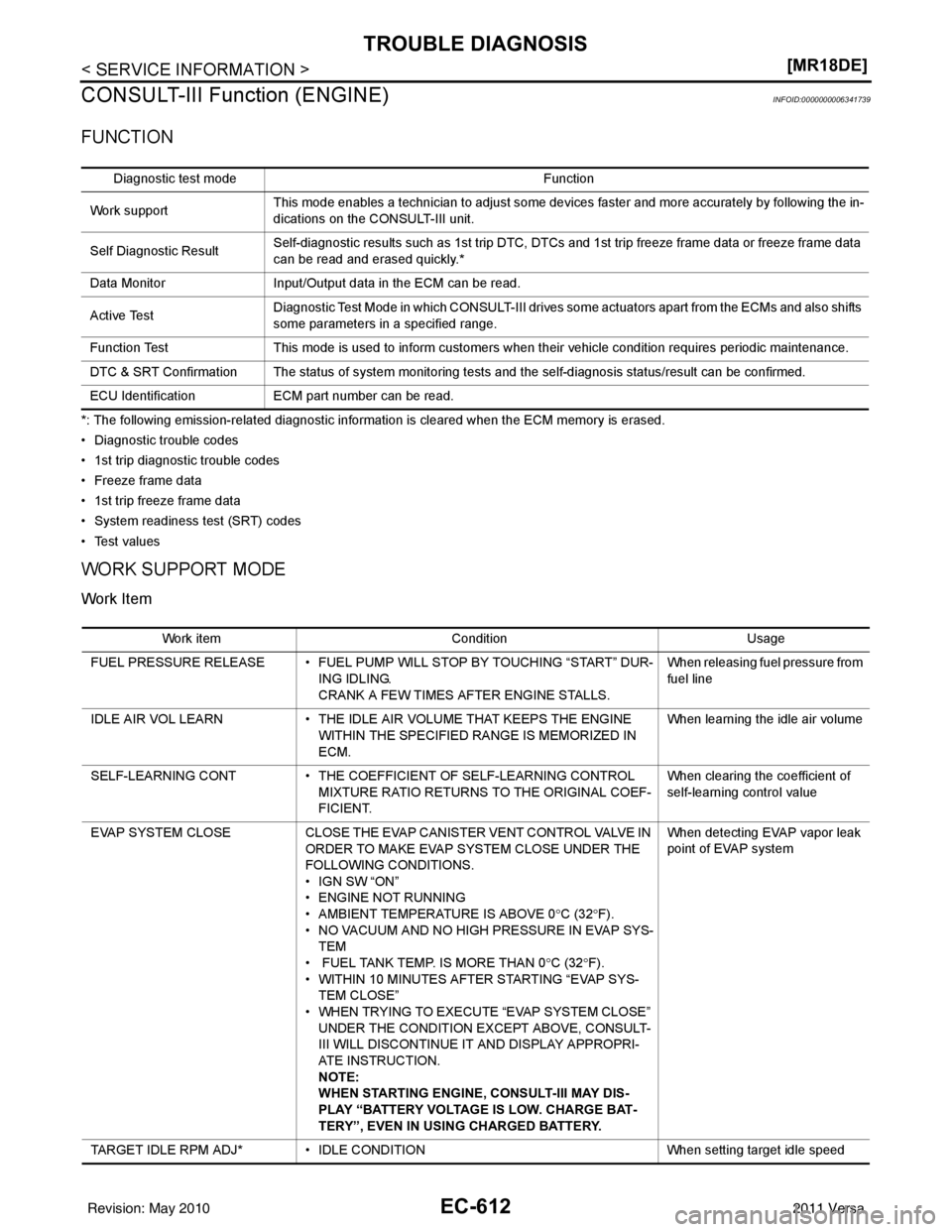
CONSULT-III Function (ENGINE)
INFOID:0000000006341739
FUNCTION
*: The following emission-related diagnostic information is cleared when the ECM memory is erased.
• Diagnostic trouble codes
• 1st trip diagnostic trouble codes
• Freeze frame data
• 1st trip freeze frame data
• System readiness test (SRT) codes
•Test values
WORK SUPPORT MODE
Work Item
Diagnostic test mode Function
Work support This mode enables a technician to adjust some devices faster and more accurately by following the in-
dications on the CONSULT-III unit.
Self Diagnostic Result Self-diagnostic results such as 1st trip DTC, DTCs and 1st trip freeze frame data or freeze frame data
can be read and erased quickly.*
Data Monitor Input/Output data in the ECM can be read.
Active Test Diagnostic Test Mode in which CONSULT-III drives so
me actuators apart from the ECMs and also shifts
some parameters in a specified range.
Function Test This mode is used to inform customers when their vehicle condition requires periodic maintenance.
DTC & SRT Confirmation The status of system monitoring tests and the self-diagnosis status/result can be confirmed.
ECU Identification ECM part number can be read.
Work item Condition Usage
FUEL PRESSURE RELEASE • FUEL PUMP WILL STOP BY TOUCHING “START” DUR- ING IDLING.
CRANK A FEW TIMES AFTER ENGINE STALLS. When releasing fuel pressure from
fuel line
IDLE AIR VOL LEARN • THE IDLE AIR VOLUME THAT KEEPS THE ENGINE
WITHIN THE SPECIFIED RANGE IS MEMORIZED IN
ECM. When learning the idle air volume
SELF-LEARNING CONT • THE COEFFICIENT OF SELF-LEARNING CONTROL
MIXTURE RATIO RETURNS TO THE ORIGINAL COEF-
FICIENT. When clearing the coefficient of
self-learning control value
EVAP SYSTEM CLOSE CLOSE THE EVAP CANISTER VENT CONTROL VALVE IN
ORDER TO MAKE EVAP SYSTEM CLOSE UNDER THE
FOLLOWING CONDITIONS.
•IGN SW “ON”
• ENGINE NOT RUNNING
• AMBIENT TEMPERATURE IS ABOVE 0° C (32°F).
• NO VACUUM AND NO HIGH PRESSURE IN EVAP SYS-
TEM
• FUEL TANK TEMP. IS MORE THAN 0 °C (32 °F).
• WITHIN 10 MINUTES AFTER STARTING “EVAP SYS-
TEM CLOSE”
• WHEN TRYING TO EXECUTE “EVAP SYSTEM CLOSE” UNDER THE CONDITION EXCEPT ABOVE, CONSULT-
III WILL DISCONTINUE IT AND DISPLAY APPROPRI-
ATE INSTRUCTION.
NOTE:
WHEN STARTING ENGINE, CONSULT-III MAY DIS-
PLAY “BATTERY VOLTAGE IS LOW. CHARGE BAT-
TERY”, EVEN IN USING CHARGED BATTERY. When detecting EVAP vapor leak
point of EVAP system
TARGET IDLE RPM ADJ* • IDLE CONDITION When setting target idle speed
Revision: May 2010 2011 Versa
Page 1907 of 3787
TROUBLE DIAGNOSISEC-613
< SERVICE INFORMATION > [MR18DE]
C
D
E
F
G H
I
J
K L
M A
EC
NP
O*: This function is not necessary in the usual service procedure.
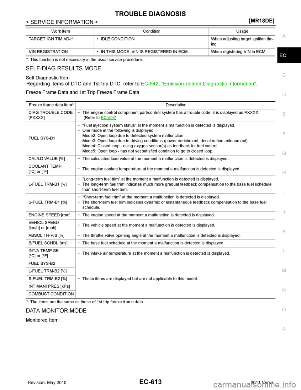
SELF-DIAG RESULTS MODE
Self Diagnostic Item
Regarding items of DTC and 1st trip DTC, refer to EC-542, "Emission-related Diagnostic Information".
Freeze Frame Data and 1st Trip Freeze Frame Data
*: The items are the same as those of 1st trip freeze frame data.
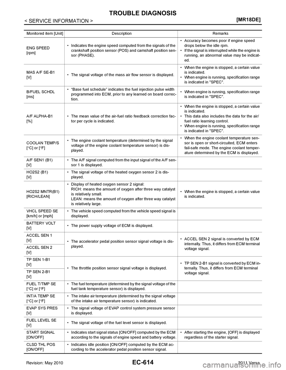
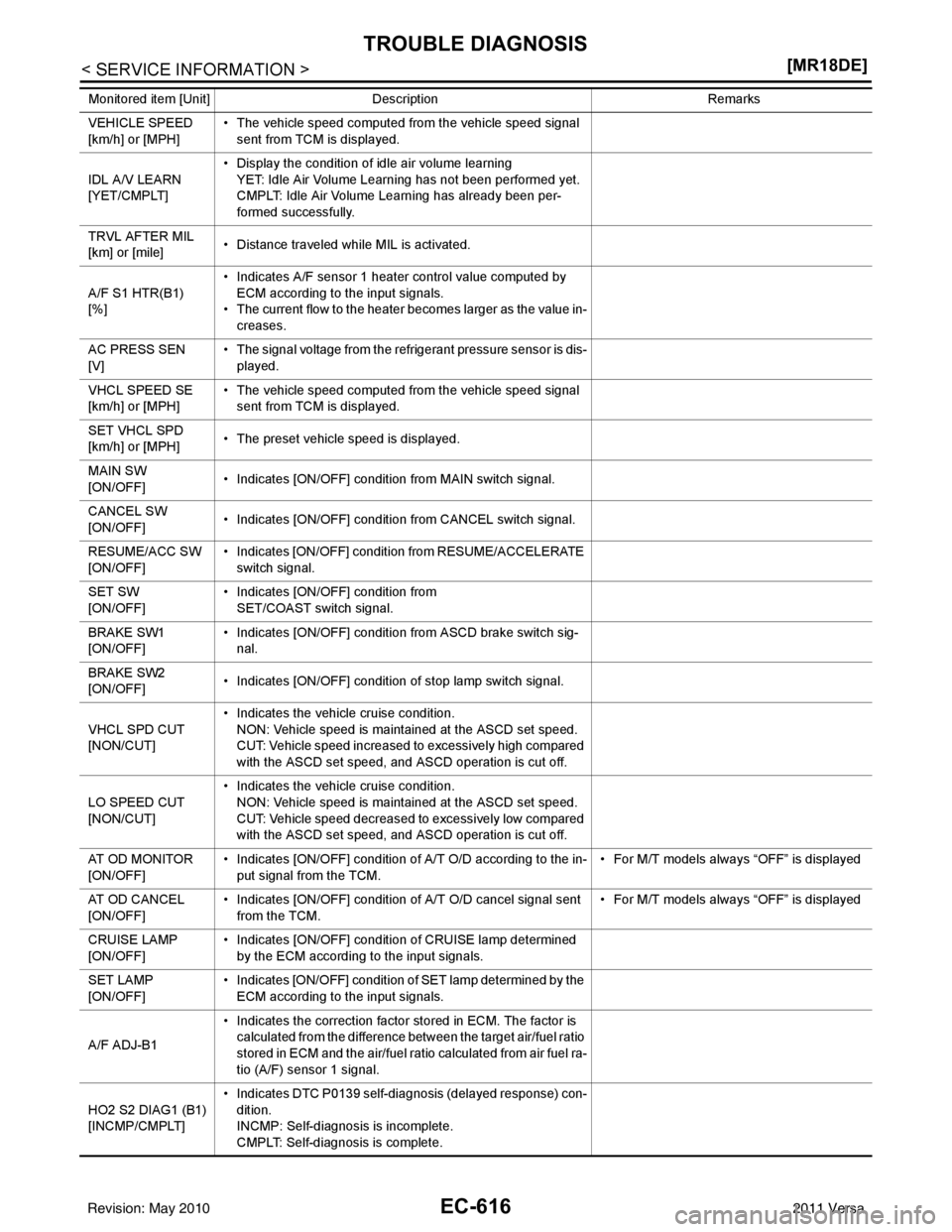
DATA MONITOR MODE
Monitored Item
TARGET IGN TIM ADJ*
• IDLE CONDITION When adjusting target ignition tim-
ing
VIN REGISTRATION • IN THIS MODE, VIN IS REGISTERED IN ECM. When registering VIN in ECM
Work item
Condition Usage
Freeze frame data item* Description
DIAG TROUBLE CODE
[PXXXX] • The engine control com
ponent part/control system has a trouble code, it is displayed as PXXXX.
(Refer to EC-504
)
FUEL SYS-B1 • “Fuel injection system status” at the moment a malfunction is detected is displayed.
• One mode in the following is displayed.
Mode2: Open loop due to detected system malfunction
Mode3: Open loop due to driving conditions (power enrichment, deceleration enleanment)
Mode4: Closed loop - using oxygen sensor(s) as feedback for fuel control
Mode5: Open loop - has not yet satisfied condition to go to closed loop
CAL/LD VALUE [%] • The calculated load value at the moment a malfunction is detected is displayed.
COOLANT TEMP
[ ° C] or [ °F] • The engine coolant temperature at the moment a malfunction is detected is displayed.
L-FUEL TRM-B1 [%] • “Long-term fuel trim” at the moment a malfunction is detected is displayed.
• The long-term fuel trim indicates much more gradual feedback compensation to the base fuel schedule
than short-term fuel trim.
S-FUEL TRM-B1 [%] • “Short-term fuel trim” at the moment a malfunction is detected is displayed.
• The short-term fuel trim indicates dynamic or instantaneous feedback compensation to the base fuel
schedule.
ENGINE SPEED [rpm] • The engine sp eed at the moment a malfunction is de tected is displayed.
VEHICL SPEED
[km/h] or [mph] • The vehicle speed at the moment a malfunction is detected is displayed.
ABSOL TH-P/S [%] • The throttle valve opening angle at the moment a malfunction is detected is displayed.
B/FUEL SCHDL [ms] • The ba se fuel schedule at the moment a malfunction is detected is displayed.
INT/A TEMP SE
[ ° C] or [ °F] • The intake air temperature at the moment a malfunction is detected is displayed.
FUEL SYS-B2
• These items are displayed but are not applicable to this model.
L-FUEL TRM-B2 [%]
S-FUEL TRM-B2 [%]
INT MANI PRES [kPa]
COMBUST CONDITION
Revision: May 2010
2011 Versa
Page 1908 of 3787
EC-614
< SERVICE INFORMATION >[MR18DE]
TROUBLE DIAGNOSIS
Monitored item [Unit]
Description Remarks
ENG SPEED
[rpm] • Indicates the engine speed computed from the signals of the
crankshaft position sensor (POS) and camshaft position sen-
sor (PHASE). • Accuracy becomes poor if engine speed
drops below the idle rpm.
• If the signal is interrupted while the engine is
running, an abnormal value may be indicat-
ed.
MAS A/F SE-B1
[V] • The signal voltage of the mass air flow sensor is displayed. • When the engine is stopped, a certain value
is indicated.
• When engine is running, specification range is indicated in "SPEC".
B/FUEL SCHDL
[ms] • “Base fuel schedule” indicates the fuel injection pulse width
programmed into ECM, prior to any learned on board correc-
tion. • When engine is running, specification range
is indicated in "SPEC".
A/F ALPHA-B1
[%] • The mean value of the air-fuel ratio feedback correction fac-
tor per cycle is indicated. • When the engine is stopped, a certain value
is indicated.
• This data also includes the data for the air/
fuel ratio learning control.
• When engine is running, specification range is indicated in "SPEC".
COOLAN TEMP/S
[ ° C] or [ °F] • The engine coolant temperature (determined by the signal
voltage of the engine coolant temperature sensor) is dis-
played. • When the engine coolant temperature sen-
sor is open or short-circuited, ECM enters
fail-safe mode. The engine coolant temper-
ature determined by the ECM is displayed.
A/F SEN1 (B1)
[V] • The A/F signal computed from the input signal of the A/F sen-
sor 1 is displayed.
HO2S2 (B1)
[V] • The signal voltage of the heated oxygen sensor 2 is dis-
played.
HO2S2 MNTR(B1)
[RICH/LEAN] • Display of heated oxygen sensor 2 signal:
RICH: means the amount of oxygen after three way catalyst
is relatively small.
LEAN: means the amount of oxygen after three way catalyst
is relatively large. • When the engine is stopped, a certain value
is indicated.
VHCL SPEED SE
[km/h] or [mph] • The vehicle speed computed from the vehicle speed signal is
displayed.
BATTERY VOLT
[V] • The power supply voltage of ECM is displayed.
ACCEL SEN 1
[V] • The accelerator pedal position sensor signal voltage is dis-
played. • ACCEL SEN 2 signal is converted by ECM
internally. Thus, it differs from ECM terminal
voltage signal.
ACCEL SEN 2
[V]
TP SEN 1-B1
[V]
• The throttle position sensor signal voltage is displayed. • TP SEN 2-B1 signal is converted by ECM in-
ternally. Thus, it differs from ECM terminal
voltage signal.
TP SEN 2-B1
[V]
FUEL T/TMP SE
[
° C] or [ °F] • The fuel temperature (determined by the signal voltage of the
fuel tank temperature sensor) is displayed.
INT/A TEMP SE
[ ° C] or [ °F] • The intake air temperature (determined by the signal voltage
of the intake air temperature sensor) is indicated.
EVAP SYS PRES
[V ] •
T
he signal voltage of EVAP control system pressure sensor
is displayed.
FUEL LEVEL SE
[V] • The signal voltage of the fuel level sensor is displayed.
START SIGNAL
[ON/OFF] • Indicates start signal status [ON/OFF] computed by the ECM
according to the signals of engine speed and battery voltage. • After starting the engine, [OFF] is displayed
regardless of the starter signal.
CLSD THL POS
[ON/OFF] • Indicates idle position [ON/OFF] computed by the ECM ac-
cording to the accelerator pedal position sensor signal.
Revision: May 2010 2011 Versa
Page 1910 of 3787
EC-616
< SERVICE INFORMATION >[MR18DE]
TROUBLE DIAGNOSIS
VEHICLE SPEED
[km/h] or [MPH]• The vehicle speed computed from the vehicle speed signal
sent from TCM is displayed.
IDL A/V LEARN
[YET/CMPLT] • Display the condition of idle air volume learning
YET: Idle Air Volume Learning has not been performed yet.
CMPLT: Idle Air Volume Learning has already been per-
formed successfully.
TRVL AFTER MIL
[km] or [mile] • Distance traveled while MIL is activated.
A/F S1 HTR(B1)
[%] • Indicates A/F sensor 1 heater control value computed by
ECM according to the input signals.
• The current flow to the heater becomes larger as the value in-
creases.
AC PRESS SEN
[V] • The signal voltage from the refrigerant pressure sensor is dis-
played.
VHCL SPEED SE
[km/h] or [MPH] • The vehicle speed computed from the vehicle speed signal
sent from TCM is displayed.
SET VHCL SPD
[km/h] or [MPH] • The preset vehicle speed is displayed.
MAIN SW
[ON/OFF] • Indicates [ON/OFF] condition from MAIN switch signal.
CANCEL SW
[ON/OFF] • Indicates [ON/OFF] condition from CANCEL switch signal.
RESUME/ACC SW
[ON/OFF] • Indicates [ON/OFF] condition from RESUME/ACCELERATE
switch signal.
SET SW
[ON/OFF] • Indicates [ON/OFF] condition from
SET/COAST switch signal.
BRAKE SW1
[ON/OFF] • Indicates [ON/OFF] condition from ASCD brake switch sig-
nal.
BRAKE SW2
[ON/OFF] • Indicates [ON/OFF] condition of stop lamp switch signal.
VHCL SPD CUT
[NON/CUT] • Indicates the vehicle cruise condition.
NON: Vehicle speed is maintained at the ASCD set speed.
CUT: Vehicle speed increased to excessively high compared
with the ASCD set speed, and ASCD operation is cut off.
LO SPEED CUT
[NON/CUT] • Indicates the vehicle cruise condition.
NON: Vehicle speed is maintained at the ASCD set speed.
CUT: Vehicle speed decreased to excessively low compared
with the ASCD set speed, and ASCD operation is cut off.
AT O D M O N I T O R
[ON/OFF] • Indicates [ON/OFF] condition of A/T O/D according to the in-
put signal from the TCM. • For M/T models always “OFF” is displayed
AT OD CANCEL
[ON/OFF] • Indicates [ON/OFF] condition of A/T O/D cancel signal sent
from the TCM. • For M/T models always “OFF” is displayed
CRUISE LAMP
[ON/OFF] • Indicates [ON/OFF] condition of CRUISE lamp determined
by the ECM according to the input signals.
SET LAMP
[ON/OFF] • Indicates [ON/OFF] condition of SET lamp determined by the
ECM according to the input signals.
A/F ADJ-B1 • Indicates the correction factor stored in ECM. The factor is
calculated from the difference between the target air/fuel ratio
stored in ECM and the air/fuel ratio calculated from air fuel ra-
tio (A/F) sensor 1 signal.
HO2 S2 DIAG1 (B1)
[INCMP/CMPLT] • Indicates DTC P0139 self-diagnosis (delayed response) con-
dition.
INCMP: Self-diagnosis is incomplete.
CMPLT: Self-diagnosis is complete.
Monitored item [Unit]
Description Remarks
Revision: May 2010 2011 Versa
Page 1911 of 3787
TROUBLE DIAGNOSISEC-617
< SERVICE INFORMATION > [MR18DE]
C
D
E
F
G H
I
J
K L
M A
EC
NP
O
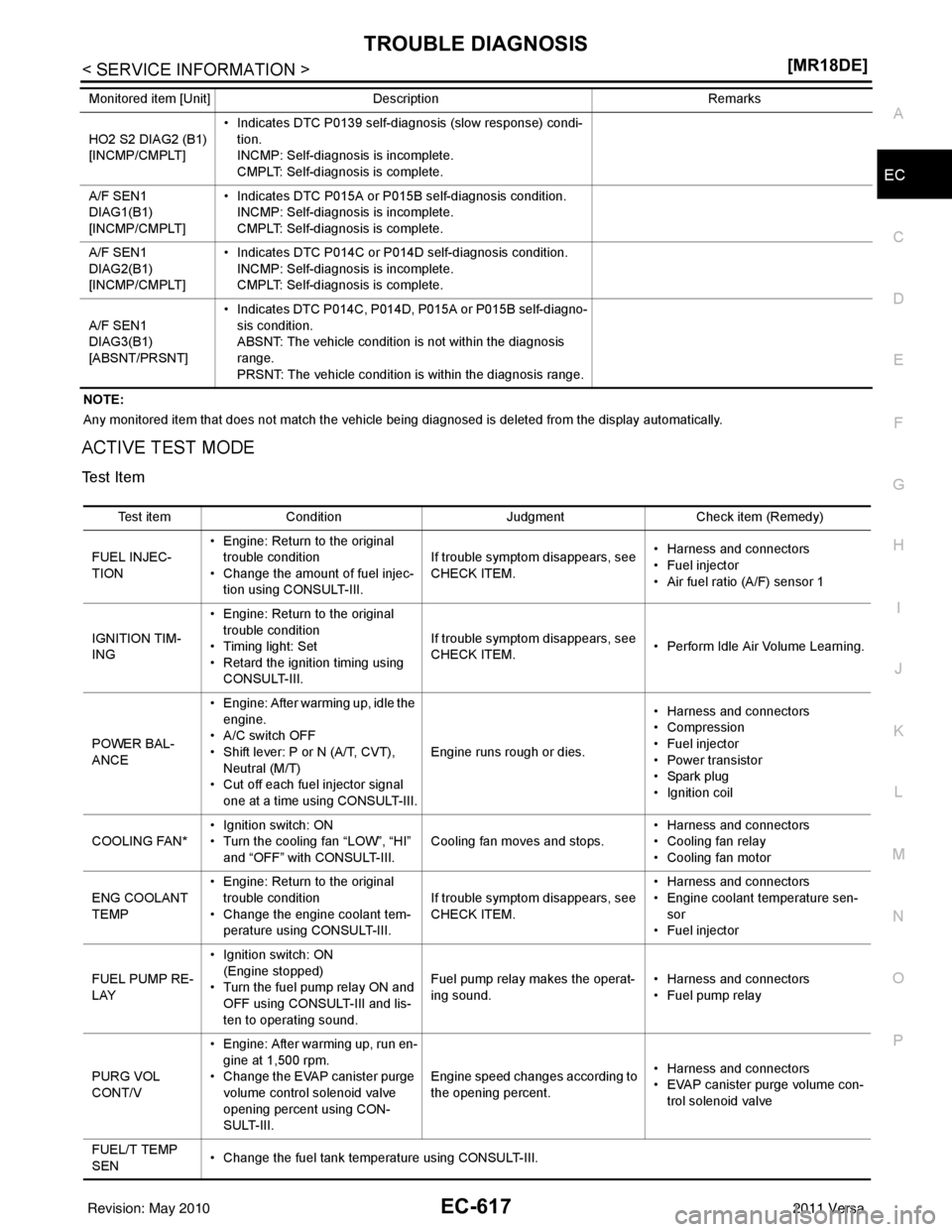
NOTE:
Any monitored item that does not match the vehicle being diagnosed is deleted from the display automatically.
ACTIVE TEST MODE
Test Item
HO2 S2 DIAG2 (B1)
[INCMP/CMPLT]
• Indicates DTC P0139 self-diagnosis (slow response) condi-
tion.
INCMP: Self-diagnosis is incomplete.
CMPLT: Self-diagnosis is complete.
A/F SEN1
DIAG1(B1)
[INCMP/CMPLT] • Indicates DTC P015A or P015B self-diagnosis condition.
INCMP: Self-diagnosis is incomplete.
CMPLT: Self-diagnosis is complete.
A/F SEN1
DIAG2(B1)
[INCMP/CMPLT] • Indicates DTC P014C or P014D self-diagnosis condition.
INCMP: Self-diagnosis is incomplete.
CMPLT: Self-diagnosis is complete.
A/F SEN1
DIAG3(B1)
[ABSNT/PRSNT] • Indicates DTC P014C, P014D, P015A or P015B self-diagno-
sis condition.
ABSNT: The vehicle condition is not within the diagnosis
range.
PRSNT: The vehicle condition is within the diagnosis range.
Monitored item [Unit]
Description Remarks
Test itemCondition JudgmentCheck item (Remedy)
FUEL INJEC-
TION • Engine: Return to the original
trouble condition
• Change the amount of fuel injec- tion using CONSULT-III. If trouble symptom disappears, see
CHECK ITEM.
• Harness and connectors
• Fuel injector
• Air fuel ratio (A/F) sensor 1
IGNITION TIM-
ING • Engine: Return to the original
trouble condition
• Timing light: Set
• Retard the ignition timing using CONSULT-III. If trouble symptom disappears, see
CHECK ITEM.
• Perform Idle Air Volume Learning.
POWER BAL-
ANCE • Engine: After warming up, idle the
engine.
• A/C switch OFF
• Shift lever: P or N (A/T, CVT), Neutral (M/T)
• Cut off each fuel injector signal one at a time using CONSULT-III. Engine runs rough or dies.
• Harness and connectors
• Compression
• Fuel injector
• Power transistor
•Spark plug
• Ignition coil
COOLING FAN* • Ignition switch: ON
• Turn the cooling fan “LOW”, “HI”
and “OFF” with CONSULT-III. Cooling fan moves and stops.
• Harness and connectors
• Cooling fan relay
• Cooling fan motor
ENG COOLANT
TEMP • Engine: Return to the original
trouble condition
• Change the engine coolant tem-
perature using CONSULT-III. If trouble symptom disappears, see
CHECK ITEM. • Harness and connectors
• Engine coolant temperature sen-
sor
• Fuel injector
FUEL PUMP RE-
LAY • Ignition switch: ON
(Engine stopped)
• Turn the fuel pump relay ON and
OFF using CONSULT-III and lis-
ten to operating sound. Fuel pump relay makes the operat-
ing sound.
• Harness and connectors
• Fuel pump relay
PURG VOL
CONT/V • Engine: After warming up, run en-
gine at 1,500 rpm.
• Change the EVAP canister purge volume control solenoid valve
opening percent using CON-
SULT-III. Engine speed changes according to
the opening percent.
• Harness and connectors
• EVAP canister purge volume con-
trol solenoid valve
FUEL/T TEMP
SEN • Change the fuel tank temperature using CONSULT-III.
Revision: May 2010
2011 Versa
Page 1916 of 3787
EC-622
< SERVICE INFORMATION >[MR18DE]
TROUBLE DIAGNOSIS
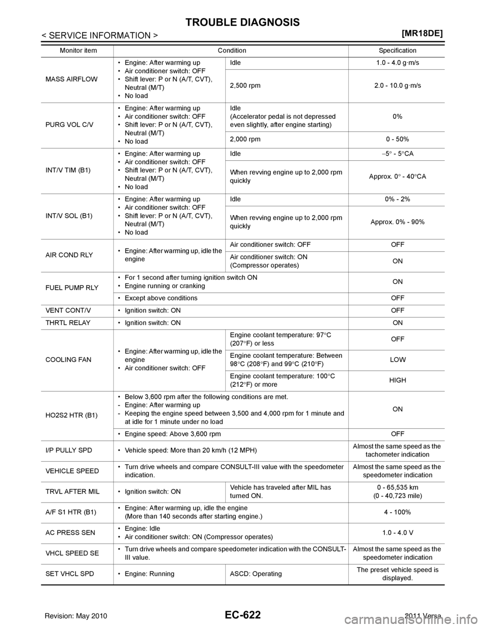
MASS AIRFLOW• Engine: After warming up
• Air conditioner switch: OFF
• Shift lever: P or N (A/T, CVT),
Neutral (M/T)
•No load Idle
1.0 - 4.0 g·m/s
2,500 rpm 2.0 - 10.0 g·m/s
PURG VOL C/V • Engine: After warming up
• Air conditioner switch: OFF
• Shift lever: P or N (A/T, CVT),
Neutral (M/T)
•No load Idle
(Accelerator pedal is not depressed
even slightly, after engine starting)
0%
2,000 rpm 0 - 50%
INT/V TIM (B1) • Engine: After warming up
• Air conditioner switch: OFF
• Shift lever: P or N (A/T, CVT),
Neutral (M/T)
•No load Idle
−5 ° - 5 °CA
When revving engine up to 2,000 rpm
quickly Approx. 0
° - 40 °CA
INT/V SOL (B1) • Engine: After warming up
• Air conditioner switch: OFF
• Shift lever: P or N (A/T, CVT),
Neutral (M/T)
•No load Idle
0% - 2%
When revving engine up to 2,000 rpm
quickly Approx. 0% - 90%
AIR COND RLY • Engine: After warming up, idle the
engine Air conditioner switch: OFF
OFF
Air conditioner switch: ON
(Compressor operates) ON
FUEL PUMP RLY • For 1 second after turning ignition switch ON
• Engine running or cranking
ON
• Except above conditions OFF
VENT CONT/V • Ignition switch: ON OFF
THRTL RELAY • Ignition switch: ON ON
COOLING FAN • Engine: After warming up, idle the
engine
• Air conditioner switch: OFF Engine coolant temperature: 97
°C
(207 °F) or less OFF
Engine coolant temperature: Between
98 °C (208 °F) and 99 °C (210 °F) LOW
Engine coolant temperature: 100 °C
(212 °F) or more HIGH
HO2S2 HTR (B1) • Below 3,600 rpm after the following conditions are met.
- Engine: After warming up
- Keeping the engine speed between 3,500 and 4,000 rpm for 1 minute and
at idle for 1 minute under no load ON
• Engine speed: Above 3,600 rpm OFF
I/P PULLY SPD • Vehicle speed: More than 20 km/h (12 MPH) Almost the same speed as the
tachometer indication
VEHICLE SPEED • Turn drive wheels and compare CONSULT-III value with the speedometer
indication. Alm
os
t
the same speed as the
speedometer indication
TRVL AFTER MIL • Ignition switch: ON Vehicle has traveled after MIL has
turned ON.0 - 65,535 km
(0 - 40,723 mile)
A/F S1 HTR (B1) • Engine: After warming up, idle the engine
(More than 140 seconds after starting engine.) 4 - 100%
AC PRESS SEN • Engine: Idle
• Air conditioner switch: ON (Compressor operates) 1.0 - 4.0 V
VHCL SPEED SE • Turn drive wheels and compare speedometer indication with the CONSULT-
III value. Almost the same speed as the
speedometer indication
SET VHCL SPD • Engine: Ru nningASCD: Operating The preset vehicle speed is
displayed.
Monitor item
Condition Specification
Revision: May 2010 2011 Versa