power steering NISSAN TIIDA 2011 Service Owner's Manual
[x] Cancel search | Manufacturer: NISSAN, Model Year: 2011, Model line: TIIDA, Model: NISSAN TIIDA 2011Pages: 3787, PDF Size: 78.35 MB
Page 475 of 3787
![NISSAN TIIDA 2011 Service Owners Manual AV-78
< SERVICE INFORMATION >[AUDIO WITH NAVIGATION]
TELEPHONE
When a cellular telephone or the Bluetooth control uni
t is replaced, the telephone must be paired with the
Bluetooth control unit. Diffe](/img/5/57396/w960_57396-474.png "NISSAN TIIDA 2011 Service Owners Manual AV-78
< SERVICE INFORMATION >[AUDIO WITH NAVIGATION]
TELEPHONE
When a cellular telephone or the Bluetooth control uni
t is replaced, the telephone must be paired with the
Bluetooth control unit. Diffe")
AV-78
< SERVICE INFORMATION >[AUDIO WITH NAVIGATION]
TELEPHONE
When a cellular telephone or the Bluetooth control uni
t is replaced, the telephone must be paired with the
Bluetooth control unit. Different cellular telephones may have different pairing procedures. Refer to the cellular
telephone operating manual.
Bluetooth Telephone System Diagram
Bluetooth Control Unit
When the ignition switch is turned to ACC or ON, the Bluetooth control unit will power up. During power up, the
Bluetooth control unit is initialized and performs various self checks. Initialization may take up to 20 seconds. If
a phone is present in the vehicle and paired with the Bl uetooth control unit, Nissan Voice Recognition will then
become active. Bluetooth telephone functions can be tur ned off using the Nissan Voice Recognition system.
For Bluetooth control unit location, refer to AV-77, "
Component Parts and Harness Connector Location".
Steering Wheel Audio Control Switches
When buttons on the steering wheel audio control switch are pushed, the resistance in steering wheel audio
control switch circuit changes depending on which button is pushed. The Bluetooth control module uses this
signal to perform various functions while navigating through the voice recognition system.
The following functions can be performed using the steering wheel audio control switch:
• Initiate Self Diagnosis of the Bluetooth telephone system
• Start a voice recognition session
• Answer and end telephone calls
• Adjust the volume of calls
Volume Switch
Call volume can be adjusted using the AV control unit volume switch.
Bluetooth Microphone
The Bluetooth microphone is located in the roof console assembly. The Bluetooth microphone sends a signal
to the Bluetooth control unit. The Bluetooth microphone c an be actively tested during self-diagnosis. For Blue-
tooth microphone location, refer to AV-77, "
Component Parts and Harness Connector Location".
AV Control Unit
The AV control unit receives signals from the Bluet ooth control unit and sends audio signals to the speakers.
AWNIA2191GB
Revision: May 2010 2011 Versa
Page 480 of 3787
![NISSAN TIIDA 2011 Service Owners Manual TELEPHONEAV-83
< SERVICE INFORMATION > [AUDIO WITH NAVIGATION]
C
D
E
F
G H
I
J
L
M A
B
AV
N
O P
WorkflowINFOID:0000000006216720
Power Supply and Ground Cir cuit Inspection for Bluetooth Control UnitIN](/img/5/57396/w960_57396-479.png "NISSAN TIIDA 2011 Service Owners Manual TELEPHONEAV-83
< SERVICE INFORMATION > [AUDIO WITH NAVIGATION]
C
D
E
F
G H
I
J
L
M A
B
AV
N
O P
WorkflowINFOID:0000000006216720
Power Supply and Ground Cir cuit Inspection for Bluetooth Control UnitIN")
TELEPHONEAV-83
< SERVICE INFORMATION > [AUDIO WITH NAVIGATION]
C
D
E
F
G H
I
J
L
M A
B
AV
N
O P
WorkflowINFOID:0000000006216720
Power Supply and Ground Cir cuit Inspection for Bluetooth Control UnitINFOID:0000000006216721
1.CHECK FUSES
Make sure the following fuses for the Bluetooth control unit are not blown.
OK or NG
OK >> GO TO 2.
NG >> If fuse is blown, be sure to eliminate cause of malfunction before installing new fuse. Refer to PG-
6, "Wiring Diagram - POWER -".
2.CHECK POWER SUPPLY CIRCUIT
1. Disconnect Bluetooth control unit connector B121.
2. Check voltage between connector terminals and ground as fol- lows.
OK or NG
OK >> GO TO 3.
NG >> Check harness for open between Bluetooth control unit and fuse.
3.CHECK GROUND CIRCUITS
1. Turn ignition switch OFF.
Failure Message Action
“Internal failure” Replace Bluetooth control unit. Refer to AV- 8 6 , "
Removal and Installation".
“Bluetooth antenna open” 1. Inspect harness connection.
2. Replace Bluetooth antenna. Refer to AV- 8 6 , "
Removal and Installation".
“Bluetooth antenna shorted”
“Phone/Send for Hands Free System is stuck” Check steering wheel audio control switches. Refer to AV- 6 9 , "
Steering Switch
Check".
“Phone/End for the Hands Free System is stuck”
“Microphone test” (fai led interactive test) 1. Inspect harness between Bluetooth control unit and microphone.
2. Replace microphone. Refer to
AV-86, "
Removal and Installation".
Te r m i n a l s
Ignition Switch Fuse No.
Connector Terminal
B121 1
All positions27
2 ACC/ON20
3 ON/START3
Terminals Ignition switch position
(+) (–) OFF ACC ON
Connector Terminal
B121 1
Ground Battery
voltage Battery
voltage Battery
voltage
20 VBattery
voltage Battery
voltage
30 V0V Battery
voltage
WKIA4389E
Revision: May 2010 2011 Versa
Page 481 of 3787
![NISSAN TIIDA 2011 Service Owners Manual AV-84
< SERVICE INFORMATION >[AUDIO WITH NAVIGATION]
TELEPHONE
2. Check continuity between the following Bluetooth control unit
terminals and ground.
OK or NG
OK >> Inspection End.
NG >> Repair or rep](/img/5/57396/w960_57396-480.png "NISSAN TIIDA 2011 Service Owners Manual AV-84
< SERVICE INFORMATION >[AUDIO WITH NAVIGATION]
TELEPHONE
2. Check continuity between the following Bluetooth control unit
terminals and ground.
OK or NG
OK >> Inspection End.
NG >> Repair or rep")
AV-84
< SERVICE INFORMATION >[AUDIO WITH NAVIGATION]
TELEPHONE
2. Check continuity between the following Bluetooth control unit
terminals and ground.
OK or NG
OK >> Inspection End.
NG >> Repair or replace harness.
Steering Wheel Audio Control Switch Does Not OperateINFOID:0000000006216722
Refer to AV-69, "Steering Switch Check".
Voice Activated Control Function Does Not OperateINFOID:0000000006216723
NOTE:
Even under the normal condition, Bluetooth voice gui dance may not occur when pressing steering wheel
audio control switch.
BLUETOOTH VOICE GUIDANCE IS HEARD WH EN PRESSING STEERING WHEEL AUDIO CON-
TROL SWITCH
1.CHECK HARNESS BETWEEN BLUETOOTH CONT ROL UNIT AND BLUETOOTH MICROPHONE
1. Turn ignition switch OFF.
2. Disconnect Bluetooth control unit connector and Bluetooth microphone connector.
3. Check continuity between Bluetooth control unit connector B121 (A) and Bluetooth microphone connector R15 (B).
4. Check continuity between Bluetooth control unit harness con- nector B121 and ground.
OK or NG
OK >> GO TO 2.
NG >> Repair harness or connector.
2.CHECK BLUETOOTH MICROPHONE POWER SUPPLY
1. Connect Bluetooth control unit connector and Bluetooth microphone connector.
2. Turn ignition switch ON.
Te r m i n a l s Continuity
Connector Terminal—
B121 4
Ground Yes
21
27
AWNIA2213ZZ
Te r m i n a l s
Continuity
Connector Terminal Connector Terminal
A: B121 7
B: R15 1
Ye s
82
29 4
Te r m i n a l s Continuity
Connector Terminal —
A: B121 7
Ground No
8
29
WKIA5795E
Revision: May 2010 2011 Versa
Page 491 of 3787

BCS-1
ELECTRICAL
C
DE
F
G H
I
J
L
M
SECTION BCS
A
B
BCS
N
O P
CONTENTS
BODY CONTROL SYSTEM
SERVICE INFORMATION .. ..........................2
PRECAUTIONS .............................................. .....2
Precaution for Supplemental Restraint System
(SRS) "AIR BAG" and "SEAT BELT PRE-TEN-
SIONER" ............................................................. ......
2
Precaution Necessary for Steering Wheel Rota-
tion After Battery Disconnect ............................... ......
2
BCM (BODY CONTROL MODULE) ....................4
System Description ............................................. ......4
CAN Communication System Description .................8
Schematic ............................................................ .....9
BCM Terminal Arrangement ....................................11
Terminal and Reference Value for BCM ..................12
BCM Power Supply and Ground Circuit Inspection
....
16
CONSULT-III Function (BCM) .................................17
CAN Communication Inspection Using CON-
SULT-III (Self-Diagnosis) ..................................... ....
18
Configuration ...........................................................19
Removal and Installation of BCM ............................19
Revision: May 2010 2011 Versa
Page 492 of 3787

BCS-2
< SERVICE INFORMATION >
PRECAUTIONS
SERVICE INFORMATION
PRECAUTIONS
Precaution for Supplemental Restraint System (SRS) "AIR BAG" and "SEAT BELT
PRE-TENSIONER"
INFOID:0000000005929254
The Supplemental Restraint System such as “A IR BAG” and “SEAT BELT PRE-TENSIONER”, used along
with a front seat belt, helps to reduce the risk or severity of injury to the driver and front passenger for certain
types of collision. This system includes seat belt switch inputs and dual stage front air bag modules. The SRS
system uses the seat belt switches to determine the front air bag deployment, and may only deploy one front
air bag, depending on the severity of a collision and w hether the front occupants are belted or unbelted.
Information necessary to service the system safely is included in the SRS and SB section of this Service Man-
ual.
WARNING:
• To avoid rendering the SRS inopera tive, which could increase the risk of personal injury or death in
the event of a collision which would result in air bag inflation, all maintenance must be performed by
an authorized NISSAN/INFINITI dealer.
• Improper maintenance, including incorrect removal and installation of the SRS can lead to personal
injury caused by unintent ional activation of the system. For re moval of Spiral Cable and Air Bag
Module, see the SRS section.
• Do not use electrical test equipmen t on any circuit related to the SRS unless instructed to in this
Service Manual. SRS wiring harn esses can be identified by yellow and/or orange harnesses or har-
ness connectors.
PRECAUTIONS WHEN USING POWER TOOLS (AIR OR ELECTRIC) AND HAMMERS
WARNING:
• When working near the Airbag Diagnosis Sensor Unit or other Airbag System sensors with the Igni-
tion ON or engine running, DO NOT use air or electri c power tools or strike near the sensor(s) with a
hammer. Heavy vibration could activate the sensor( s) and deploy the air bag(s), possibly causing
serious injury.
• When using air or electric power tools or hammers , always switch the Ignition OFF, disconnect the
battery, and wait at least 3 minu tes before performing any service.
Precaution Necessary for Steering W heel Rotation After Battery Disconnect
INFOID:0000000006413290
NOTE:
• This Procedure is applied only to models with Intelligent Key system and NATS (NISSAN ANTI-THEFT SYS-
TEM).
• Remove and install all control units after disconnecting both battery cables with the ignition knob in the
″LOCK ″ position.
• Always use CONSULT-III to perform self-diagnosis as a part of each function inspection after finishing work.
If DTC is detected, perform trouble diagnosis according to self-diagnostic results.
For models equipped with the Intelligent Key system and NATS, an electrically controlled steering lock mech-
anism is adopted on the key cylinder.
For this reason, if the battery is disconnected or if the battery is discharged, the steering wheel will lock and
steering wheel rotation will become impossible.
If steering wheel rotation is required when battery pow er is interrupted, follow the procedure below before
starting the repair operation.
OPERATION PROCEDURE
1. Connect both battery cables. NOTE:
Supply power using jumper cables if battery is discharged.
2. Use the Intelligent Key or mechanical key to turn the ignition switch to the ″ACC ″ position. At this time, the
steering lock will be released.
3. Disconnect both battery cables. The steering lock will remain released and the steering wheel can be rotated.
4. Perform the necessary repair operation.
Revision: May 2010 2011 Versa
Page 511 of 3787

BL-1
BODY
C
DE
F
G H
J
K L
M
SECTION BL
A
B
BL
N
O P
CONTENTS
BODY, LOCK & SECURITY SYSTEM
SERVICE INFORMATION .. ..........................4
PRECAUTIONS .............................................. .....4
Precaution for Supplemental Restraint System
(SRS) "AIR BAG" and "SEAT BELT PRE-TEN-
SIONER" ............................................................. ......
4
Precaution Necessary for Steering Wheel Rota-
tion After Battery Disconnect ............................... ......
4
Precaution for Procedure without Cowl Top Cover ......5
Precaution for Work ..................................................5
PREPARATION ...................................................6
Special Service Tool ........................................... ......6
Commercial Service Tool ..........................................6
SQUEAK AND RATTLE TROUBLE DIAG-
NOSES ................................................................
7
Work Flow ........................................................... ......7
Generic Squeak and Rattle Troubleshooting ............9
Diagnostic Worksheet .............................................11
HOOD .................................................................13
Fitting Adjustment ............................................... ....13
Removal and Installation .........................................14
Removal and Installation of Hood Lock Control .. ....15
Hood Lock Control Inspection .................................17
RADIATOR CORE SUPPORT ....................... ....19
Removal and Installation .........................................19
FRONT FENDER ................................................21
Removal and Installation .........................................21
POWER DOOR LOCK SYSTEM .................... ....22
Component Parts and Harness Connector Loca-
tion ...................................................................... ....
22
System Description .................................................23
CAN Communication System Description ...............25
Schematic ...............................................................26
Wiring Diagram - D/LOCK - .....................................27
Schematic ...............................................................31
Wiring Diagram - D/LOCK - .....................................32
Terminal and Reference Value for BCM ..................37
Work Flow ............................................................ ....41
CONSULT-III Function (BCM) .................................41
Trouble Diagnosis Symptom Chart ...................... ....43
BCM Power Supply and Ground Circuit Inspection
....
43
Door Switch Check (Hatchback) ..............................44
Door Switch Check (Sedan) ....................................47
Key Switch (Insert) Check .......................................48
Door Lock and Unlock Switch Check ......................49
Front Door Lock Assembly LH (Actuator) Check .....52
Front Door Lock Assembly RH (Actuator) Check ....53
Rear Door Lock Actuator LH/RH Check .............. ....54
Front Door Lock Assembly LH (Key Cylinder
Switch) Check ..........................................................
54
Passenger Select Unlock Relay Circuit Inspection
(With Intelligent Key) ........................................... ....
56
REMOTE KEYLESS ENTRY SYSTEM .............58
Component Parts and Harness Connector Loca-
tion ...........................................................................
58
System Description ..................................................58
CAN Communication System Description ...............60
Schematic ................................................................61
Wiring Diagram - KEYLES - ....................................62
Terminal and Reference Value for BCM ..................65
How to Perform Trouble Diagnosis ...................... ....69
Preliminary Check ...................................................69
CONSULT-III Function (BCM) .................................69
Work Flow ............................................................ ....71
Trouble Diagnosis Symptom Chart ..........................71
Keyfob Battery and Function Check ........................72
ACC Switch Circuit Check .......................................74
Door Switch Check (Hatchback) ..............................74
Door Switch Check (Sedan) ....................................76
Key Switch (Insert) Check .......................................78
Hazard Function Check ...........................................79
Horn Function Check ...............................................79
Interior Lamp and Ignition Keyhole Illumination
Function Check ........................................................
80
Remote Keyless Entry Receiver Check ...................80
Revision: May 2010 2011 Versa
Page 512 of 3787

BL-2
Keyfob Function (Lock) Check ...............................82
Keyfob Function (Unlock) Check ............................82
ID Code Entry Procedure .................................... ...83
Keyfob Battery Replacement ............................... ...85
Removal and Installation of Remote Keyless Entry
Receiver .............................................................. ...
85
INTELLIGENT KEY SYSTEM ............................86
Component Parts and Harness Connector Loca-
tion ....................................................................... ...
86
System Description .................................................88
CAN Communication System Description ..............95
Schematic ............................................................ ...96
Wiring Diagram - I/KEY - ..................................... ...98
Intelligent Key Unit Har ness Connector Terminal
Layout .................................................................. ..
108
Terminal and Reference Value for Intelligent Key
Unit ........................................................................
108
Steering Lock Solenoid Harness Connector Ter-
minal Layout ..........................................................
110
Terminal and Reference Value for Steering Lock
Solenoid .................................................................
110
Terminal and Reference Value for BCM ................111
Trouble Diagnosis Procedure ................................115
CONSULT-III Functions (INTELLIGENT KEY) ......117
CONSULT-III Application Item ............................. ..117
Trouble Diagnosis Symptom Chart ........................119
CAN Communication System Inspection ...............126
Power Supply and Ground Circuit Inspection ........126
Key Switch (Intelligent Key Unit Input) Check .......127
Key Switch (BCM Input) Check .............................128
Ignition Knob Switch Check ................................. ..129
Door Switch Check (Hatchback) ............................131
Door Switch Check (Sedan) ..................................134
Door Request Switch Check ..................................135
Back Door Request Switch Check (Hatchback) ....137
Trunk Opener Request Switch Check (Sedan) ... ..138
Unlock Sensor Check ............................................140
Intelligent Key Warning Buzzer(s) Check ..............142
Outside Key Antenna (Dri ver Side and Passenger
Side) Check ......................................................... ..
143
Outside Key Antenna (Rear Bumper) Check .........144
Inside Key Antenna Check ....................................146
Steering Lock Solenoid Check ............................ ..147
Key Interlock Solenoid (With M/T) Check ..............149
Ignition Switch Position Check ............................ ..150
Stop Lamp Switch Check (With CVT or A/T) ....... ..150
Stop Lamp Switch Check (With M/T) .....................152
CVT or A/T Shift Selector (Park Position Switch)
Check .................................................................. ..
153
"P-SHIFT" Warning Lamp (With CVT or A/T)
Check ....................................................................
154
"LOCK" Warning Lamp (With M/T) Check .............155
"KEY" Warning Lamp (RED) Check ......................155
"KEY" Warning Lamp (G REEN) Check .................155
Check Warning Chime in Combination Meter ........156
Hazard Function Check .........................................156
Horn Function Check .... .........................................157
Headlamp Function Chec k ....................................157
Intelligent Key Battery Re placement .....................158
Remote Keyless Entry Func tion ............................158
Removal and Installation of Intelligent Key Unit ... .158
DOOR ...............................................................160
Fitting Adjustment ................................................ .160
Removal and Installation .......................................163
Back Door Stay Disposal ..................................... .166
FRONT DOOR LOCK .......................................167
Component Parts Location .................................. .167
Removal and Installation .......................................167
REAR DOOR LOCK ....................................... ..170
Component Parts Location .................................. .170
Removal and Installation .......................................170
BACK DOOR LOCK ....................................... ..173
Component Parts and Harness Connector Loca-
tion ....................................................................... .
173
System Description ...............................................173
Wiring Diagram - B/DOOR - ..................................174
Terminal and Reference Value for BCM ...............176
Terminal and Reference Value for Intelligent Key
Unit ....................................................................... .
180
CONSULT-III Function (BCM) ..............................182
Work Flow .............................................................183
Trouble Diagnosis Chart by Symptom ..................183
BCM Power Supply and Ground Circuit Inspection
.
183
Check Back Door Opener Switch Circuit (Without
Intelligent Key or Power Windows) ...................... .
184
Check Back Door Opener Switch Circuit (Without
Intelligent Key, with Power Windows) .................. .
187
Check Back Door Opener Switch Circuit (With In-
telligent Key) ........................................................ .
189
Check Back Door Lock Assembly (Actuator) Cir-
cuit ........................................................................
191
Removal and Installation .......................................193
TRUNK LID ..................................................... ..195
Fitting Adjustment ................................................ .195
Trunk Lid Assembly ..............................................195
Trunk Lid Lock ......................................................196
Trunk Lid Striker ....................................................196
TRUNK LID OPENER .......................................198
Component Parts and Harness Connector Loca-
tion ....................................................................... .
198
System Description ...............................................198
Wiring Diagram - TLID - ........................................199
Terminal and Reference Value for BCM ...............201
Terminal and Reference Value for Intelligent Key
Unit ....................................................................... .
205
CONSULT-III Function (BCM) ..............................207
Work Flow .............................................................208
Trouble Diagnosis Chart by Symptom ..................208
BCM Power Supply and Ground Circuit Inspection
.
208
Revision: May 2010 2011 Versa
Page 514 of 3787

BL-4
< SERVICE INFORMATION >
PRECAUTIONS
SERVICE INFORMATION
PRECAUTIONS
Precaution for Supplemental Restraint System (SRS) "AIR BAG" and "SEAT BELT
PRE-TENSIONER"
INFOID:0000000005929267
The Supplemental Restraint System such as “A IR BAG” and “SEAT BELT PRE-TENSIONER”, used along
with a front seat belt, helps to reduce the risk or severity of injury to the driver and front passenger for certain
types of collision. This system includes seat belt switch inputs and dual stage front air bag modules. The SRS
system uses the seat belt switches to determine the front air bag deployment, and may only deploy one front
air bag, depending on the severity of a collision and w hether the front occupants are belted or unbelted.
Information necessary to service the system safely is included in the SRS and SB section of this Service Man-
ual.
WARNING:
• To avoid rendering the SRS inopera tive, which could increase the risk of personal injury or death in
the event of a collision which would result in air bag inflation, all maintenance must be performed by
an authorized NISSAN/INFINITI dealer.
• Improper maintenance, including incorrect removal and installation of the SRS can lead to personal
injury caused by unintent ional activation of the system. For re moval of Spiral Cable and Air Bag
Module, see the SRS section.
• Do not use electrical test equipmen t on any circuit related to the SRS unless instructed to in this
Service Manual. SRS wiring harn esses can be identified by yellow and/or orange harnesses or har-
ness connectors.
PRECAUTIONS WHEN USING POWER TOOLS (AIR OR ELECTRIC) AND HAMMERS
WARNING:
• When working near the Airbag Diagnosis Sensor Unit or other Airbag System sensors with the Igni-
tion ON or engine running, DO NOT use air or electri c power tools or strike near the sensor(s) with a
hammer. Heavy vibration could activate the sensor( s) and deploy the air bag(s), possibly causing
serious injury.
• When using air or electric power tools or hammers , always switch the Ignition OFF, disconnect the
battery, and wait at least 3 minu tes before performing any service.
Precaution Necessary for Steering W heel Rotation After Battery Disconnect
INFOID:0000000005929268
NOTE:
• This procedure is applied only to models with Intell igent Key system and NVIS/IVIS (NISSAN/INFINITI
VEHICLE IMMOBILIZER SYSTEM - NATS).
• Remove and install all control units after disconnec ting both battery cables with the ignition in the ″LOCK ″
position.
• Always use CONSULT-III to perform self-diagnosis as a part of each function inspection after finishing work.
If DTC is detected, perform trouble diagnosis according to self-diagnostic results.
For models equipped with the Intelligent Key system and NVIS /IVIS, an electrically controlled steering lock
mechanism is adopted on the key cylinder.
For this reason, if the battery is disconnected or if the battery is discharged, the steering wheel will lock and
steering wheel rotation will become impossible.
If steering wheel rotation is required when battery pow er is interrupted, follow the procedure below before
starting the repair operation.
OPERATION PROCEDURE
1. Connect both battery cables. NOTE:
Supply power using jumper cables if battery is discharged.
2. Use the Intelligent Key or mechanical key to turn the ignition switch to the ″ACC ″ position. At this time, the
steering lock will be released.
3. Disconnect both battery cables. The steering lock will remain released and the steering wheel can be rotated.
4. Perform the necessary repair operation.
Revision: May 2010 2011 Versa
Page 618 of 3787
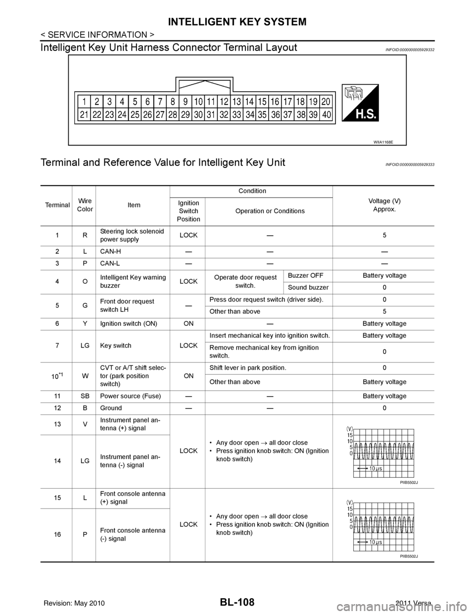
BL-108
< SERVICE INFORMATION >
INTELLIGENT KEY SYSTEM
Intelligent Key Unit Harnes s Connector Terminal Layout
INFOID:0000000005929332
Terminal and Reference Value for Intelligent Key UnitINFOID:0000000005929333
WIIA1168E
Te r m i n a lWire
Color Item Condition
Voltage (V)Approx.
Ignition
Switch
Position Operation or Conditions
1R Steering lock solenoid
power supply LOCK
— 5
2 L CAN-H —— —
3 P CAN-L —— —
4O Intelligent Key warning
buzzer LOCK
Operate door request
switch. Buzzer OFF
Battery voltage
Sound buzzer 0
5G Front door request
switch LH —Press door request switch (driver side).
0
Other than above 5
6 Y Ignition switch (ON) ON —Battery voltage
7 LG Key switch LOCKInsert mechanical key into ignition switch. Battery voltage
Remove mechanical key from ignition
switch.
0
10
*1W CVT or A/T shift selec-
tor (park position
switch)
ONShift lever in park position.
0
Other than above Battery voltage
11 SB Power source (Fuse) — —Battery voltage
12 B Ground —— 0
13 V Instrument panel an-
tenna (+) signal
LOCK• Any door open
→ all door close
• Press ignition knob switch: ON (Ignition knob switch)
14 LG Instrument panel an-
tenna (-) signal
15 L Front console antenna
(+) signal
LOCK• Any door open
→ all door close
• Press ignition knob switch: ON (Ignition knob switch)
16 P Front console antenna
(-) signal
PIIB5502J
PIIB5502J
Revision: May 2010
2011 Versa
Page 620 of 3787
BL-110
< SERVICE INFORMATION >
INTELLIGENT KEY SYSTEM
*1: With continuously variable transmission (CVT) or automatic transmission (A/T).
*2: With manual transmission (M/T).
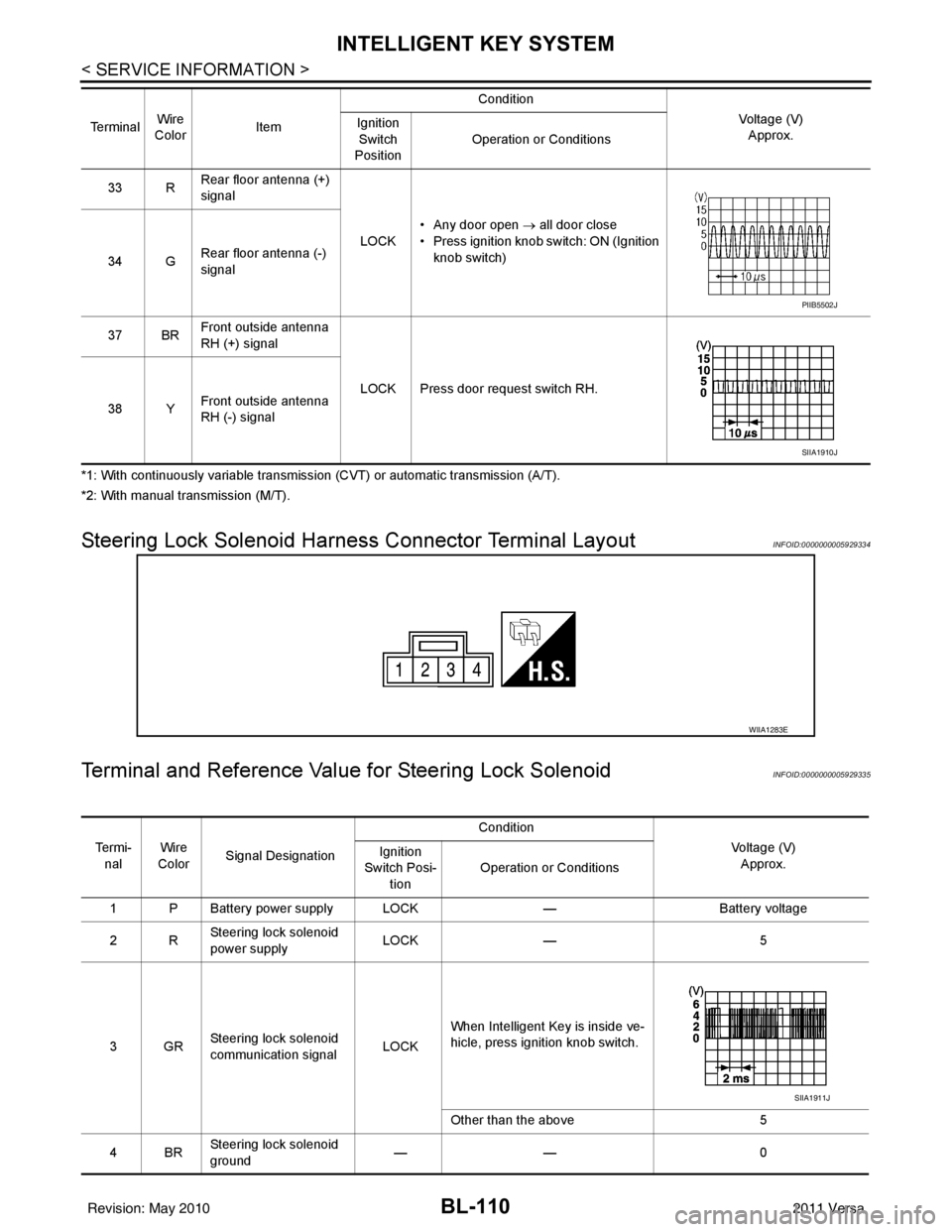
Steering Lock Solenoid Harn ess Connector Terminal LayoutINFOID:0000000005929334
Terminal and Reference Valu e for Steering Lock SolenoidINFOID:0000000005929335
33 RRear floor antenna (+)
signal
LOCK• Any door open
→ all door close
• Press ignition knob switch: ON (Ignition knob switch)
34 G Rear floor antenna (-)
signal
37 BR Front outside antenna
RH (+) signal
LOCK Press door request switch RH.
38 Y Front outside antenna
RH (-) signal
Te r m i n a l
Wire
Color Item Condition
Voltage (V)Approx.
Ignition
Switch
Position Operation or Conditions
PIIB5502J
SIIA1910J
WIIA1283E
Te r m i -
nal Wire
Color Signal Designation Condition
Voltage (V)Approx.
Ignition
Switch Posi- tion Operation or Conditions
1 P Battery power supply LOCK —Battery voltage
2R Steering lock solenoid
power supply LOCK
— 5
3GR Steering lock solenoid
communication signal
LOCKWhen Intelligent Key is inside ve-
hicle, press ignition knob switch.
Other than the above
5
4BR Steering lock solenoid
ground ——
0
SIIA1911J
Revision: May 2010 2011 Versa