display NISSAN TIIDA 2011 Service Repair Manual
[x] Cancel search | Manufacturer: NISSAN, Model Year: 2011, Model line: TIIDA, Model: NISSAN TIIDA 2011Pages: 3787, PDF Size: 78.35 MB
Page 3703 of 3787

STC-16
< DTC/CIRCUIT DIAGNOSIS >[EPS]
C1609 VEHICLE SPEED SIGNAL
C1609 VEHICLE SPEED SIGNAL
DescriptionINFOID:0000000005931242
EPS control unit receives the vehicle speed signal from ABS actuator and electric unit (control unit) via CAN
communication line.
DTC LogicINFOID:0000000005931243
DTC DETECTION LOGIC
DTC CONFIRMATION PROCEDURE
1.DTC REPRODUCTION PROCEDURE
With CONSULT-III
1. Turn the ignition switch OFF to ON.
2. Perform EPS control unit self-diagnosis.
Is DTC
“C1609” detected?
YES >> Proceed to diagnosis procedure. Refer to STC-16, "Diagnosis Procedure".
NO >> Inspection End.
Diagnosis ProcedureINFOID:0000000005931244
1.PERFORM ABS ACTUATOR AND ELECTRIC UNIT (CONTROL UNIT) SELF-DIAGNOSIS
With CONSULT-III
1. Turn the ignition switch OFF to ON.
2. Perform ABS actuator and electrical uni t (control unit) self-diagnosis. Refer to BRC-19, "
CONSULT-III
Function (ABS)".
Is any DTC detected?
YES >> Check the DTC. Refer to BRC-19, "CONSULT-III Function (ABS)".
NO >> GO TO 2.
2.PERFORM SELF-DIAGNOSIS
With CONSULT-III
Perform EPS control unit self-diagnosis.
Is DTC
“C1609” detected?
YES >> Replace EPS control unit. Refer to PS-10, "Removal and Installation".
NO >> Check EPS control unit pin terminals for damage or loose connection with harness connector. If
any item are damaged, repair or replace error-detected parts.
DTC Display item Malfunction detected condition Possible cause
C1609 CAN VHCL SPEED • Malfunction is detected in vehicle speed signal that
is output from ABS actuator and electric unit (con-
trol unit) via CAN communication.
• ABS actuator and electric unit (control unit) input signal error is detected. • Harness or connector
• CAN communication line
• EPS control unit
• ABS malfunction
- Vehicle speed signal error
Revision: May 2010
2011 Versa
Page 3704 of 3787

C1610 ENGINE STATUS SIGNALSTC-17
< DTC/CIRCUIT DIAGNOSIS > [EPS]
C
D
E
F
H I
J
K L
M A
B
STC
N
O P
C1610 ENGINE STATUS SIGNAL
DescriptionINFOID:0000000005931245
EPS control unit receives the engine status signal from ECM via CAN communication line.
DTC LogicINFOID:0000000005931246
DTC DETECTION LOGIC
DTC CONFIRMATION PROCEDURE
1.DTC REPRODUCTION PROCEDURE
With CONSULT-III
1. Turn the ignition switch OFF to ON.
2. Perform EPS control unit self-diagnosis.
Is DTC
“C1610” detected?
YES >> Proceed to diagnosis procedure. Refer to STC-17, "Diagnosis Procedure".
NO >> Inspection End.
Diagnosis ProcedureINFOID:0000000005931247
1.PERFORM ECM SELF-DIAGNOSIS
With CONSULT-III
1. Turn the ignition switch OFF to ON.
2. Perform ECM self-diagnosis. Refer to EC-106, "
CONSULT-III Function" (HR16DE), EC-612, "CONSULT-
III Function (ENGINE)" (MR18DE).
Is any DTC detected?
YES >> Check the DTC. Refer to EC-478, "DTCIndex" (HR16DE), EC-504, "U0101-U1001" (MR18DE).
NO >> GO TO 2.
2.PERFORM SELF-DIAGNOSIS
With CONSULT-III
Perform EPS control unit self-diagnosis.
Is DTC
“C1610” detected?
YES >> Replace EPS control unit. Refer to PS-10, "Removal and Installation".
NO >> Check EPS control unit pin terminals for damage or loose connection with harness connector. If
any item are damaged, repair or replace error-detected parts.
DTC Display item Malfunction detected condition Possible cause
C1610 CAN ENG RPM • Malfunction is detected in engine status signal
that is output from ECM via CAN communica-
tion.
• ECM input signal error is detected. • Harness or connector
• CAN communication line
• EPS control unit
•ECM
- Engine status signal error
Revision: May 2010
2011 Versa
Page 3705 of 3787

STC-18
< DTC/CIRCUIT DIAGNOSIS >[EPS]
U1000 CAN COMM CIRCUIT
U1000 CAN COMM CIRCUIT
DescriptionINFOID:0000000005931248
CAN (Controller Area Network) is a serial communication line for real time application. It is an on-vehicle mul-
tiplex communication line with high data communication s
peed and excellent error detection ability. Many elec-
tronic control units are equipped onto a vehicle, and each control unit shares information and links with other
control units during operation (not independent). In CA N communication, control units are connected with 2
communication lines (CAN-H line, CAN-L line) allowing a high rate of information transmission with less wiring.
Each control unit communicate data but selectively reads required data only.
DTC LogicINFOID:0000000005931249
DTC DETECTION LOGIC
DTC CONFIRMATION PROCEDURE
1.DTC REPRODUCTION PROCEDURE
With CONSULT-III
1. Turn the ignition switch OFF to ON.
2. Perform EPS control unit self-diagnosis.
Is DTC
“U1000” detected?
YES >> Proceed to diagnosis procedure. Refer to STC-18, "Diagnosis Procedure".
NO >> Inspection End
Diagnosis ProcedureINFOID:0000000005931250
1.PERFORM SELF-DIAGNOSIS
With CONSULT-III
Perform EPS control unit self-diagnosis.
Is DTC
“U1000” detected?
YES >> CAN specification chart. Refer to LAN-17, "Trouble Diagnosis Flow Chart".
NO >> Inspection End.
DTC Display item Malfunction detected condition Possible cause
U1000 CAN COMM CIRCUIT EPS control unit is not transmitting/re-
ceiving CAN communication signal for 2
seconds or more.• CAN communication error
• EPS control unit
Revision: May 2010
2011 Versa
Page 3707 of 3787

STC-20
< ECU DIAGNOSIS INFORMATION >[EPS]
EPS CONTROL UNIT
ECU DIAGNOSIS INFORMATION
EPS CONTROL UNIT
Reference ValueINFOID:0000000005931254
VALUES ON THE DIAGNOSIS TOOL
CAUTION:
The output signal indicates the EPS control unit calculation data. Th
e normal values will be displayed
even in the event that the output circuit (harness) is open.
*1: Almost in accordance with the value of MOTOR SIG. It is not a malfunction though these values are not accorded when steerin g
quickly.
*2: It is not a malfunction, though it might not be corresponding just after ignition switch in turned ON.
TERMINAL LAYOUT
PHYSICAL VALUES
Monitor item Display content Data monitor
Condition Display value
MOTOR VOL Power supply voltage for
EPS control unit Ignition switch: ON
Battery voltage
TORQUE SENSOR Steering wheel turning
force Engine runningSteering wheel: Not steering
(There is no steering force)
Approx. 0 Nm
Steering wheel: Right turn Positive value (Nm)
Steering wheel: Left turn Negative value (Nm)
MOTOR CURRENT Consumption current of
EPS motor Engine runningSteering wheel: Not steering
(There is no steering force)
Approx. 0 A
Steering wheel: Right or left
turn Displays consumption cur-
rent of EPS motor (A)
*1
MOTOR SIG
Command current to
EPS motor Engine runningSteering wheel: Not steering
(There is no steering force)
Approx. 0 A
Steering wheel: Right turn Negative value (A)
Steering wheel: Left turn Positive value (A)
DERATING STAT Displays overload sta-
tus.
Engine running
Off
VEHICLE SPEED Vehicle speed Vehicle stopped
0 km/h (0 mph)
While driving Approximately equal to the
indication on speedometer
(inside of
±10%)
*2
WARNING LAMP EPS warning lamp con-
dition EPS warning lamp: ON
On
EPS warning lamp: OFF Off
ENGINE STATUS Engine status Engine not running
Stop
Engine running Run
SGIA1624E
Revision: May 2010 2011 Versa
Page 3714 of 3787

STEERING WHEEL TURNING FORCE IS HEAVY OR LIGHTSTC-27
< SYMPTOM DIAGNOSIS > [EPS]
C
D
E
F
H I
J
K L
M A
B
STC
N
O P
STEERING WHEEL TURNING FO RCE IS HEAVY OR LIGHT
DescriptionINFOID:0000000005931263
Steering wheel turning force is heavy or light.
Diagnosis ProcedureINFOID:0000000005931264
1.CHECK THE ILLUMINATION OF THE EPS WARNING LAMP
Check that the EPS warning lamp turns ON when igni tion switch turns ON. Then, EPS warning lamp turns
OFF after the engine is started.
Is the inspection result normal?
YES >> GO TO 4.
NO >> GO TO 2.
2.PERFORM SELF-DIAGNOSIS
With CONSULT-III
1. Turn the ignition switch OFF to ON.
2. Perform EPS control unit self-diagnosis.
Is any DTC detected?
YES >> Check the DTC. Refer to STC-24, "DTC Index".
NO >> GO TO 3.
3.CHECK EPS CONTROL UNIT SIGNAL
With CONSULT-III
1. Start the engine. CAUTION:
Stop the vehicle.
2. Turn steering wheel from full left stop to full right stop.
3. Select “TORQUE SENSOR” of “DATA MONITOR” for EPS control unit.
Is the inspection result normal?
YES >> GO TO 5.
NO >> GO TO 4.
4.CHECK EPS MOTOR
Perform the trouble diagnosis of EPS motor. Refer to STC-13, "
Diagnosis Procedure".
Is the inspection result normal?
YES >> GO TO 5.
NO >> Repair or replace the specific malfunctioning part.
5.CHECK STEERING WH EEL TURNING FORCE
Check the steering wheel turning force. Refer to PS-6, "
On-Vehicle Inspection and Service".
Is the inspection result normal?
YES >> Inspection End
NO >> Check the steering wheel turning force for mechanical malfunction. Refer to PS-6, "
On-Vehicle
Inspection and Service".
Monitor item ConditionDisplay value
TORQUE SENSOR Steering wheel: Not steer-
ing (There is no steering
force)
Approx. 0 Nm
Steering wheel: Right turn Positive value (Nm)
Steering wheel: Left turn Negative value (Nm)
Revision: May 2010 2011 Versa
Page 3715 of 3787

STC-28
< SYMPTOM DIAGNOSIS >[EPS]
UNBALANCE STEERING WHEEL TURNING FORCE AND RETURN BETWEEN
RIGHT AND LEFT
UNBALANCE STEERING WHEEL TU RNING FORCE AND RETURN BE-
TWEEN RIGHT AND LEFT
DescriptionINFOID:0000000005931265
Unbalance steering wheel turning force and return between right and left.
Diagnosis ProcedureINFOID:0000000005931266
1.CHECK THE ILLUMINATION OF THE EPS WARNING LAMP
Check that the EPS warning lamp turns ON when igni tion switch turns ON. Then, EPS warning lamp turns
OFF after the engine is started.
Is the inspection result normal?
YES >> GO TO 2.
NO >> Refer to STC-26, "
Diagnosis Procedure".
2.CHECK WHEEL ALIGNMENT
1. Check the wheel alignment. Refer to FSU-7, "
On-Vehicle Inspection and Service".
2. Perform EPS control unit self-diagnosis.
Is the inspection result normal?
YES >> GO TO 3.
NO >> Adjustment of wheel alignment.
3.CHECK EPS CONTROL UNIT SIGNAL
With CONSULT-III
1. Start the engine. CAUTION:
Stop the vehicle.
2. Turn steering wheel from full left stop to full right stop.
3. Select “TORQUE SENSOR” of “DATA MONITOR” for EPS control unit.
Is the inspection result normal?
YES >> GO TO 5.
NO >> GO TO 4.
4.CHECK EPS MOTOR
Perform the trouble diagnosis of EPS motor. Refer to STC-13, "
Diagnosis Procedure".
Is the inspection result normal?
YES >> GO TO 5.
NO >> Repair or replace the specific malfunctioning part.
5.CHECK STEERING WHEEL TURNING FORCE
Check the steering wheel turning force. Refer to PS-6, "
On-Vehicle Inspection and Service".
Is the inspection result normal?
YES >> Inspection End.
NO >> Check the steering wheel turning force for mechanical malfunction. Refer to PS-6, "
On-Vehicle
Inspection and Service".
Monitor item ConditionDisplay value
TORQUE SENSOR Steering wheel: Not steer-
ing (There is no steering
force)
Approx. 0 Nm
Steering wheel: Right turn Positive value (Nm)
Steering wheel: Left turn Negative value (Nm)
Revision: May 2010 2011 Versa
Page 3716 of 3787

UNBALANCE STEERING WHEEL TURNING FORCE (TORQUE VARIATION)
STC-29
< SYMPTOM DIAGNOSIS > [EPS]
C
D
E
F
H I
J
K L
M A
B
STC
N
O P
UNBALANCE STEERING WHEEL TU RNING FORCE (TORQUE VARIA-
TION)
DescriptionINFOID:0000000005931267
Unbalance steering wheel turning force (torque variation).
Diagnosis ProcedureINFOID:0000000005931268
1.CHECK THE ILLUMINATION OF THE EPS WARNING LAMP
Check that the EPS warning lamp turns ON when igni tion switch turns ON. Then, EPS warning lamp turns
OFF after the engine is started.
Is the inspection result normal?
YES >> GO TO 2.
NO >> Refer to STC-26, "
Diagnosis Procedure".
2.CHECK STEERING COLU MN AND STEERING GEAR
Check the steering column assembly and steering gear assembly.
• Steering column assembly. Refer to PS-10, "
Removal and Installation".
• Steering gear assembly. Refer to PS-15, "
Disassembly and Assembly".
Is the inspection result normal?
YES >> GO TO 3.
NO >> Repair or replace the specific malfunctioning part.
3.CHECK EPS CONTROL UNIT SIGNAL
With CONSULT-III
1. Start the engine. CAUTION:
Stop the vehicle.
2. Turn steering wheel from full left stop to full right stop.
3. Select “TORQUE SENSOR” of “DATA MONITOR” for EPS control unit.
Is the inspection result normal?
YES >> GO TO 5.
NO >> GO TO 4.
4.CHECK EPS MOTOR
Perform the trouble diagnosis of EPS motor. Refer to STC-13, "
Diagnosis Procedure".
Is the inspection result normal?
YES >> GO TO 5.
NO >> Repair or replace the specific malfunctioning part.
5.CHECK STEERING WH EEL TURNING FORCE
Check the steering wheel turning force. Refer to PS-6, "
On-Vehicle Inspection and Service".
Is the inspection result normal?
YES >> Inspection End.
NO >> Check the steering wheel turning force for mechanical malfunction. Refer to PS-6, "
On-Vehicle
Inspection and Service".
Monitor item ConditionDisplay value
TORQUE SENSOR Steering wheel: Not steer-
ing (There is no steering
force)
Approx. 0 Nm
Steering wheel: Right turn Positive value (Nm)
Steering wheel: Left turn Negative value (Nm)
Revision: May 2010 2011 Versa
Page 3732 of 3787
WT-14
< SERVICE INFORMATION >
TROUBLE DIAGNOSES
6. Inflate all tires to proper pressure. Refer to WT-28, "Tire" .
Transmitter Wake Up OperationINFOID:0000000005931106
NOTE:
This procedure must be done after replacement of a low tire pressure warning transmitter or BCM.
New replacement transmitters are provided "asleep" and must first be "woken up" using Transmitter
Activation Tool J-45295 before ID registration can be performed.
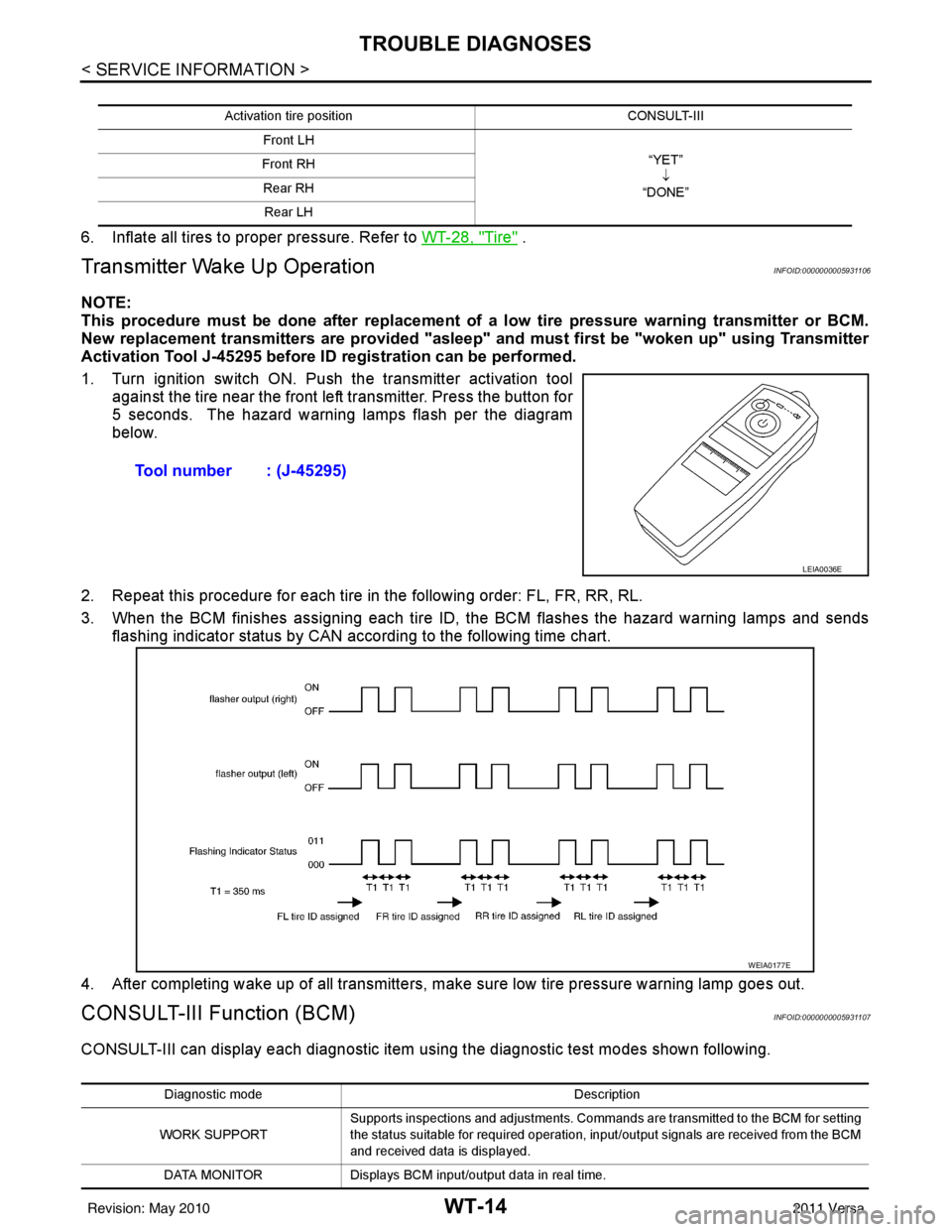
1. Turn ignition switch ON. Push the transmitter activation tool against the tire near the front left transmitter. Press the button for
5 seconds. The hazard warning lamps flash per the diagram
below.
2. Repeat this procedure for each tire in the following order: FL, FR, RR, RL.
3. When the BCM finishes assigning each tire ID, the BCM flashes the hazard warning lamps and sends flashing indicator status by CAN according to the following time chart.
4. After completing wake up of all transmitters, make sure low tire pressure warning lamp goes out.
CONSULT-III Function (BCM)INFOID:0000000005931107
CONSULT-III can display each diagnostic item us ing the diagnostic test modes shown following.
Activation tire position CONSULT-III
Front LH “YET”↓
“DONE”
Front RH
Rear RHRear LH
Tool number : (J-45295)
LEIA0036E
WEIA0177E
Diagnostic mode Description
WORK SUPPORT Supports inspections and adjustments. Commands are transmitted to the BCM for setting
the status suitable for required operation, input/output signals are received from the BCM
and received data is displayed.
DATA MONITOR Displays BCM input/output data in real time.
Revision: May 2010 2011 Versa
Page 3733 of 3787

TROUBLE DIAGNOSESWT-15
< SERVICE INFORMATION >
C
DF
G H
I
J
K L
M A
B
WT
N
O P
How to Perform Trouble Diagnosis for Quick and Accurate RepairINFOID:0000000005931108
INTRODUCTION
• Before troubleshooting, verify customer complaints.
• If a vehicle malfunction is difficult to reproduce, harnesses, harness connectors or terminals may be mal- functioning. Hold and shake these parts to make sure they are securely connected.
• When using a circuit tester to measure voltage or re sistance of each circuit, be careful not to damage or
deform connector terminals.
WORK FLOW
ACTIVE TEST Operation of electrical loads can be checked by sending drive signal to them.
SELF DIAGNOSTIC RESULT Displays BCM self-diagnosis results.
CAN DIAG SUPPORT MNTR The result of transmit/receive diagnosis of CAN communication can be read. ECU IDENTIFICATION BCM part number can be read.
CONFIGURATION Performs BCM configuration read/write functions.
Diagnostic mode
Description
Preliminary check :WT-16Self-diagnosis :WT-16Trouble diagnosis for symptoms : WT-23
SEIA0100E
Revision: May 2010 2011 Versa
Page 3735 of 3787

TROUBLE DIAGNOSESWT-17
< SERVICE INFORMATION >
C
DF
G H
I
J
K L
M A
B
WT
N
O P
Self-Diagnostic Results Mode
NOTE:
Before performing the self-diagnosis, be sure to register the ID or else the actual malfunction location may be different from
that dis-
played on CONSULT-III.
Data Monitor Mode
NOTE:
Before performing the self-diagnosis, be sure to register the ID, or the actual malfunction location may be different from that displayed on
CONSULT-III.
Self-Diagnosis (Without CONSULT-III)INFOID:0000000005931111
SELF DIAGNOSTIC PROCE DURE (WITHOUT CONSULT-III)
Diagnostic item Diagnostic item is detected when ···Reference
page
FLAT - TIRE - FL [C1704]
FLAT - TIRE - FR [C1705]
FLAT - TIRE - RR [C1706]
FLAT - TIRE - RL [C1707] Tire pressure dropped below specified value. Refer to WT-
9, "System Description".
—
[NO-DATA] - FL [C1708]
[NO-DATA] - FR [C1709]
[NO-DATA] - RR [C1710]
[NO-DATA] - RL [C1711] Data from FL transmitter cannot be received.
Data from FR transmitter cannot be received.
Data from RR transmitter cannot be received.
Data from RL transmitter cannot be received.
WT-20
[CHECKSUM- ERR] - FL [C1712]
[CHECKSUM- ERR] - FR [C1713]
[CHECKSUM- ERR] - RR [C1714]
[CHECKSUM- ERR] - RL [C1715] Checksum data from FL transmitter is malfunctioning.
Checksum data from FR transmitter is malfunctioning.
Checksum data from RR transmitter is malfunctioning.
Checksum data from RL transmitter is malfunctioning.
WT-20
[PRESSDATA- ERR] - FL [C1716]
[PRESSDATA- ERR] - FR [C1717]
[PRESSDATA- ERR] - RR [C1718]
[PRESSDATA- ERR] - RL [C1719] Air pressure data from FL transmitter is malfunctioning.
Air pressure data from FR transmitter is malfunctioning.
Air pressure data from RR transmitter is malfunctioning.
Air pressure data from RL transmitter is malfunctioning.
WT-21
[CODE- ERR] - FL [C1720]
[CODE- ERR] - FR [C1721]
[CODE- ERR] - RR [C1722]
[CODE- ERR] - RL [C1723] Function code data from FL transmitter is malfunctioning.
Function code data from FR transmitter is malfunctioning.
Function code data from RR transmitter is malfunctioning.
Function code data from RL transmitter is malfunctioning.
WT-20
[BATT - VOLT - LOW] - FL [C1724]
[BATT - VOLT - LOW] - FR [C1725]
[BATT - VOLT - LOW] - RR [C1726]
[BATT - VOLT - LOW] - RL [C1727] Battery voltage of FL transmitter drops.
Battery voltage of FR transmitter drops.
Battery voltage of RR transmitter drops.
Battery voltage of RL transmitter drops.
WT-20
VHCL_SPEED_SIG_ERR [C1729]
Vehicle speed signal is in error. WT-21
IGN_CIRCUIT_OPEN [C1735] Vehicle ignition signal is in error. WT-22
MONITORCONDITION SPECIFICATION
VEHICLE SPEED Drive vehicle. Vehicle speed (km/h or MPH)
AIR PRESS FL
AIR PRESS FR
AIR PRESS RR
AIR PRESS RL • Drive vehicle for a few minutes.
Tire pressure (kPa or psi)
or
• Ignition switch ON and activation tool is transmitting activation signals.
ID REGST FL1
ID REGST FR1
ID REGST RR1
ID REGST RL1 Ignition switch ON Registration ID: DONE
No registration ID: YET
WARNING LAMP Low tire pressure
warning lamp on: ON
Low tire pressure warning lamp off: OFF
BUZZER Buzzer in combination meter on: ON
Buzzer in combination meter off: OFF
Revision: May 2010
2011 Versa