fuel NISSAN TIIDA 2011 Service Repair Manual
[x] Cancel search | Manufacturer: NISSAN, Model Year: 2011, Model line: TIIDA, Model: NISSAN TIIDA 2011Pages: 3787, PDF Size: 78.35 MB
Page 3556 of 3787

PRECAUTIONSRSU-3
< SERVICE INFORMATION >
C
DF
G H
I
J
K L
M A
B
RSU
N
O P
5. When the repair work is completed, return the ignition switch to the ″LOCK ″ position before connecting
the battery cables. (At this time, the steering lock mechanism will engage.)
6. Perform a self-diagnosis check of al l control units using CONSULT-III.
Precaution for Rear SuspensionINFOID:0000000005931081
• When installing the rubber bushings, the final tightening must be done under unladen condition and with the
tires on level ground. Oil will shorten the life of the rubber bushings, so wipe off any spilled oil immediately.
• Unladen condition means the fuel tank, engine coolant and lubricants are at the full specification. The spare
tire, jack, hand tools, and mats are in their designated positions.
• After installing suspension components, check the wheel alignment.
• Caulking nuts are not reusable. Always use new caulking nuts for installation. New caulking nuts are pre- oiled, do not apply any additional lubrication.
Revision: May 2010 2011 Versa
Page 3559 of 3787
RSU-6
< SERVICE INFORMATION >
REAR SUSPENSION ASSEMBLY
REAR SUSPENSION ASSEMBLY
On-Vehicle Inspection and ServiceINFOID:0000000005931084
Make sure the mounting conditions (looseness, backlash) of each component and component conditions
(wear, damage) are within specifications.
SHOCK ABSORBER INSPECTION
Check shock absorber for oil leakage, damage and replace it if necessary.
Wheel AlignmentInspectionINFOID:0000000005931085
DESCRIPTION
Measure wheel alignment under unladen conditions.
NOTE:
“Unladen conditions” means that fuel, engine coolant, and lubricant are full. Spare tire, jack, hand tools and
mats are in designated positions.
PRELIMINARY
Check the following:
1. Tires for improper air pressure and wear.
2. Road wheels for runout. Refer to WT-6
.
3. Wheel bearing axial end play. Refer to RAX-6, "
On-Vehicle Inspection and Service" .
4. Shock absorber operation.
5. Each mounting part of suspension for looseness and deformation.
6. Rear suspension beam for cracks, deformation, and other damage.
7. Vehicle height (posture).
GENERAL INFORMATION AND RECOMMENDATIONS
1. A Four-Wheel Thrust Alignment should be performed. • This type of alignment is recommended for any NISSAN vehicle.
• The four-wheel “thrust” process helps ensure that the vehicle is properly aligned and the steering wheel
is centered.
• The alignment machine itself should be ca pable of accepting any NISSAN vehicle.
• The alignment machine should be checked to ensure that it is level.
2. Make sure the alignment machine is properly calibrated. • Your alignment machine should be regularly calibrated in order to give correct information.
• Check with the manufacturer of your specific al ignment machine for their recommended Service/Cali-
bration Schedule.
THE ALIGNMENT PROCESS
IMPORTANT: Use only the alignment specifications listed in this Service Manual. Refer to RSU-13, "Wheel
Alignment (Unladen*)" .
1. When displaying the alignment settings, many alignment machines use “indicators”: (Green/red, plus or minus, Go/No Go). Do NOT use these indicators.
• The alignment specifications programmed into your alignment machine that operate these indicators may not be correct.
• This may result in an ERROR.
2. Some newer alignment machines are equipped with an optional “Rolling Compensation” method to “com- pensate” the sensors (alignment targets or head units). Do NOT use this “Rolling Compensation”
method.
• Use the “Jacking Compensation” method. After inst alling the alignment targets or head units, raise the
vehicle and rotate the wheels 1/2 turn both ways.
• See Instructions in the alignment machine you are using for more information.
CAMBER INSPECTION
Revision: May 2010 2011 Versa
Page 3566 of 3787
SERVICE DATA AND SPECIFICATIONS (SDS)RSU-13
< SERVICE INFORMATION >
C
DF
G H
I
J
K L
M A
B
RSU
N
O P
SERVICE DATA AND SPECIFICATIONS (SDS)
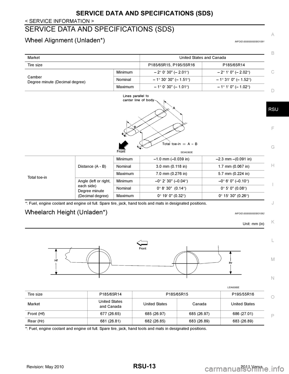
Wheel Alignment (Unladen*)INFOID:0000000005931091
*: Fuel, engine coolant and engine oil full. Spare tire, jack, hand tools and mats in designated positions.
Wheelarch Height (Unladen*)INFOID:0000000005931092
Unit: mm (in)
*: Fuel, engine coolant and engine oil full. Spare tire, jack, hand tools and mats in designated positions. Market
United States and Canada
Tire size P185/65R15, P195/55R16 P185/65R14
Camber
Degree minute (Decimal degree) Minimum – 2°
0′ 30" (– 2.01 °)– 2 ° 1 ′ 0" (– 2.02 °)
Nominal – 1 ° 30 ′ 30" (– 1.51 °)– 1° 31 ′ 0" (– 1.52 °)
Maximum – 1° 0′ 30" (– 1.01 °)– 1° 1 ′ 0" (– 1.02 °)
To t a l t o e - i n Distance (A - B)
Minimum
–1.0 mm (–0.039 in) –2.3 mm –(0.091 in)
Nominal 3.0 mm (0.118 in) 1.7 mm (0.067 in)
Maximum 7.0 mm (0.276 in) 5.7 mm (0.224 in)
Angle (left or right,
each side)
Degree minute
(Decimal degree) Minimum
–0° 2 ′ 30" (–0.04 °)– 0° 6 ′ 0" (–0.10 °)
Nominal 0° 8 ′ 30" (0.14 °)0 ° 5 ′ 0" (0.08 °)
Maximum 0° 19 ′ 0" (0.32 °)0 ° 15 ′ 30" (0.26 °)
SEIA0363E
Tire size P185/65R14P185/65R15P195/55R16
Market United States
and Canada United States
CanadaUnited States
Front (Hf) 677 (26.65)685 (26.97)685 (26.97)686 (27.01)
Rear (Hr) 681 (26.81)682 (26.85)683 (26.89)683 (26.89)
LEIA0085E
Revision: May 2010 2011 Versa
Page 3595 of 3787
STARTING SYSTEMSC-17
< SERVICE INFORMATION >
C
DE
F
G H
I
J
L
M A
B
SC
N
O P
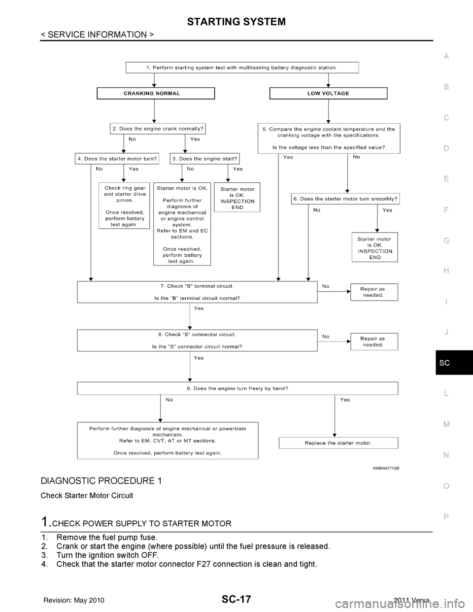
DIAGNOSTIC PROCEDURE 1
Check Starter Motor Circuit
1.CHECK POWER SUPPLY TO STARTER MOTOR
1. Remove the fuel pump fuse.
2. Crank or start the engine (where possible) until the fuel pressure is released.
3. Turn the ignition switch OFF.
4. Check that the starter motor connector F27 connection is clean and tight.
AWBIA0771GB
Revision: May 2010 2011 Versa
Page 3596 of 3787
SC-18
< SERVICE INFORMATION >
STARTING SYSTEM
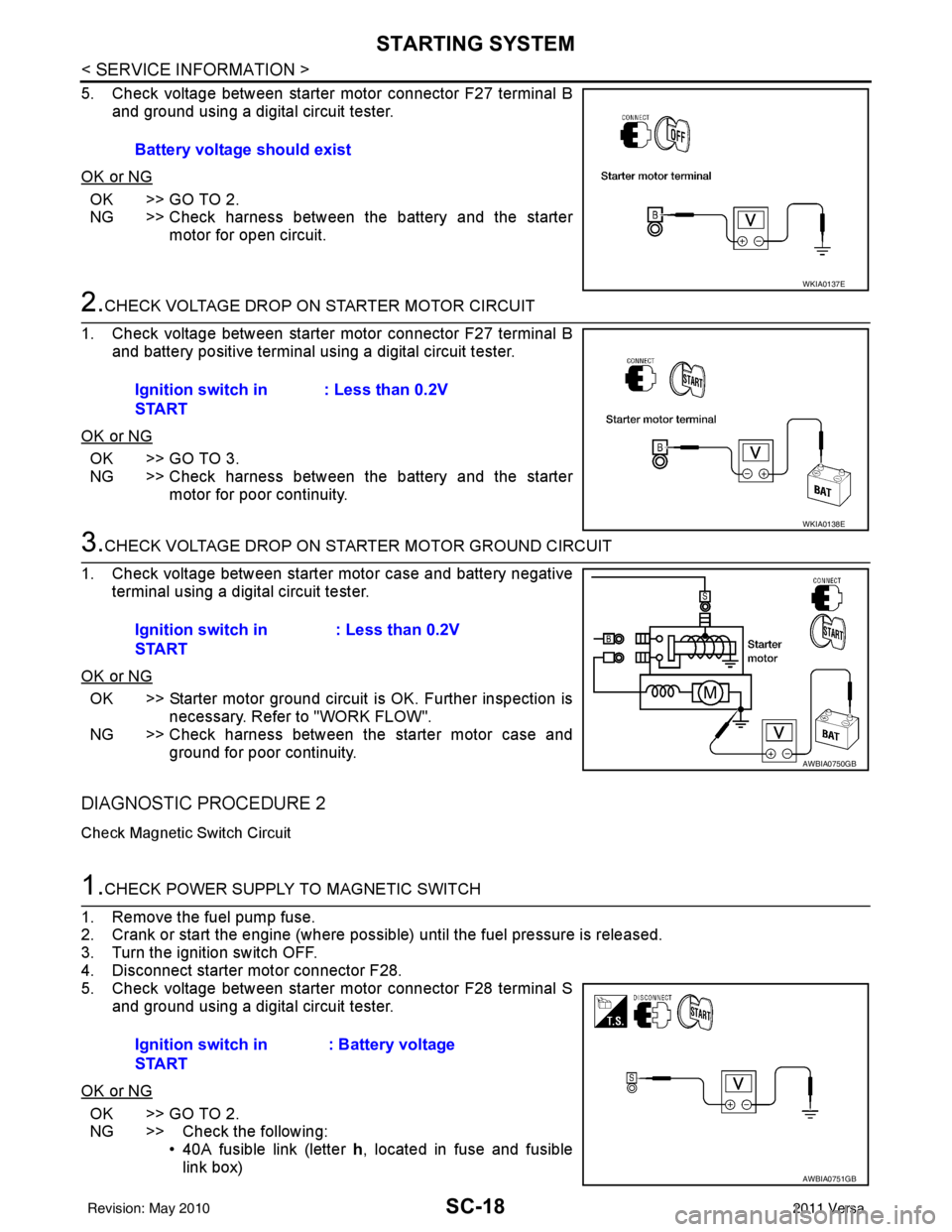
5. Check voltage between starter motor connector F27 terminal Band ground using a digital circuit tester.
OK or NG
OK >> GO TO 2.
NG >> Check harness between the battery and the starter motor for open circuit.
2.CHECK VOLTAGE DROP ON STARTER MOTOR CIRCUIT
1. Check voltage between starter motor connector F27 terminal B and battery positive terminal using a digital circuit tester.
OK or NG
OK >> GO TO 3.
NG >> Check harness between the battery and the starter motor for poor continuity.
3.CHECK VOLTAGE DROP ON STARTER MOTOR GROUND CIRCUIT
1. Check voltage between starter motor case and battery negative terminal using a digital circuit tester.
OK or NG
OK >> Starter motor ground circuit is OK. Further inspection is necessary. Refer to "WORK FLOW".
NG >> Check harness between the starter motor case and
ground for poor continuity.
DIAGNOSTIC PROCEDURE 2
Check Magnetic Switch Circuit
1.CHECK POWER SUPPLY TO MAGNETIC SWITCH
1. Remove the fuel pump fuse.
2. Crank or start the engine (where possible) until the fuel pressure is released.
3. Turn the ignition switch OFF.
4. Disconnect starter motor connector F28.
5. Check voltage between starter motor connector F28 terminal S and ground using a digital circuit tester.
OK or NG
OK >> GO TO 2.
NG >> Check the following: • 40A fusible link (letter h, located in fuse and fusible
link box)
Battery voltage should exist
WKIA0137E
Ignition switch in
START
: Less than 0.2V
WKIA0138E
Ignition switch in
START : Less than 0.2V
AWBIA0750GB
Ignition switch in
START: Battery voltage
AWBIA0751GB
Revision: May 2010
2011 Versa