engine coolant NISSAN TIIDA 2011 Service Manual PDF
[x] Cancel search | Manufacturer: NISSAN, Model Year: 2011, Model line: TIIDA, Model: NISSAN TIIDA 2011Pages: 3787, PDF Size: 78.35 MB
Page 1351 of 3787
ELECTRIC IGNITION SYSTEMEC-57
< FUNCTION DIAGNOSIS > [HR16DE]
C
D
E
F
G H
I
J
K L
M A
EC
NP
O
The knock sensor retard system is designed only for emergencies. The basic ignition timing is programmed
within the anti-knocking zone, if recommended fuel is
used under dry conditions. The retard system does not
operate under normal driving conditions. If engine knocking occurs, the knock sensor monitors the condition.
The signal is transmitted to the ECM. The ECM retards the ignition timing to eliminate the knocking condition.
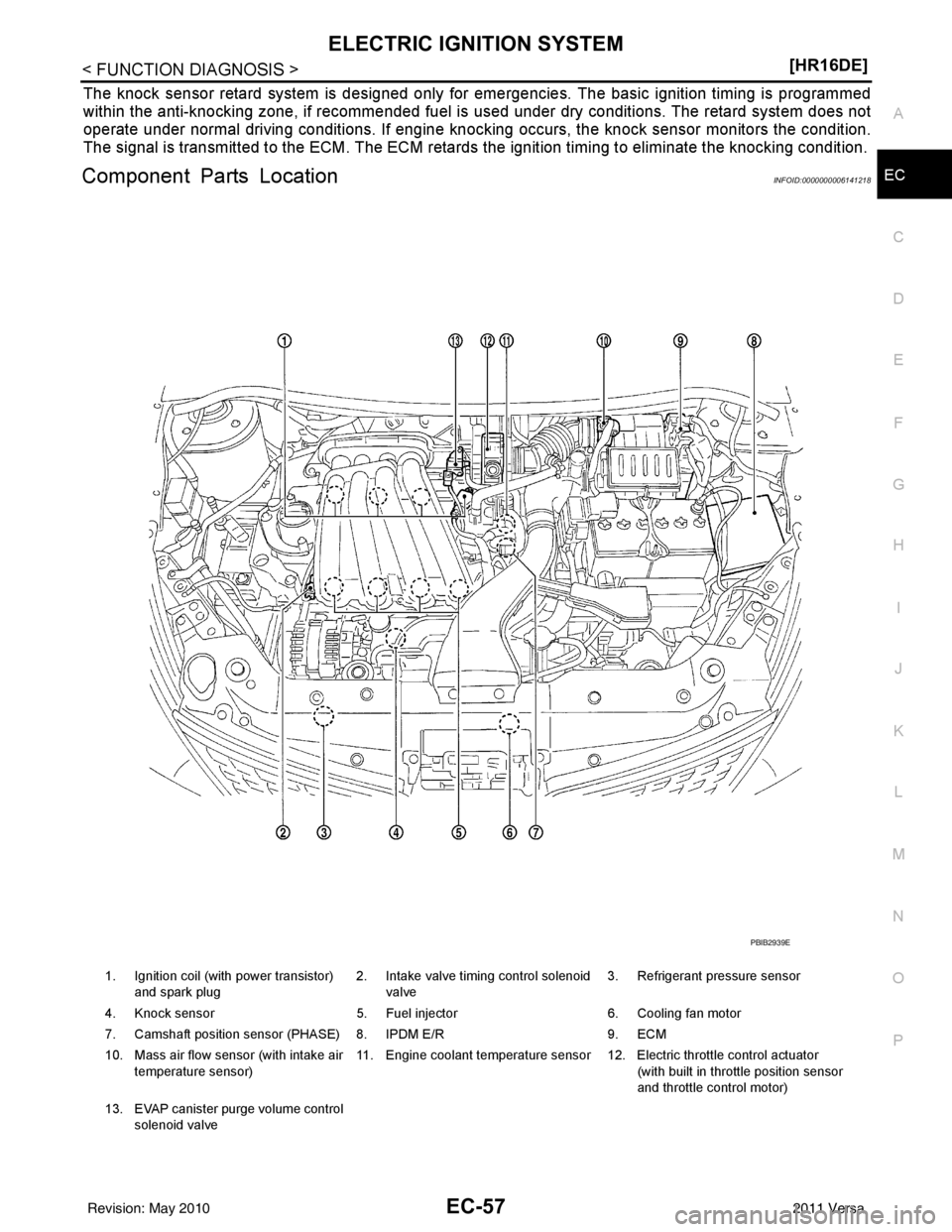
Component Parts LocationINFOID:0000000006141218
1. Ignition coil (with power transistor)
and spark plug 2. Intake valve timing control solenoid
valve 3. Refrigerant pressure sensor
4. Knock sensor 5. Fuel injector6. Cooling fan motor
7. Camshaft position sensor (PHASE) 8. IPDM E/R 9. ECM
10. Mass air flow sensor (with intake air temperature sensor) 11. Engine coolant temperature sensor 12. Electric throttle control actuator
(with built in throttle position sensor
and throttle control motor)
13. EVAP canister purge volume control solenoid valve
PBIB2939E
Revision: May 2010 2011 Versa
Page 1352 of 3787
EC-58
< FUNCTION DIAGNOSIS >[HR16DE]
ELECTRIC IGNITION SYSTEM
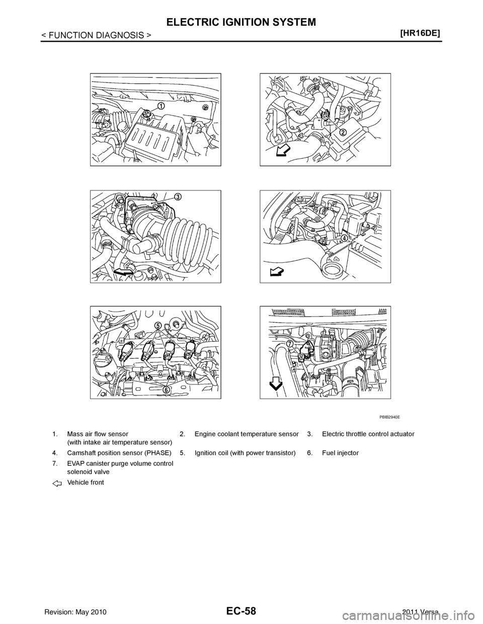
1. Mass air flow sensor
(with intake air temperature sensor) 2. Engine coolant temperature sensor 3. Electric throttle control actuator
4. Camshaft position sensor (PHASE) 5. Ignition coil (with power transistor) 6. Fuel injector
7. EVAP canister purge volume control solenoid valve
Vehicle front
PBIB2940E
Revision: May 2010 2011 Versa
Page 1355 of 3787
ELECTRIC IGNITION SYSTEMEC-61
< FUNCTION DIAGNOSIS > [HR16DE]
C
D
E
F
G H
I
J
K L
M A
EC
NP
O
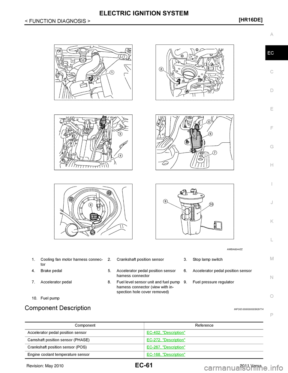
Component DescriptionINFOID:0000000005929774
1. Cooling fan motor harness connec-
tor 2. Crankshaft position sensor 3. Stop lamp switch
4. Brake pedal 5. Accelerator pedal position sensor
harness connector 6. Accelerator pedal position sensor
7. Accelerator pedal 8. Fuel level sensor unit and fuel pump
harness connector (view with in-
spection hole cover removed) 9. Fuel pressure regulator
10. Fuel pump
AWBIA0044ZZ
Component Reference
Accelerator pedal position sensor EC-402, "
Description"
Camshaft position sensor (PHASE)EC-272, "Description"
Crankshaft position sensor (POS)EC-267, "Description"
Engine coolant temperature sensorEC-168, "Description"
Revision: May 2010 2011 Versa
Page 1357 of 3787
AIR CONDITIONING CUT CONTROLEC-63
< FUNCTION DIAGNOSIS > [HR16DE]
C
D
E
F
G H
I
J
K L
M A
EC
NP
O
AIR CONDITIONING
CUT CONTROL
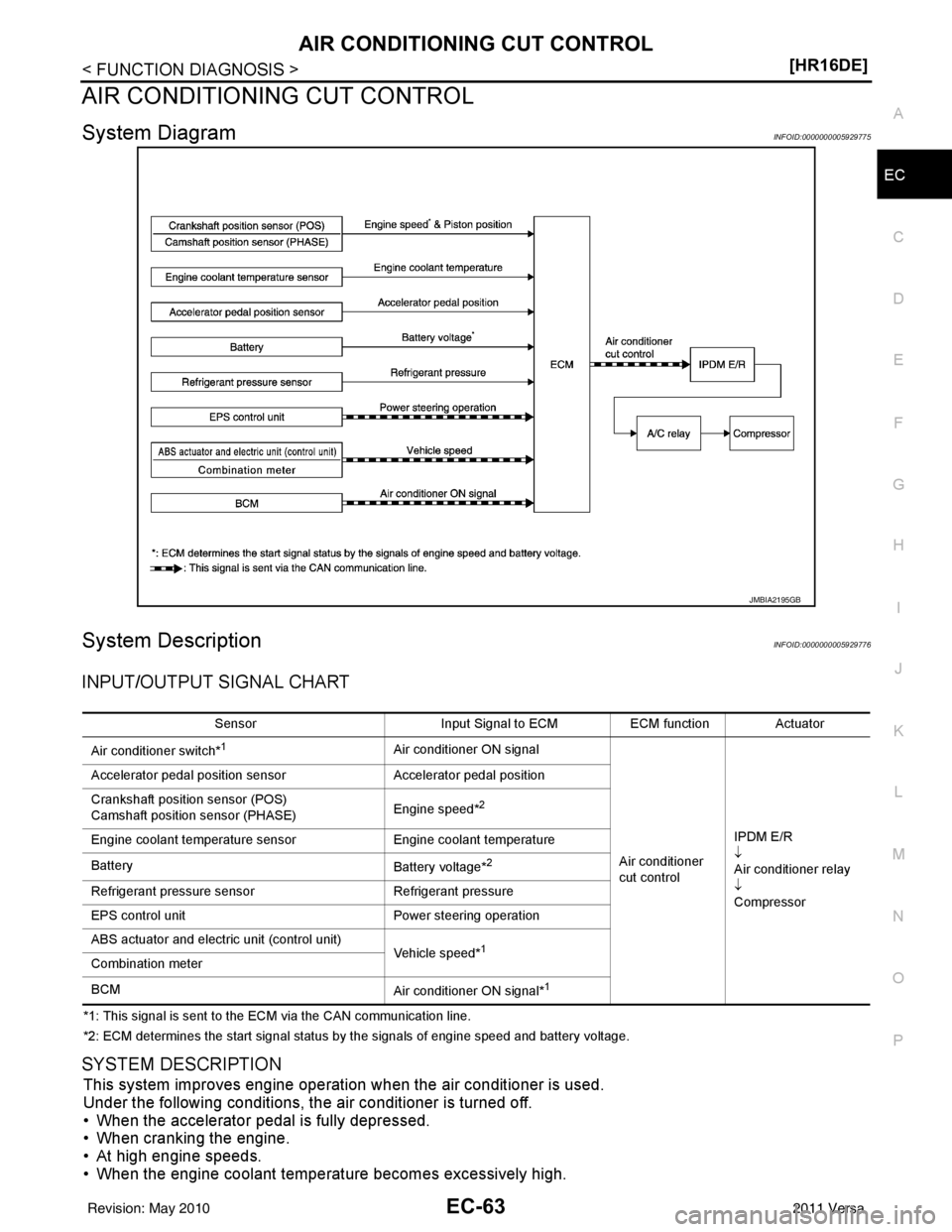
System DiagramINFOID:0000000005929775
System DescriptionINFOID:0000000005929776
INPUT/OUTPUT SIGNAL CHART
*1: This signal is sent to the ECM via the CAN communication line.
*2: ECM determines the start signal status by the signals of engine speed and battery voltage.
SYSTEM DESCRIPTION
This system improves engine operation when the air conditioner is used.
Under the following conditions, the air conditioner is turned off.
• When the accelerator pedal is fully depressed.
• When cranking the engine.
• At high engine speeds.
• When the engine coolant temperature becomes excessively high.
JMBIA2195GB
Sensor Input Signal to ECMECM functionActuator
Air conditioner switch*
1Air conditioner ON signal
Air conditioner
cut controlIPDM E/R
↓
Air conditioner relay
↓
Compressor
Accelerator pedal position sensor
Accelerator pedal position
Crankshaft position sensor (POS)
Camshaft position sensor (PHASE) Engine speed*
2
Engine coolant temperature sensor
Engine coolant temperature
Battery Battery voltage*
2
Refrigerant pressure sensorRefrigerant pressure
EPS control unit Power steering operation
ABS actuator and electric unit (control unit) Vehicle speed*
1
Combination meter
BCMAir conditioner ON signal*
1
Revision: May 2010 2011 Versa
Page 1358 of 3787
EC-64
< FUNCTION DIAGNOSIS >[HR16DE]
AIR CONDITIONING CUT CONTROL
• When operating power steering during low engine speed or low vehicle speed.
• When engine speed is excessively low.
• When refrigerant pressure is excessively low or high.
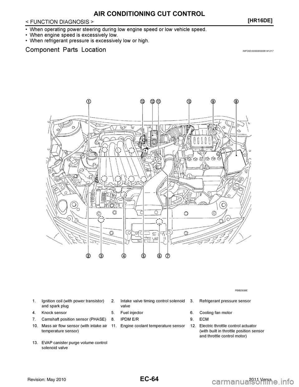
Component Parts LocationINFOID:0000000006141217
1. Ignition coil (with power transistor)
and spark plug 2. Intake valve timing control solenoid
valve 3. Refrigerant pressure sensor
4. Knock sensor 5. Fuel injector6. Cooling fan motor
7. Camshaft position sensor (PHASE) 8. IPDM E/R 9. ECM
10. Mass air flow sensor (with intake air temperature sensor) 11. Engine coolant temperature sensor 12. Electric throttle control actuator
(with built in throttle position sensor
and throttle control motor)
13. EVAP canister purge volume control solenoid valve
PBIB2939E
Revision: May 2010 2011 Versa
Page 1359 of 3787
AIR CONDITIONING CUT CONTROLEC-65
< FUNCTION DIAGNOSIS > [HR16DE]
C
D
E
F
G H
I
J
K L
M A
EC
NP
O
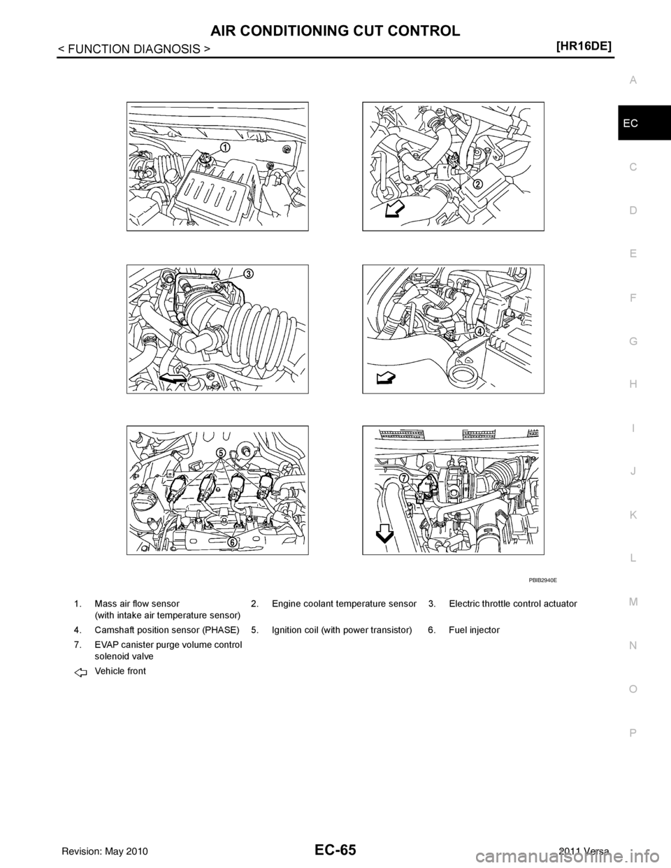
1. Mass air flow sensor
(with intake air temperature sensor) 2. Engine coolant temperature sensor 3. Electric throttle control actuator
4. Camshaft position sensor (PHASE) 5. Ignition coil (with power transistor) 6. Fuel injector
7. EVAP canister purge volume control solenoid valve
Vehicle front
PBIB2940E
Revision: May 2010 2011 Versa
Page 1363 of 3787
AIR CONDITIONING CUT CONTROLEC-69
< FUNCTION DIAGNOSIS > [HR16DE]
C
D
E
F
G H
I
J
K L
M A
EC
NP
O
Engine coolant temperature sensor
EC-168, "Description"
Refrigerant pressure sensorEC-460, "Description"
Component Reference
Revision: May 2010 2011 Versa
Page 1365 of 3787
COOLING FAN CONTROLEC-71
< FUNCTION DIAGNOSIS > [HR16DE]
C
D
E
F
G H
I
J
K L
M A
EC
NP
O
COOLING FAN CONTROL
System DiagramINFOID:0000000005929780
System DescriptionINFOID:0000000005929781
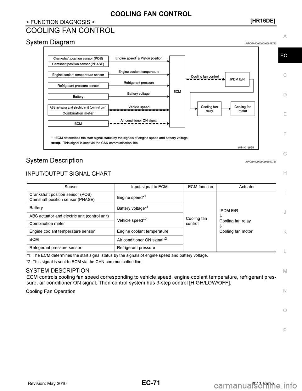
INPUT/OUTPUT SIGNAL CHART
*1: The ECM determines the start signal status by the signals of engine speed and battery voltage.
*2: This signal is sent to ECM via the CAN communication line.
SYSTEM DESCRIPTION
ECM controls cooling fan speed corresponding to vehicle speed, engine coolant temperature, refrigerant pres-
sure, air conditioner ON signal. Then control
system has 3-step control [HIGH/LOW/OFF].
Cooling Fan Operation
JMBIA2196GB
Sensor Input signal to ECM ECM function Actuator
Crankshaft position sensor (POS)
Camshaft position sensor (PHASE) Engine speed*
1
Cooling fan
controlIPDM E/R
↓
Cooling fan relay
↓
Cooling fan motor
Battery
Battery voltage*
1
ABS actuator and electric unit (control unit)
Vehicle speed*2Combination meter
Engine coolant temperature sensorEngine coolant temperature
BCM Air conditioner ON signal*
2
Refrigerant pressure sensorRefrigerant pressure
Revision: May 2010 2011 Versa
Page 1367 of 3787
COOLING FAN CONTROLEC-73
< FUNCTION DIAGNOSIS > [HR16DE]
C
D
E
F
G H
I
J
K L
M A
EC
NP
O
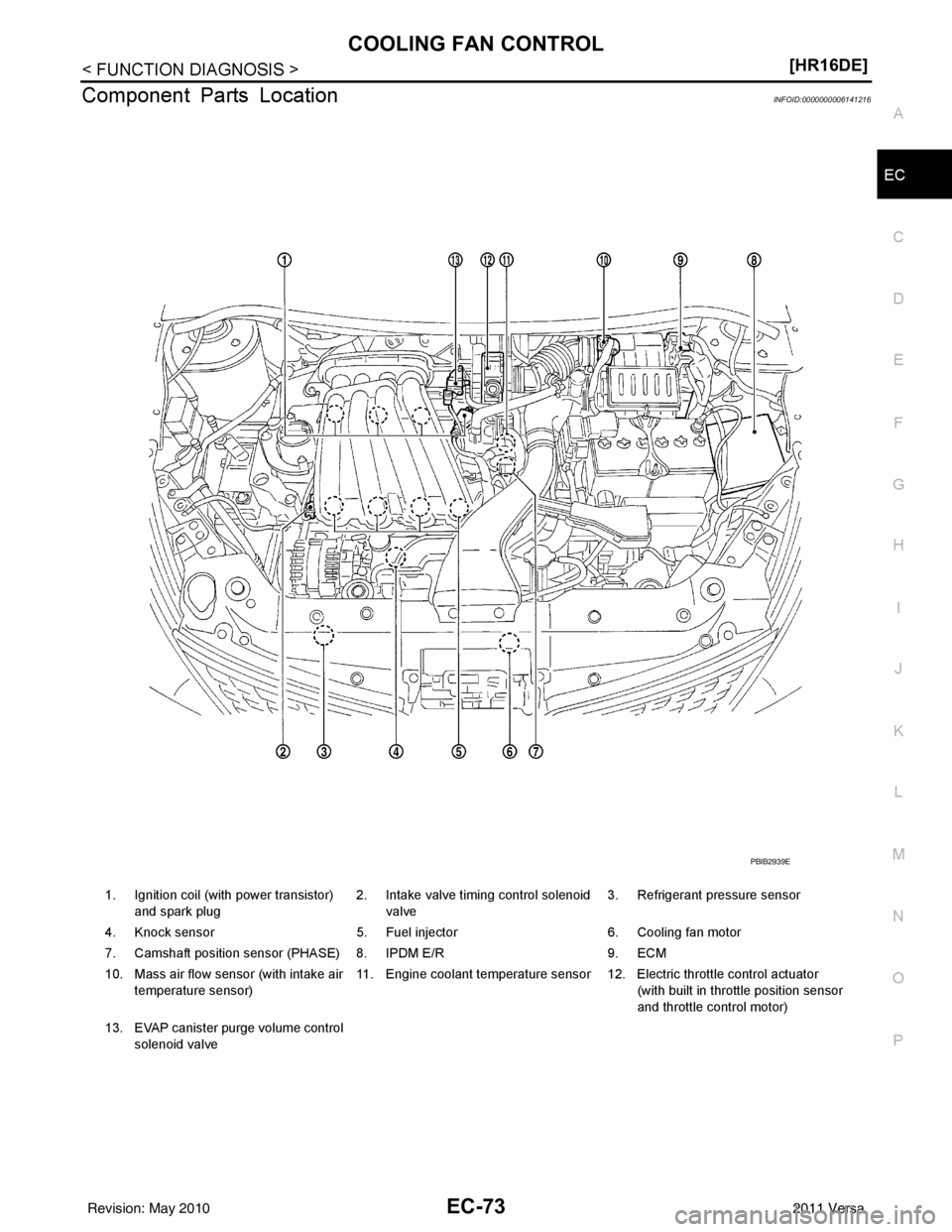
Component Parts LocationINFOID:0000000006141216
1. Ignition coil (with power transistor)
and spark plug 2. Intake valve timing control solenoid
valve 3. Refrigerant pressure sensor
4. Knock sensor 5. Fuel injector6. Cooling fan motor
7. Camshaft position sensor (PHASE) 8. IPDM E/R 9. ECM
10. Mass air flow sensor (with intake air temperature sensor) 11. Engine coolant temperature sensor 12. Electric throttle control actuator
(with built in throttle position sensor
and throttle control motor)
13. EVAP canister purge volume control solenoid valve
PBIB2939E
Revision: May 2010 2011 Versa
Page 1368 of 3787
EC-74
< FUNCTION DIAGNOSIS >[HR16DE]
COOLING FAN CONTROL
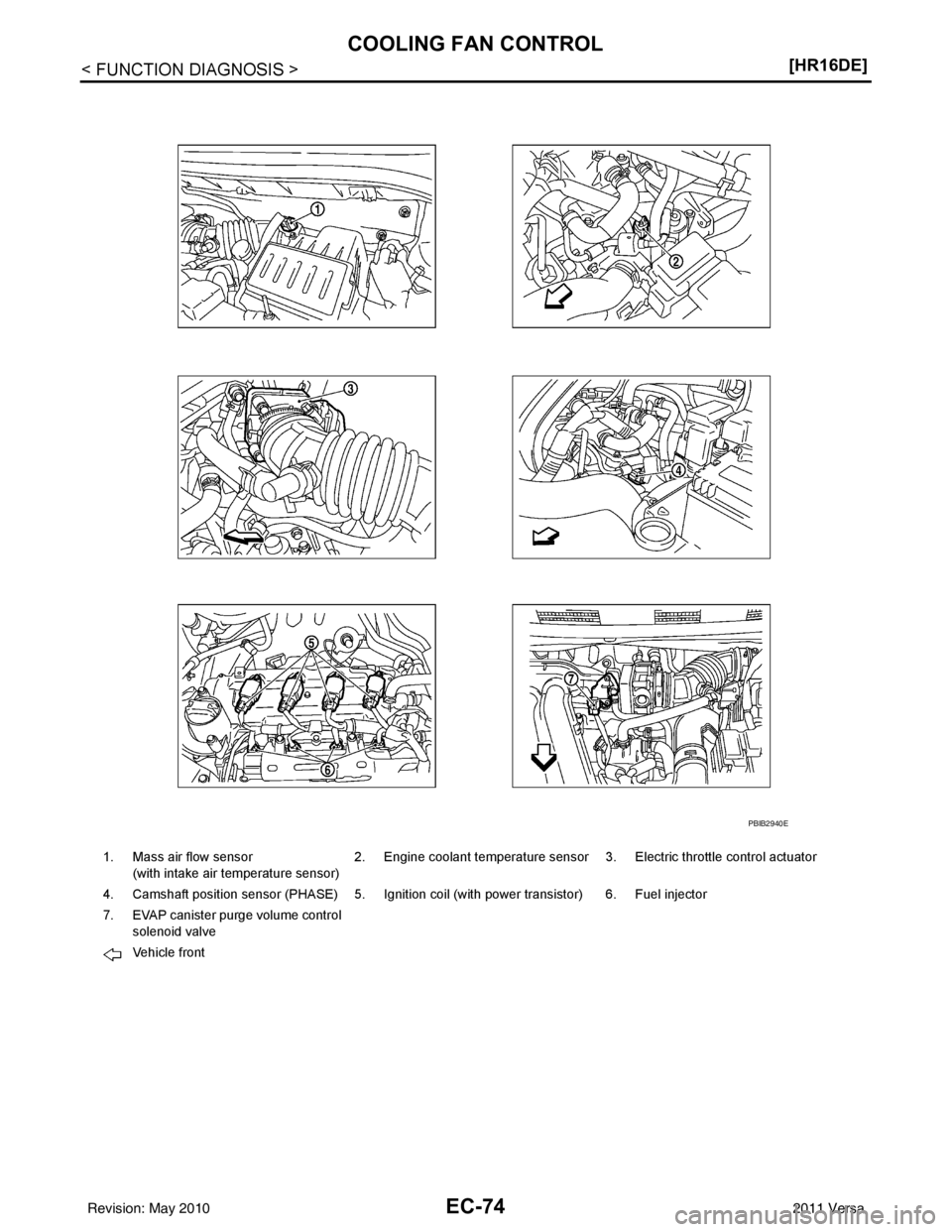
1. Mass air flow sensor
(with intake air temperature sensor) 2. Engine coolant temperature sensor 3. Electric throttle control actuator
4. Camshaft position sensor (PHASE) 5. Ignition coil (with power transistor) 6. Fuel injector
7. EVAP canister purge volume control solenoid valve
Vehicle front
PBIB2940E
Revision: May 2010 2011 Versa