ABS NISSAN TIIDA 2011 Service Repair Manual
[x] Cancel search | Manufacturer: NISSAN, Model Year: 2011, Model line: TIIDA, Model: NISSAN TIIDA 2011Pages: 3787, PDF Size: 78.35 MB
Page 9 of 3787

QUICK REFERENCE INDEX: VERSA
2011
MR18DE
TypeWith ABS or VDC/TCS/ABSWithout ABS
Front brake Brake model AD22VK
Cylinder bore diameter 53.97 mm (2.125 in)
Pad
Length × width × thickness 11 5 . 0 m m
× 41.0 mm × 9.0 mm
(4.528 in × 1.614 in × 0.354 in)
Rotor outer diameter × thickness 260 mm × 22.0 mm (10.24 in × 0.866 in)
Rear brake Brake model LT20
Cylinder bore diameter 15.87 mm (0.625 in)17.46 mm (0.687 in)
Drum inner diameter 203 mm (7.992 in)
Master cylinder Cylinder bore diameter 22.22 mm (0.875 in)
Brake booster Booster model C255
Diaphragm diameter 255 mm (10.04 in)
Recommended brake fluid DOT 3
Front brake Brake modelCLZ25VF
Cylinder bore diameter 57.2 mm (2.252 in)
Pad
Length × width × thickness 125.6 mm
× 48.0 mm × 9.5 mm
(4.945 in × 1.890 in × 0.374 in)
Rotor outer diameter × thickness 280 mm × 24.0 mm (11.02 in × 0.945 in)
Rear brake Brake model LT23
Cylinder bore diameter 19.06 mm (0.750 in)
Drum inner diameter 228.6 mm (9.000 in)
Master cylinder Cylinder bore diameter 23.81 ± 0.015 mm (0.937 ± 0.001 in)
Brake booster Booster model C255
Diaphragm diameter 255 mm (10.04 in)
Recommended brake fluid DOT 3
Page 232 of 3787
SHIFT CONTROL SYSTEMAT-215
< SERVICE INFORMATION >
DE
F
G H
I
J
K L
M A
B
AT
N
O P
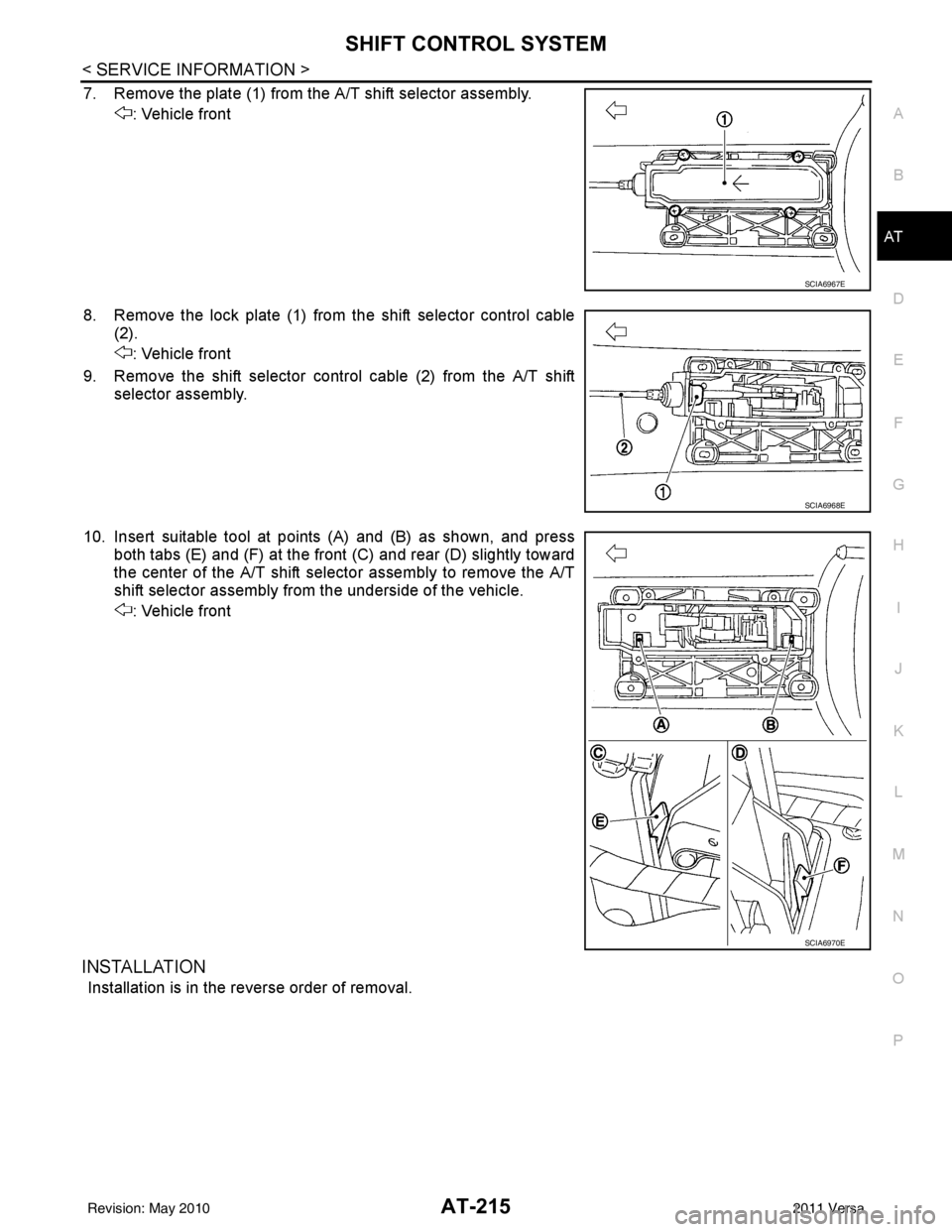
7. Remove the plate (1) from the A/T shift selector assembly. : Vehicle front
8. Remove the lock plate (1) from the shift selector control cable (2).
: Vehicle front
9. Remove the shift selector control cable (2) from the A/T shift selector assembly.
10. Insert suitable tool at points (A) and (B) as shown, and press both tabs (E) and (F) at the front (C) and rear (D) slightly toward
the center of the A/T shift select or assembly to remove the A/T
shift selector assembly from the underside of the vehicle.
: Vehicle front
INSTALLATION
Installation is in the reverse order of removal.
SCIA6967E
SCIA6968E
SCIA6970E
Revision: May 2010 2011 Versa
Page 233 of 3787
AT-216
< SERVICE INFORMATION >
SHIFT CONTROL SYSTEM
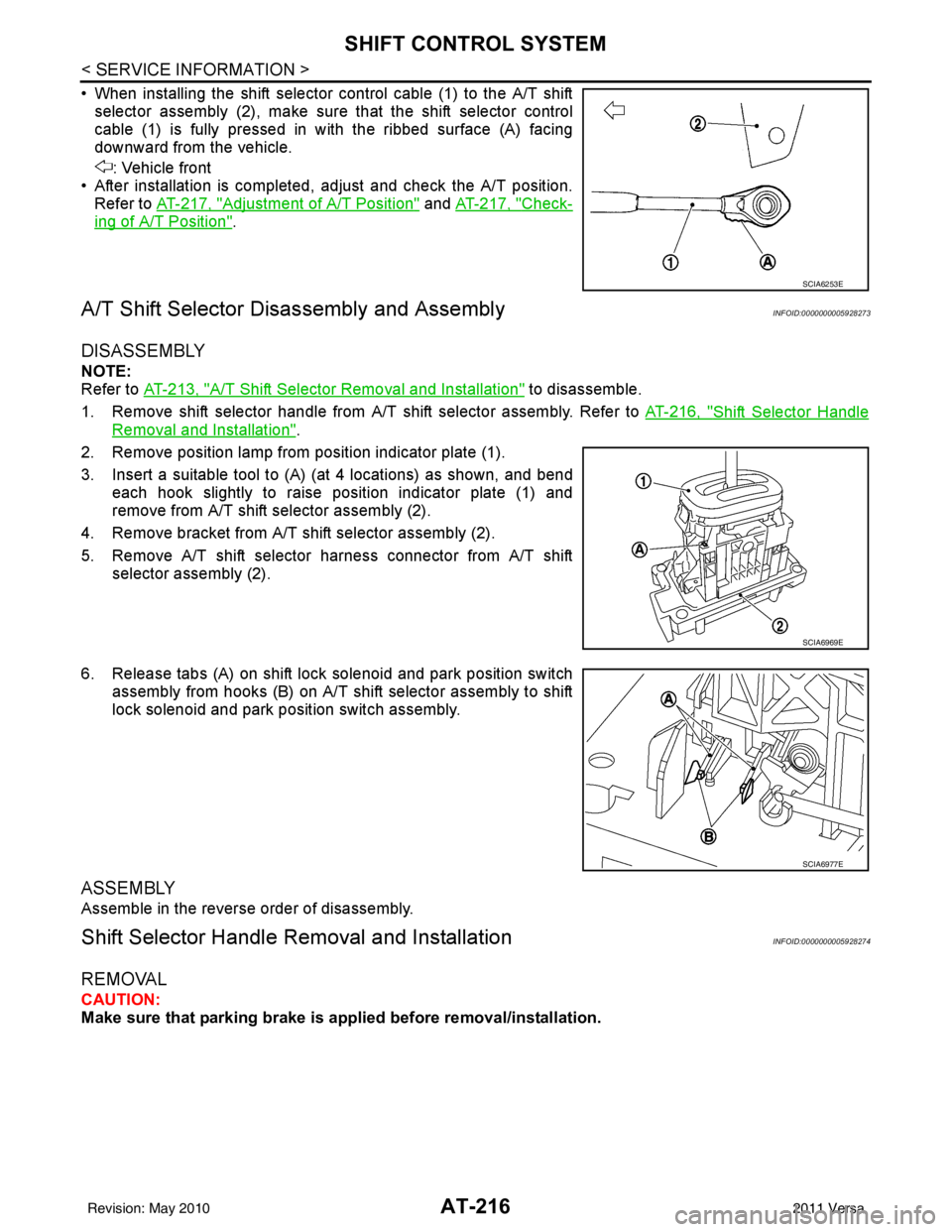
• When installing the shift selector control cable (1) to the A/T shiftselector assembly (2), make sure that the shift selector control
cable (1) is fully pressed in with the ribbed surface (A) facing
downward from the vehicle.
: Vehicle front
• After installation is completed, adjust and check the A/T position. Refer to AT-217, "
Adjustment of A/T Position" and AT-217, "Check-
ing of A/T Position".
A/T Shift Selector Di sassembly and AssemblyINFOID:0000000005928273
DISASSEMBLY
NOTE:
Refer to AT-213, "
A/T Shift Selector Removal and Installation" to disassemble.
1. Remove shift selector handle from A/T shift selector assembly. Refer to AT-216, "
Shift Selector Handle
Removal and Installation".
2. Remove position lamp from position indicator plate (1).
3. Insert a suitable tool to (A) (at 4 locations) as shown, and bend each hook slightly to raise position indicator plate (1) and
remove from A/T shift selector assembly (2).
4. Remove bracket from A/T shift selector assembly (2).
5. Remove A/T shift selector harness connector from A/T shift selector assembly (2).
6. Release tabs (A) on shift lock solenoid and park position switch assembly from hooks (B) on A/T shift selector assembly to shift
lock solenoid and park position switch assembly.
ASSEMBLY
Assemble in the reverse order of disassembly.
Shift Selector Handle Removal and InstallationINFOID:0000000005928274
REMOVAL
CAUTION:
Make sure that parking brake is applied before removal/installation.
SCIA6253E
SCIA6969E
SCIA6977E
Revision: May 2010 2011 Versa
Page 236 of 3787
KEY INTERLOCK CABLEAT-219
< SERVICE INFORMATION >
DE
F
G H
I
J
K L
M A
B
AT
N
O P
KEY INTERLOCK CABLE
Removal and InstallationINFOID:0000000005928277
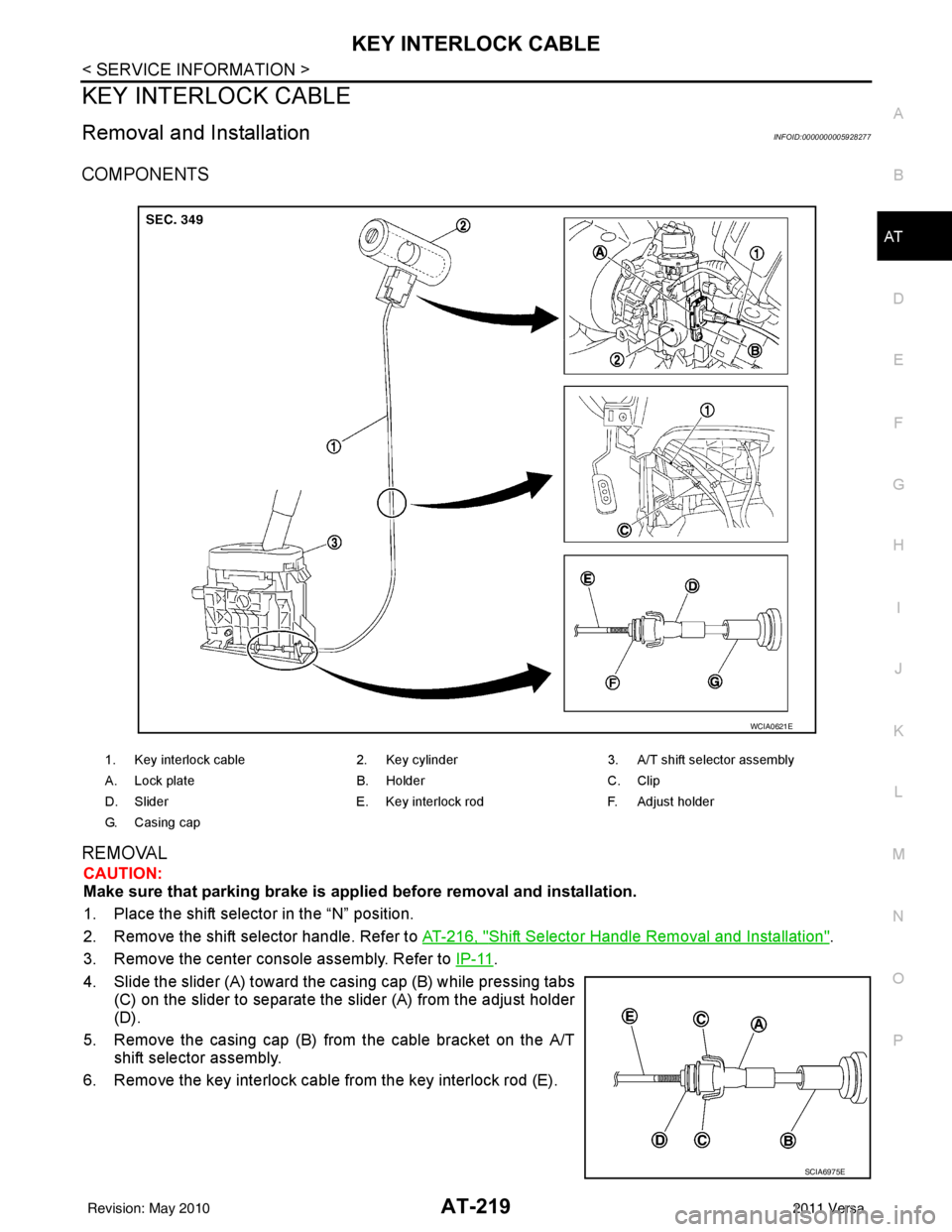
COMPONENTS
REMOVAL
CAUTION:
Make sure that parking brake is applie d before removal and installation.
1. Place the shift selector in the “N” position.
2. Remove the shift selector handle. Refer to AT-216, "
Shift Selector Handle Removal and Installation".
3. Remove the center console assembly. Refer to IP-11
.
4. Slide the slider (A) toward the casing cap (B) while pressing tabs (C) on the slider to separate the slider (A) from the adjust holder
(D).
5. Remove the casing cap (B) from the cable bracket on the A/T shift selector assembly.
6. Remove the key interlock cable from the key interlock rod (E).
1. Key interlock cable 2. Key cylinder3. A/T shift selector assembly
A. Lock plate B. HolderC. Clip
D. Slider E. Key interlock rodF. Adjust holder
G. C a s i n g c a p
WCIA0621E
SCIA6975E
Revision: May 2010 2011 Versa
Page 238 of 3787
KEY INTERLOCK CABLEAT-221
< SERVICE INFORMATION >
DE
F
G H
I
J
K L
M A
B
AT
N
O P
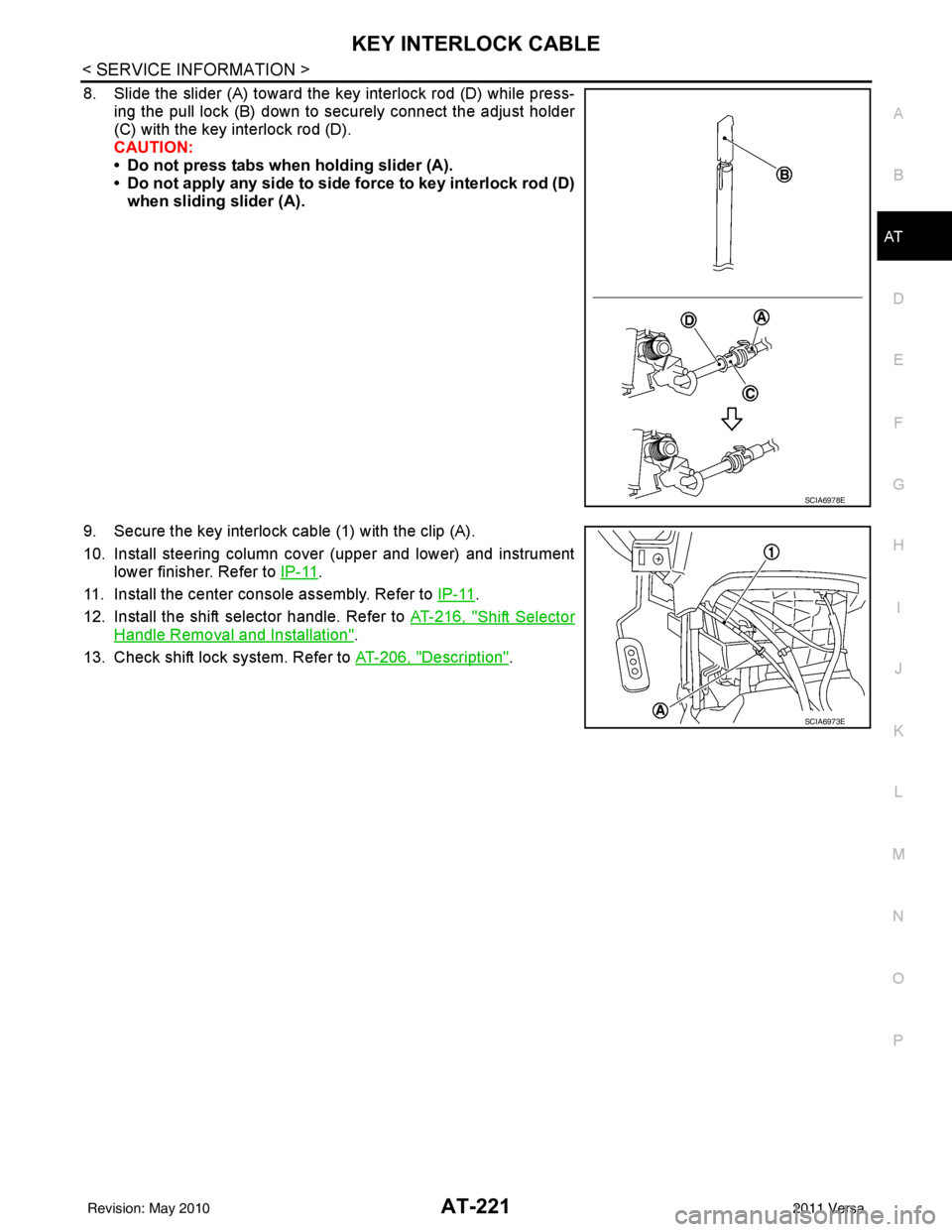
8. Slide the slider (A) toward the key interlock rod (D) while press- ing the pull lock (B) down to securely connect the adjust holder
(C) with the key interlock rod (D).
CAUTION:
• Do not press tabs when holding slider (A).
• Do not apply any side to side force to key interlock rod (D)when sliding slider (A).
9. Secure the key interlock cable (1) with the clip (A).
10. Install steering column cover (upper and lower) and instrument lower finisher. Refer to IP-11
.
11. Install the center console assembly. Refer to IP-11
.
12. Install the shift selector handle. Refer to AT-216, "
Shift Selector
Handle Removal and Installation".
13. Check shift lock system. Refer to AT-206, "
Description".
SCIA6978E
SCIA6973E
Revision: May 2010 2011 Versa
Page 254 of 3787
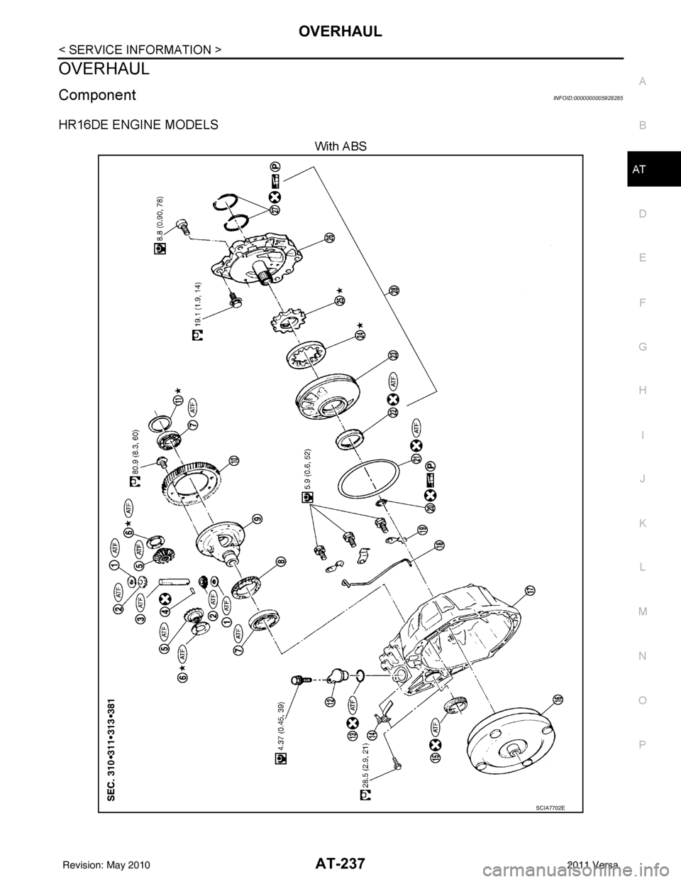
OVERHAULAT-237
< SERVICE INFORMATION >
DE
F
G H
I
J
K L
M A
B
AT
N
O P
OVERHAUL
ComponentINFOID:0000000005928285
HR16DE ENGINE MODELS
With ABS
SCIA7702E
Revision: May 2010 2011 Versa
Page 256 of 3787
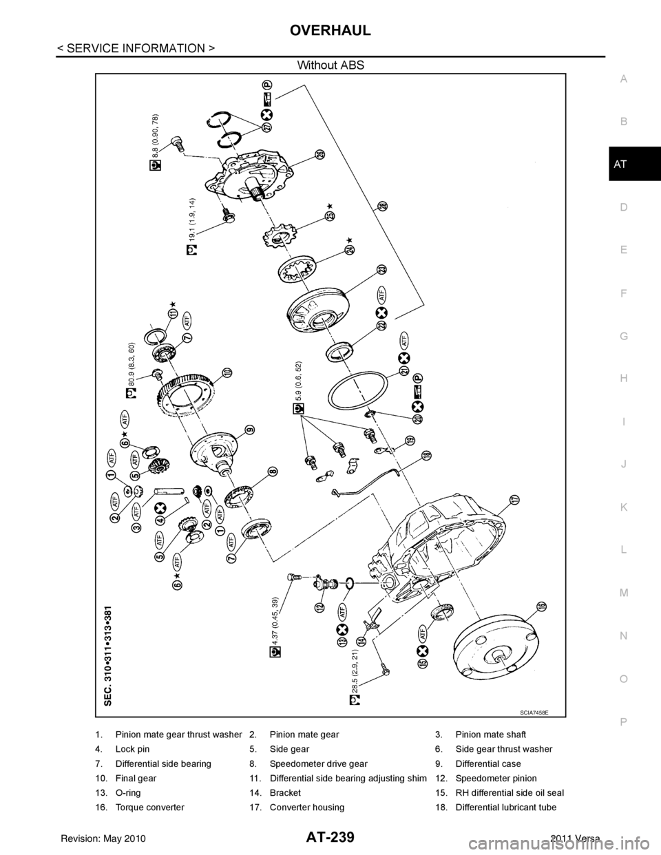
OVERHAULAT-239
< SERVICE INFORMATION >
DE
F
G H
I
J
K L
M A
B
AT
N
O P
Without ABS
SCIA7458E
1. Pinion mate gear thrust washer 2. Pinion mate gear 3. Pinion mate shaft
4. Lock pin 5. Side gear 6. Side gear thrust washer
7. Differential side bearing 8. Speedometer drive gear 9. Differential case
10. Final gear 11. Differential side bearing adjusting shim 12. Speedometer pinion
13. O-ring 14. Bracket 15. RH differential side oil seal
16. Torque converter 17. Converter housing 18. Differential lubricant tube
Revision: May 2010 2011 Versa
Page 261 of 3787
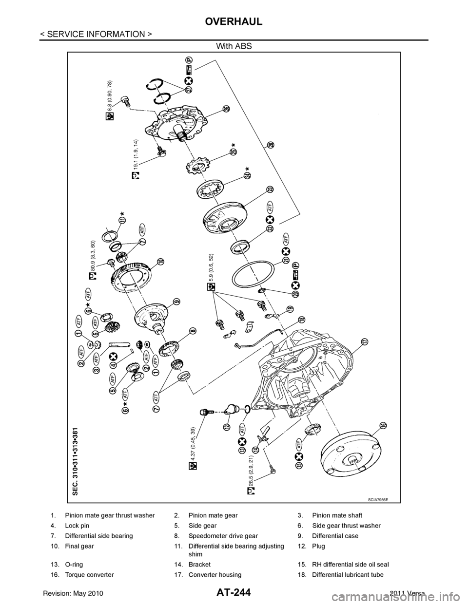
AT-244
< SERVICE INFORMATION >
OVERHAUL
With ABS
SCIA7956E
1. Pinion mate gear thrust washer 2. Pinion mate gear3. Pinion mate shaft
4. Lock pin 5. Side gear 6. Side gear thrust washer
7. Differential side bearing 8. Speedometer drive gear9. Differential case
10. Final gear 11. Differential side bearing adjusting
shim 12. Plug
13. O-ring 14. Bracket 15. RH differential side oil seal
16. Torque converter 17. Converter housing18. Differential lubricant tube
Revision: May 2010 2011 Versa
Page 262 of 3787
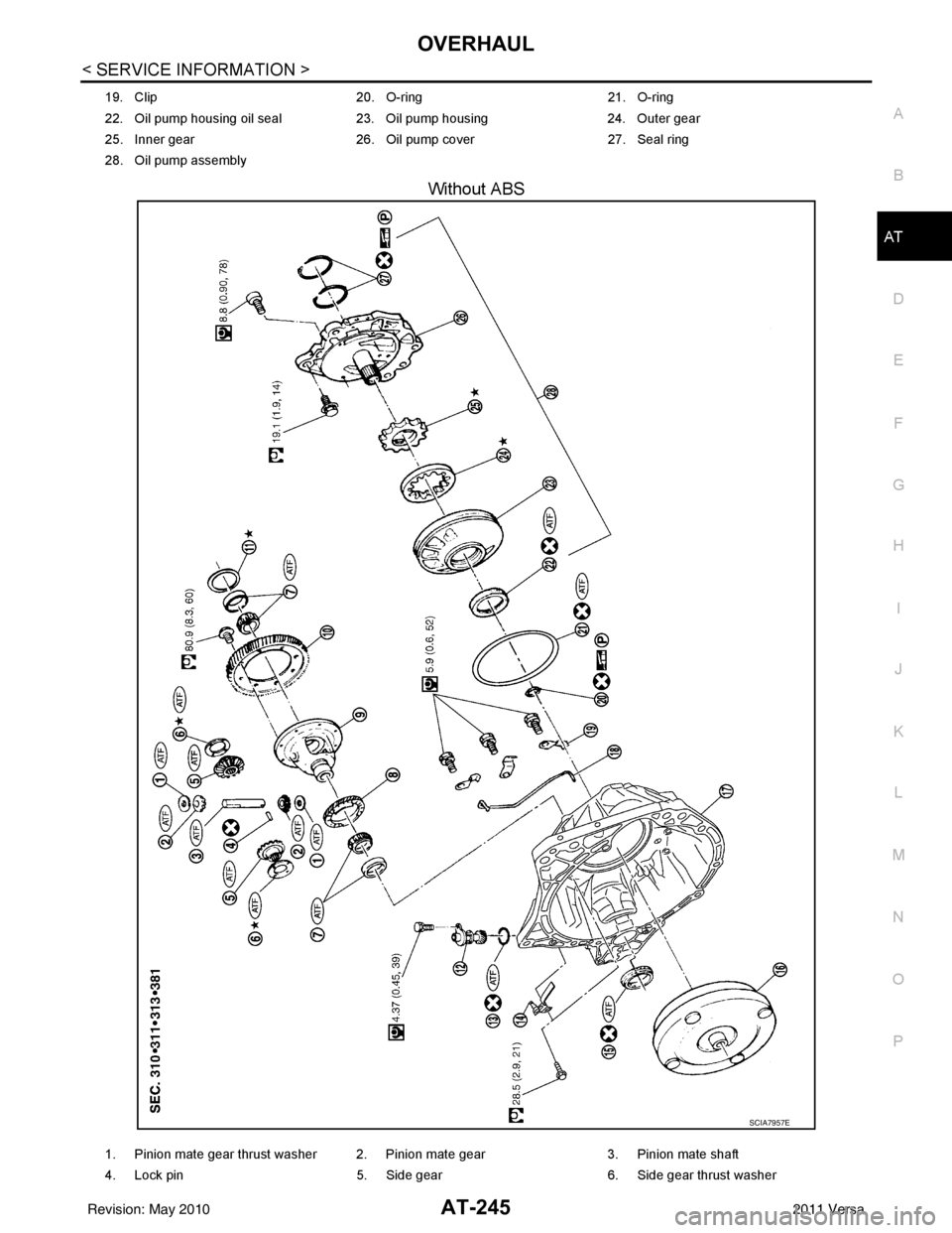
OVERHAULAT-245
< SERVICE INFORMATION >
DE
F
G H
I
J
K L
M A
B
AT
N
O P
Without ABS
19. Clip 20. O-ring21. O-ring
22. Oil pump housing oil seal 23. Oil pump housing24. Outer gear
25. Inner gear 26. Oil pump cover27. Seal ring
28. Oil pump assembly
SCIA7957E
1. Pinion mate gear thrust washer 2. Pinion mate gear 3. Pinion mate shaft
4. Lock pin 5. Side gear6. Side gear thrust washer
Revision: May 2010 2011 Versa
Page 275 of 3787
AT-258
< SERVICE INFORMATION >
DISASSEMBLY
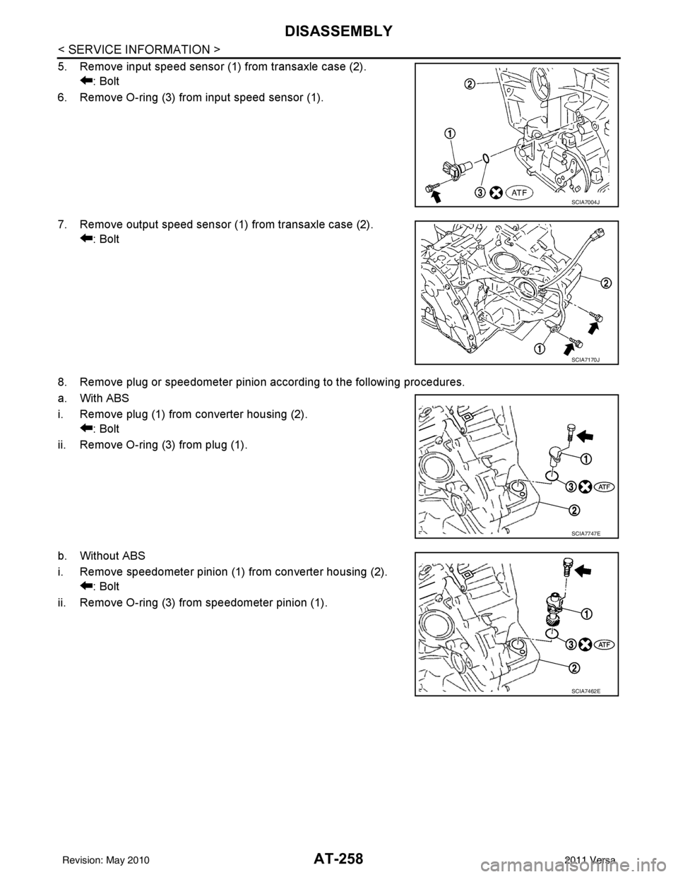
5. Remove input speed sensor (1) from transaxle case (2).: Bolt
6. Remove O-ring (3) from input speed sensor (1).
7. Remove output speed sensor (1) from transaxle case (2). : Bolt
8. Remove plug or speedometer pinion according to the following procedures.
a. With ABS
i. Remove plug (1) from converter housing (2). : Bolt
ii. Remove O-ring (3) from plug (1).
b. Without ABS
i. Remove speedometer pinion (1) from converter housing (2). : Bolt
ii. Remove O-ring (3) from speedometer pinion (1).
SCIA7004J
SCIA7170J
SCIA7747E
SCIA7462E
Revision: May 2010 2011 Versa