Engine support NISSAN TIIDA 2011 Service Repair Manual
[x] Cancel search | Manufacturer: NISSAN, Model Year: 2011, Model line: TIIDA, Model: NISSAN TIIDA 2011Pages: 3787, PDF Size: 78.35 MB
Page 94 of 3787

TROUBLE DIAGNOSISAT-77
< SERVICE INFORMATION >
DE
F
G H
I
J
K L
M A
B
AT
N
O P
*1: These terminals are connected to the data link connector.
*2: These terminals are connected to the ECM.
CONSULT-III Function (TRANSMISSION)INFOID:0000000005928105
CONSULT-III can display each diagnostic item using the diagnostic test models shown following.
FUNCTION
CONSULT-III REFERENCE VALUE
NOTICE:
1. The CONSULT-III electrically displays shift timi ng and lock-up timing (that is, operation timing of each
solenoid).
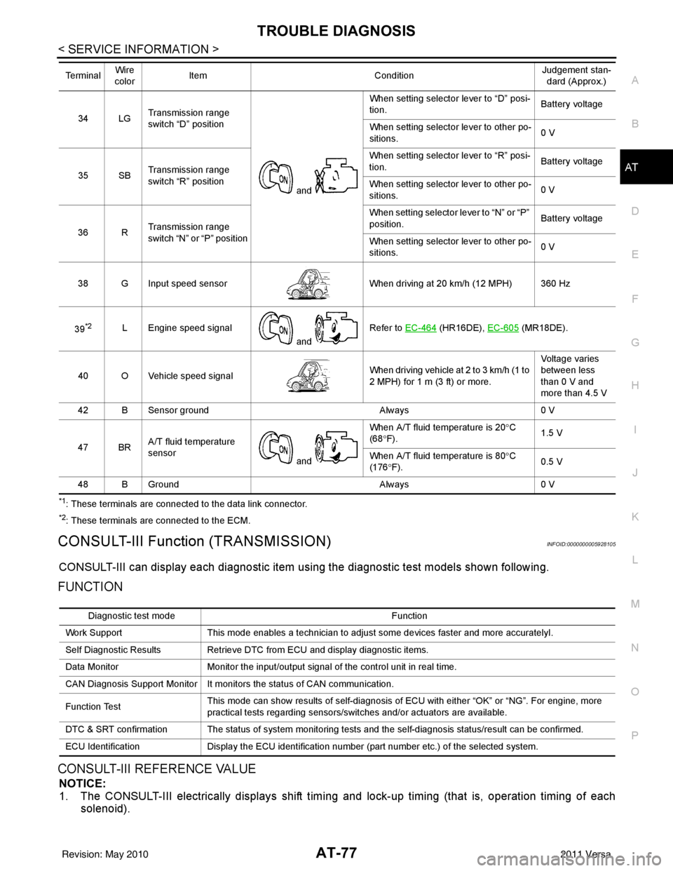
34 LG Transmission range
switch “D” position
and When setting selector lever to “D” posi-
tion.
Battery voltage
When setting selector lever to other po-
sitions. 0 V
35 SB Transmission range
switch “R” position When setting selector lever to “R” posi-
tion.
Battery voltage
When setting selector lever to other po-
sitions. 0 V
36 R Transmission range
switch “N” or “P” position When setting selector
lever to “N” or “P”
position. Battery voltage
When setting selector lever to other po-
sitions. 0 V
38 G Input speed sensor When driving at 20 km/h (12 MPH) 360 Hz
39
*2L Engine speed signal and Refer to EC-464 (HR16DE),
EC-605 (MR18DE).
40 O Vehicle speed signal When driving vehicle at 2 to 3 km/h (1 to
2 MPH) for 1 m (3 ft) or more.Voltage varies
between less
than 0 V and
more than 4.5 V
42 B Sensor ground Always0 V
47 BR A/T fluid temperature
sensor
and When A/T fluid temperature is 20°
C
(68 °F). 1.5 V
When A/T fluid temperature is 80° C
(176 °F). 0.5 V
48 B Ground Always0 V
Te r m i n a l
Wire
color Item
ConditionJudgement stan-
dard (Approx.)
Diagnostic test mode Function
Work Support This mode enables a technician to adjust some devices faster and more accuratelyI.
Self Diagnostic Results Retrieve DTC from ECU and display diagnostic items.
Data Monitor Monitor the input/output signal of the control unit in real time.
CAN Diagnosis Support Monitor It monitors the status of CAN communication.
Function Test This mode can show results of self-diagnosis of ECU with either “OK” or “NG”. For engine, more
practical tests regarding sensors/switches and/or actuators are available.
DTC & SRT confirmation The status of system monitoring tests and the self-diagnosis status/result can be confirmed.
ECU Identification Display the ECU identification number (part number etc.) of the selected system.
Revision: May 2010 2011 Versa
Page 98 of 3787

TROUBLE DIAGNOSISAT-81
< SERVICE INFORMATION >
DE
F
G H
I
J
K L
M A
B
AT
N
O P
CAN DIAGNOSTIC SUPPORT MONITOR MODE
Refer to LAN-14, "CAN Diagnostic Support Monitor".
DTC & SRT CONFIRMATION
Display Items List
2 POSITION SW (ON/OFF) X—
1 POSITION SW (ON/OFF) X—
ASCD-CRUISE (ON/OFF) X—
Signal input with CAN communication.
ASCD-OD CUT (ON/OFF) X—
KICKDOWN SW (ON/OFF) X—
Not mounted but displayed.
POWERSHIFT SW (ON/OFF) X—
CLOSED THL/SW (ON/OFF) X—
Signal input with CAN communication.
W/O THRL/P-SW (ON/OFF) X—
*SHIFT S/V A (ON/OFF) ——
Displays status of check signal (reinput
signal) for TCM control signal output. Re-
mains unchanged when solenoid valves
are open or shorted.
*SHIFT S/V B (ON/OFF)
——
*OVRRUN/C S/V (ON/OFF) ——
HOLD SW (ON/OFF) X— Not mounted but displayed.
BRAKE SW (ON/OFF) X— Stop lamp switch (Signal input with CAN
communication)
GEAR —X Gear position recognized by the TCM up-
dated after gear-shifting
SLCT LVR POSI —X Selector lever position is recognized by
the TCM.
For fail-safe operation, the specific value
used for control is displayed.
VEHICLE SPEED (km/h) —X Vehicle speed reco gnized by the TCM.
THROTTLE POSI (0.0/8) —X Degree of opening for accelerator recog-
nized by the TCM
For fail-safe operation, the specific value
used for control is displayed.
LINE PRES DTY (%) —X
TCC S/V DUTY (%) —X
SHIFT S/V A (ON/OFF) —X
SHIFT S/V B (ON/OFF) —X
OVERRUN/C S/V (ON/OFF) —X
SELF-D DP LMP (ON/OFF) —X
TC SLIP RATIO (0.000) ——
TC SLIP SPEED (rpm) —— Difference between engine speed and
torque converter input shaft speed
Monitored item (Unit)
Monitor Item Selection
Remarks
TCM INPUT
SIGNALS MAIN SIG-
NALS SELEC-
TION FROM
MENU
Revision: May 2010 2011 Versa
Page 260 of 3787

OVERHAULAT-243
< SERVICE INFORMATION >
DE
F
G H
I
J
K L
M A
B
AT
N
O P
MR18DE ENGINE MODELS
16. Servo release accumulator piston 17. Return spring
18. Control valve assembly
19. Oil pan gasket 20. Oil pan 21. Drain plug gasket
22. Drain plug 23. Magnet 24. Oil pan bolt
25. Snap ring 26. O-ring 27. O-ring
28. N-D accumulator piston 29. Return spring 30. O-ring
31. Lip seal 32. Input speed sensor 33. O-ring
34. Retaining pin 35. Detent spring 36. Retaining pin
37. Manual shaft 38. Manual shaft oil seal 39. Manual plate
40. Parking rod plate 41. Parking rod 42. OD servo piston retainer
43. Snap ring 44. O-ring 45. OD servo piston
46. D-ring 47. Servo release accumulator piston 48. O-ring
49. E-ring 50. Spring retainer 51. OD servo return spring
52. D-ring 53. Band servo piston 54. Band servo thrust washer
55. Band servo piston stem 56. 2nd servo return spring 57. Transmission range switch
58. Parking shaft 59. Return spring 60. Output gear adjusting spac-
er
61. Output gear bearing 62. Output gear 63. Side cover gasket
64. Side cover 65. Side cover bolt 66. Lock nut
67. Idler gear 68. Idler gear bearing 69. Reduction pinion gear ad-
justing shim
70. Parking actuator support 71. Parking pawl 72. LH differential side oil seal
73. Output speed sensor
: Apply Genuine Anaerobic Liquid Gasket or equivalent.
Revision: May 2010 2011 Versa
Page 267 of 3787

AT-250
< SERVICE INFORMATION >
OVERHAUL
Oil Channel
INFOID:0000000005928286
HR16DE ENGINE MODELS
19. Oil pan 20. Drain plug gasket21. Drain plug
22. Magnet 23. Oil pan bolt24. Snap ring
25. O-ring 26. O-ring27. N-D accumulator piston
28. Return spring 29. O-ring 30. Lip seal
31. Input speed sensor 32. O-ring 33. Retaining pin
34. Detent spring 35. Retaining pin 36. Manual shaft
37. Manual shaft oil seal 38. Manual plate 39. Parking rod plate
40. Parking rod 41. OD servo piston retainer42. Snap ring
43. O-ring 44. OD servo piston45. D-ring
46. Servo piston retainer 47. O-ring48. E-ring
49. Spring retainer 50. OD servo return spring 51. D-ring
52. Band servo piston 53. Band servo thrust washer 54. Band servo piston stem
55. 2nd servo return spring 56. Transmission range switch57. Parking shaft
58. Return spring 59. Thrust needle bearing60. Seal ring
61. Output shaft 62. Output shaft bearing63. Output shaft adjusting shim
64. Side cover 65. Side cover bolt 66. Lock nut
67. Idler gear 68. Idler gear bearing69. Reduction pinion gear adjusting
shim
70. Parking actuator support 71. Parking pawl 72. LH differential side oil seal
73. Output speed sensor
: Apply Genuine Anaerobic Liquid Gasket or equivalent.
Revision: May 2010 2011 Versa
Page 361 of 3787

AT-344
< SERVICE INFORMATION >
ASSEMBLY
ASSEMBLY
Assembly (1)INFOID:0000000005928303
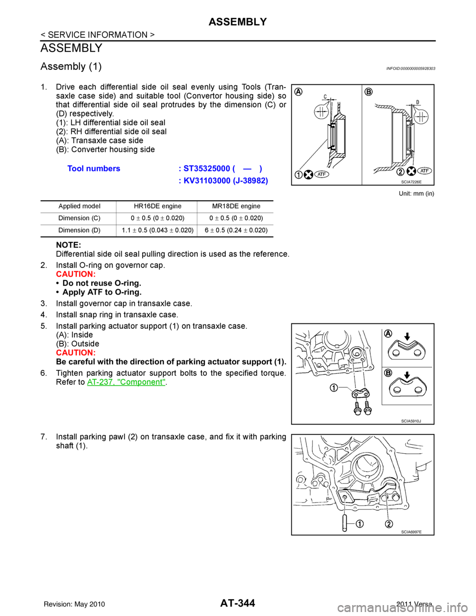
1. Drive each differential side oil seal evenly using Tools (Tran-saxle case side) and suitable tool (Convertor housing side) so
that differential side oil seal protrudes by the dimension (C) or
(D) respectively.
(1): LH differential side oil seal
(2): RH differential side oil seal
(A): Transaxle case side
(B): Converter housing side
Unit: mm (in)
NOTE:
Differential side oil seal pulling direction is used as the reference.
2. Install O-ring on governor cap. CAUTION:
• Do not reuse O-ring.
• Apply ATF to O-ring.
3. Install governor cap in transaxle case.
4. Install snap ring in transaxle case.
5. Install parking actuator support (1) on transaxle case. (A): Inside
(B): Outside
CAUTION:
Be careful with the direction of parking actuator support (1).
6. Tighten parking actuator support bolts to the specified torque. Refer to AT-237, "
Component".
7. Install parking pawl (2) on transaxle case, and fix it with parking shaft (1).Tool numbers
: ST35325000 ( — )
: KV31103000 (J-38982)
Applied model HR16DE engine MR18DE engine
Dimension (C) 0 ± 0.5 (0 ± 0.020) 0 ± 0.5 (0 ± 0.020)
Dimension (D) 1.1 ± 0.5 (0.043 ± 0.020) 6 ± 0.5 (0.24 ± 0.020)
SCIA7226E
SCIA5910J
SCIA6997E
Revision: May 2010 2011 Versa
Page 526 of 3787

BL-16
< SERVICE INFORMATION >
HOOD
Hood Lock Reinforcement
1. Remove front bumper. Refer to EI-15, "Removal and Installation".
2. Remove crash zone sensor. Refer to SRS-42, "
Removal and Installation".
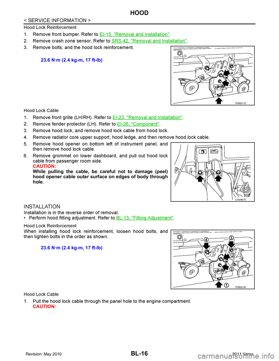
3. Remove bolts, and the hood lock reinforcement.
Hood Lock Cable
1. Remove front grille (LH/RH). Refer to EI-23, "Removal and Installation".
2. Remove fender protector (LH). Refer to EI-26, "
Component".
3. Remove hood lock, and remove hood lock cable from hood lock.
4. Remove radiator core upper support, hood ledge, and then remove hood lock cable.
5. Remove hood opener on bottom left of instrument panel, and then remove hood lock cable.
6. Remove grommet on lower dashboard, and pull out hood lock cable from passenger room side.
CAUTION:
While pulling the cable, be car eful not to damage (peel)
hood opener cable outer surface on edges of body through
hole.
INSTALLATION
Installation is in the reverse order of removal.
• Perform hood fitting adjustment. Refer to BL-13, "
Fitting Adjustment".
Hood Lock Reinforcement
When installing hood lock reinforcement, loosen hood bolts, and
then tighten bolts in the order as shown.
Hood Lock Cable
1. Pull the hood lock cable through the panel hole to the engine compartment. CAUTION: 23.6 N·m (2.4 kg-m, 17 ft-lb)
PIIB6511E
LIIA2667E
23.6 N·m (2.4 kg-m, 17 ft-lb)
PIIB6513E
Revision: May 2010
2011 Versa
Page 602 of 3787

BL-92
< SERVICE INFORMATION >
INTELLIGENT KEY SYSTEM
The headlamp flashes and the horn sounds intermittently.
The alarm automatically turns off:
• After 25 seconds
• When Intelligent Key unit receives any signal from remote controller of Intelligent Key
• When door request switch is pressed (Intelligent Key is outside vehicle)
Panic alarm function's press and holding time value can be changed in “PANIC ALARM DELAY” mode in
“WORK SUPPORT”. Refer to BL-117, "
CONSULT-III Application Item".
List of Operation Related Parts
Parts marked with × are the parts related to operation.
ENGINE START FUNCTION
When the registered Intelligent Key is carried, the engine can be started without inserting the key.
When ignition knob switch is ON (press ignition switch ), Intelligent Key unit searches Intelligent Key in the
vehicle using inside key antenna.
Then Intelligent Key is inside the vehicle, it performs the following operation.
• Illuminate green “KEY” warning lamp in combination meter.
• Released steering lock and ignition switch can be turned from OFF to ACC, ON or START position.
NOTE:
If Intelligent Key is not registered, “KEY” warning lamp in combination meter illuminates red.
• Intelligent Key sends engine start signal to BCM via CAN communication line.
When ignition switch turns to START position, BCM sends starter request signal to IPDM E/R. Then, engine
starts.
Remote keyless entry functions
Intelligent Key
Key switch
Ignition knob switch
Door request switch
Door switch
Back door lock assembly (back door switch)
Door lock actuator
Intelligent Key warning buzzer
Intelligent Key unit
CAN communication system
BCM
Hazard warning lamp
Horn
IPDM E/R
Head lamp
Door lock/unlock function by Intelligent Key button × ××× ×××
Hazard and buzzer reminder function ×××××
Auto door lock function ×× ××× ×××
Panic alarm function ×××× ××× ×××
WIIA1282E
Revision: May 2010 2011 Versa
Page 630 of 3787

BL-120
< SERVICE INFORMATION >
INTELLIGENT KEY SYSTEM
• Before performing the diagnosis in the following table, check “Trouble Diagnosis Procedure”. Refer to BL-
115, "Trouble Diagnosis Procedure".
• Make sure that vehicle is under the condition shown in “Conditions of vehicle” before starting diagnosis, and
check each symptom.
• If the following “symptoms” are detected, check systems shown in the “Diagnoses/service procedure” col- umn in this order.
Conditions of Vehicle (Operating Conditions)
• Intelligent Key is registered.
• Key is not inserted in ignition switch.
• One or more registered Intelligent Keys are in the vehicle.
KEY WARNING LAMP (RED) ILLUMINATES
NOTE:
• Before performing the diagnosis in the following table, check “Trouble Diagnosis Procedure”. Refer to BL-
115, "Trouble Diagnosis Procedure".
• Make sure that vehicle is under the condition shown in “Conditions of vehicle” before starting diagnosis, and
check each symptom.
• If the following “symptoms” are detected, check systems shown in the “Diagnoses/service procedure” col- umn in this order.
Conditions of Vehicle (Operating Conditions)
• Intelligent Key is registered.
• Key is not inserted in ignition switch.
• One or more registered Intelligent Keys are in the vehicle.
KEY WARNING LAMP DOES NOT ILLUMINATE
NOTE:
• Before performing the diagnosis in the following table, check “Trouble Diagnosis Procedure”. Refer to BL-
115, "Trouble Diagnosis Procedure".
• Make sure that vehicle is under the condition shown in “Conditions of vehicle” before starting diagnosis, and
check each symptom.
• If the following “symptoms” are detected, check systems shown in the “Diagnoses/service procedure” col- umn in this order.
• Check if ignition switch turns using mechanical key. If it turns, check if “ENGINE START BY I-KEY” in
“WORK SUPPORT” mode is ON.
Conditions of Vehicle (Operating Conditions)
• Intelligent Key is registered.
• Mechanical key is out of ignition switch.
• One or more registered Intelligent Keys are in the vehicle.
Symptom Diagnosis/service procedure Reference page
Ignition switch does not turn on with Intelligent Key.
[KEY warning lamp (g reen) illuminates]. 1. Check steering lock solenoid.
BL-147
2. Replace Intelligent Key unit.BL-158
SymptomDiagnosis/service procedure Reference page
Ignition switch does not turn on with Intelligent Key.
[KEY warning lamp (re d) illuminates]. 1. Check inside key antenna.
BL-146
2. Replace Intelligent Key unit.BL-158
SymptomDiagnosis/service procedureReference page
Ignition switch does not turn on with Intelligent Key.
[GREEN key warning lamp does not illuminate]. 1. Check Intelligent Key unit power supply and ground cir-
cuit. BL-126
2. Check ignition knob switch.
BL-129
3. Check key switch.BL-127
4. Check "KEY" warning lamp (GREEN). BL-155
5. Replace Intelligent Key unit. BL-158
Revision: May 2010 2011 Versa
Page 778 of 3787

BL-268
< SERVICE INFORMATION >
BODY REPAIR
4. Front pillar inner reinforcement (RH&LH)
5. Lower dash reinforcement
6. 4th crossmember (RH&LH)
7. Front side member rear extension (RH&LH)
8. 3rd crossmember (RH&LH)
9. Front seat outer rear bracket (RH&LH)
10. Front seat inner rear bracket (RH&LH)
11. 2nd crossmember (RH&LH)
12. Front seat outer front bracket (RH&LH)
13. Front seat inner front bracket (RH&LH)
14. Fender bracket (RH&LH)
15. Strut housing assembly RH
16. Cowl top side upper (RH&LH)
17. Front strut housing (RH&LH)
18. Upper torque rod reinforcement
19. Closing plate assembly RH
20. Engine mount reinforcement
21. Strut tower front reinforcement RH
22. Front hoodledge lower RH
23. Frame bracket outer (RH&LH)
24. Front bumper support bracket (RH&LH)
25. Closing plate (RH&LH)
26. Front suspension rear bracket (RH&LH)
27. Front side member outrigger (RH&LH)
28. Front side member assembly (RH&LH)
29. Front side member (RH&LH)
30. Frame bracket (RH&LH)
31. Closing plate assembly LH
32. Hoodledge connector (RH&LH)
33. Radiator core side support (RH&LH)
34. Radiator core support upper (RH&LH)
35. Hoodledge upper (RH&LH)
36. Hoodledge reinforcement assembly (RH&LH)
37. Dash side (RH&LH)
38. Dash side assembly (RH& LH)
39. Front floor reinforcement (RH&LH)
40. Front floor front (RH&LH)
41. Front floor center
42. Rear seat crossmember
43. Rear center crossmember
44. Rear seat upper crossmember
45. Rear side member (RH&LH)
46. Sill inner extension (RH&LH)
47. Rear side member extension (RH&LH)
48. Rear side member assembly (RH & LH)
49. Rear floor front
50. Rear floor front assembly
51. Rear floor side (RH&LH)
52. Rear floor rear
Revision: May 20102011 Versa
Page 908 of 3787
![NISSAN TIIDA 2011 Service Repair Manual TROUBLE DIAGNOSISBRC-19
< SERVICE INFORMATION > [ABS]
C
D
E
G H
I
J
K L
M A
B
BRC
N
O P
Note 1: Confirm tire pressure is normal.
Note 2: ON/OFF timing of ABS warning lamp
ON: For approximately 2 secon NISSAN TIIDA 2011 Service Repair Manual TROUBLE DIAGNOSISBRC-19
< SERVICE INFORMATION > [ABS]
C
D
E
G H
I
J
K L
M A
B
BRC
N
O P
Note 1: Confirm tire pressure is normal.
Note 2: ON/OFF timing of ABS warning lamp
ON: For approximately 2 secon](/img/5/57396/w960_57396-907.png)
TROUBLE DIAGNOSISBRC-19
< SERVICE INFORMATION > [ABS]
C
D
E
G H
I
J
K L
M A
B
BRC
N
O P
Note 1: Confirm tire pressure is normal.
Note 2: ON/OFF timing of ABS warning lamp
ON: For approximately 2 seconds after ignition switch is turned ON, or when a malfunction is detected.
OFF: Approximately 2 seconds after ignition switch is turned ON (when system is in normal operation).
CONSULT-III Function (ABS)INFOID:0000000005928445
CONSULT-III can display each diagnostic item using the diagnostic test modes shown following.
Monitor item Display content Data monitor
Note: Error inspection
checklist
Condition Reference value in
normal operation
FR RH SENSOR
FR LH SENSOR
RR RH SENSOR
RR LH SENSOR Wheel speedVehicle stopped
0 [km/h (MPH)]
BRC-25, "
Wheel Sensor
System"Vehicle running (Note 1) Almost in accor-
dance with speed-
ometer display
(within
±10%)
BATTERY VOLT Battery voltage sup-
plied to ABS actuator
and electric unit (con-
trol unit)Ignition switch ON
10 to 16VBRC-28, "
ABS Control
Unit Power and Ground
Systems Inspection"
STOP LAMP SW
Stop lamp switch oper-
ationBrake pedal depressed ON
—
Brake pedal not depressed OFF
ABS WARN LAMP ABS warning lamp ON
condition (Note 2)ABS warning lamp ON ON
BRC-17, "
Basic Inspec-
tion"ABS warning lamp OFF OFF
MOTOR RELAY Operation status of mo-
tor and motor relayIgnition switch ON or running
(ABS not activated)
OFF
BRC-27, "
Actuator Motor,
Motor Relay, and Circuit
Inspection"Ignition switch ON or engine
running (ABS activated) ON
ACTUATOR RLY Actuator relay opera-
tion statusVehicle stopped (Ignition
switch ON)
OFF
BRC-27, "
Actuator Motor,
Motor Relay, and Circuit
Inspection"Vehicle stopped (Engine run-
ning) ON
FR LH IN SOL
FR LH OUT SOL
FR RH IN SOL
FR RH OUT SOL
RR RH IN SOL
RR RH OUT SOL
RR LH IN SOL
RR LH OUT SOL Solenoid valve opera-
tionActuator (solenoid) is active
(“ACTIVE TEST” with CON-
SULT-III) or actuator relay is in-
active (in fail-safe mode).
ON
BRC-26, "
Solenoid Valve
System Inspection"When actuator (solenoid) is not
active and actuator relay is ac-
tive (ignition switch ON). OFF
ABS SIGNAL
EBD SIGNAL Signal statusABS active
EBD active
ON
ABS system
EBD system
ABS not active
EBD not active OFF
ABS FAIL SIG
EBD FAIL SIG Fail signal statusABS fail
EBD fail
ON
ABS system
EBD system
ABS normal
EBD normal OFF
Diagnostic mode
Description
SELF DIAGNOSTIC RESULT Displays ABS actuator and electric unit (control unit) self-diagnosis results. DATA MONITOR Displays ABS actuator and electric unit (control unit) input/output data in real time.
CAN DIAG SUPPORT MNTR The result of transmit/receive diagnosis of CAN communication can be read. ACTIVE TEST Operation of electrical loads can be checked by sending drive signal to them.
Revision: May 2010 2011 Versa