Set NISSAN TIIDA 2011 Service Repair Manual
[x] Cancel search | Manufacturer: NISSAN, Model Year: 2011, Model line: TIIDA, Model: NISSAN TIIDA 2011Pages: 3787, PDF Size: 78.35 MB
Page 3 of 3787

PLEASEHELPMAKETHISSERVICEMANUALBETTER!
YourcommentsareimportanttoNISSANandwillhelpustoimproveourServiceManuals.
UsethisformtoreportanyissuesorcommentsyoumayhaveregardingourServiceManuals.
Pleaseprintthisformandtypeorwriteyourcommentsbelow.Mailorfaxto:
NissanNorthAmerica,Inc.
TechnicalServiceInformation
39001SunriseDrive,P.O.Box9200
FarmingtonHills,MIUSA48331
FAX:(248)488-3910
SERVICEMANUAL:Model:Year:
PUBLICATIONNO.(Refer to Quick Reference Index ):
Pleasedescribeany Service Manualissuesorproblemsindetail:
Pagenumber(s)Note:Pleaseincludeacopyofeachpage,markedwithyourcomments.
Arethetroublediagnosisprocedureslogicalandeasytouse?(circleyouranswer)YESNO
Ifno,whatpagenumber(s)?Note:Pleaseincludeacopyofeachpage,markedwithyourcomments.
Pleasedescribetheissueorproblemindetail:
Istheorganizationofthemanualclearandeasytofollow?(circleyouranswer)YESNO
Pleasecomment:
WhatinformationshouldbeincludedinNISSANServiceManualstobettersupportyouinservicingor
repairingcustomervehicles?
DATE:YOURNAME:POSITION:
DEALER:DEALERNO.:ADDRESS:
CITY:STATE/PROV./COUNTRY:ZIP/POSTALCODE:
Page 28 of 3787
PREPARATIONAT-11
< SERVICE INFORMATION >
DE
F
G H
I
J
K L
M A
B
AT
N
O P
PREPARATION
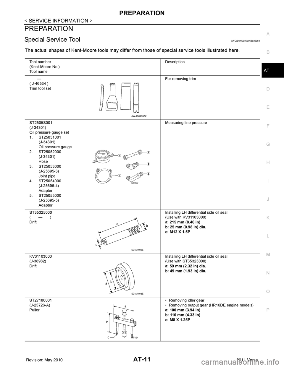
Special Service ToolINFOID:0000000005928068
The actual shapes of Kent-Moore tools may differ from those of special service tools illustrated here.
Tool number
(Kent-Moore No.)
Tool name Description
—
( J-46534 )
Trim tool set For removing trim
ST2505S001
(J-34301)
Oil pressure gauge set
1. ST25051001 (J-34301)
Oil pressure gauge
2. ST25052000 (J-34301)
Hose
3. ST25053000 (J-25695-3)
Joint pipe
4. ST25054000 (J-25695-4)
Adapter
5. ST25055000 (J-25695-5)
Adapter Measuring line pressure
ST35325000
( — )
Drift Installing LH differential side oil seal
(Use with KV31103000)
a: 215 mm (8.46 in)
b: 25 mm (0.98 in) dia.
c: M12 X 1.5P
KV31103000
(J-38982)
Drift Installing LH differential side oil seal
(Use with ST35325000)
a: 59 mm (2.32 in) dia.
b: 49 mm (1.93 in) dia.
ST27180001
(J-25726-A)
Puller • Removing idler gear
• Removing output gear (HR16DE engine models)
a: 100 mm (3.94 in)
b: 110 mm (4.33 in)
c: M8 X 1.25P
AWJIA0483ZZ
NT097
SCIA7102E
SCIA7103E
NT424
Revision: May 2010
2011 Versa
Page 31 of 3787
AT-14
< SERVICE INFORMATION >
PREPARATION
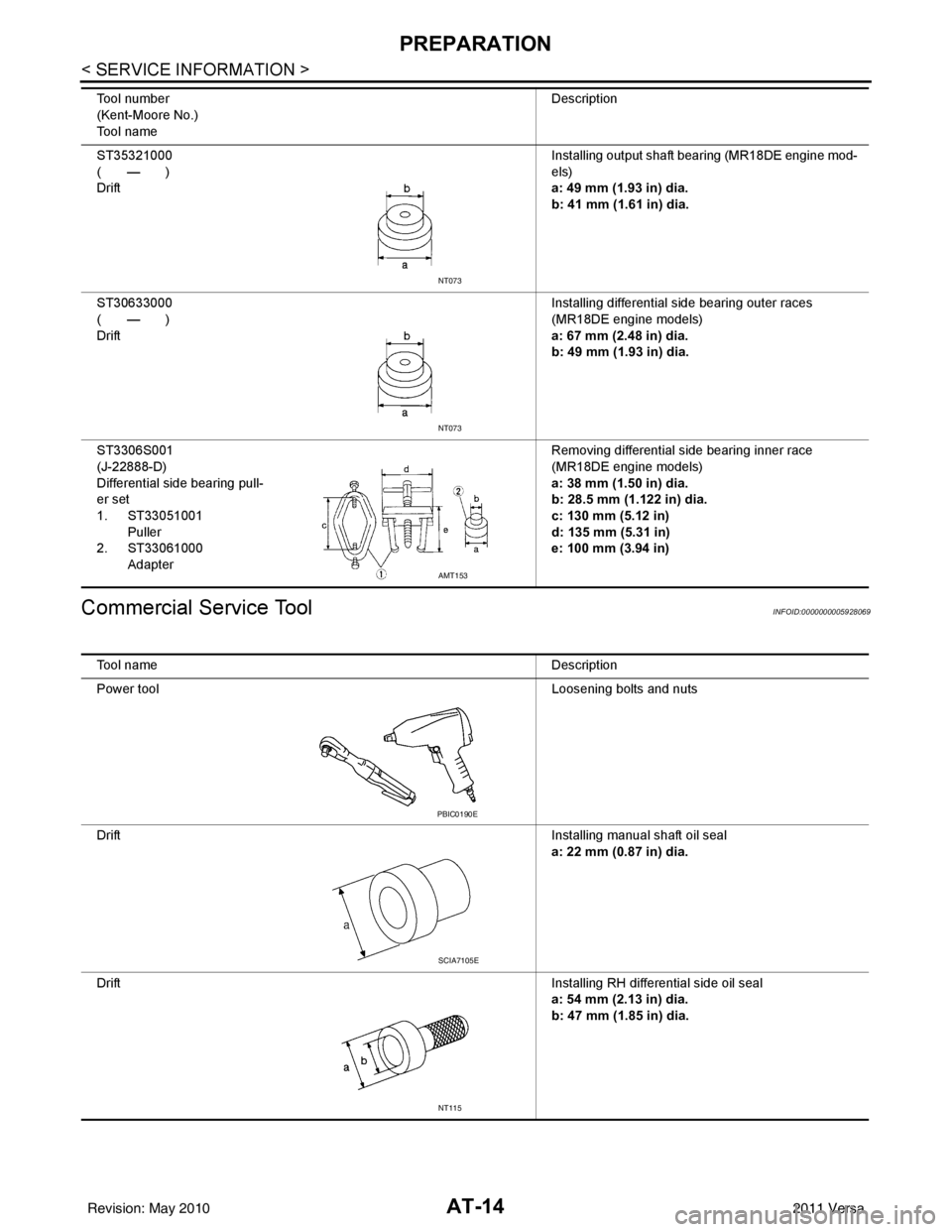
Commercial Service Tool
INFOID:0000000005928069
ST35321000
( — )
Drift Installing output shaft bearing (MR18DE engine mod-
els)
a: 49 mm (1.93 in) dia.
b: 41 mm (1.61 in) dia.
ST30633000
( — )
Drift Installing differential side bearing outer races
(MR18DE engine models)
a: 67 mm (2.48 in) dia.
b: 49 mm (1.93 in) dia.
ST3306S001
(J-22888-D)
Differential side bearing pull-
er set
1. ST33051001 Puller
2. ST33061000 Adapter Removing differential side bearing inner race
(MR18DE engine models)
a: 38 mm (1.50 in) dia.
b: 28.5 mm (1.122 in) dia.
c: 130 mm (5.12 in)
d: 135 mm (5.31 in)
e: 100 mm (3.94 in)
Tool number
(Kent-Moore No.)
Tool name
Description
NT073
NT073
AMT153
Tool name
Description
Power tool Loosening bolts and nuts
Drift Installing manual shaft oil seal
a: 22 mm (0.87 in) dia.
Drift Installing RH differential side oil seal
a: 54 mm (2.13 in) dia.
b: 47 mm (1.85 in) dia.
PBIC0190E
SCIA7105E
NT115
Revision: May 2010 2011 Versa
Page 34 of 3787
A/T FLUIDAT-17
< SERVICE INFORMATION >
DE
F
G H
I
J
K L
M A
B
AT
N
O P
A/T FLUID
Checking A/T FluidINFOID:0000000005928070
1. Warm up engine.
2. Check for A/T fluid leakage.
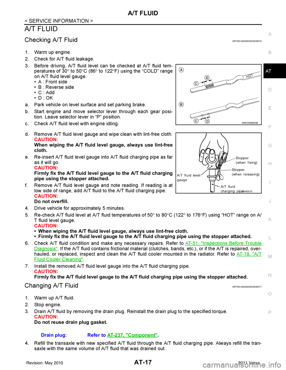
3. Before driving, A/T fluid level can be checked at A/T fluid tem- peratures of 30° to 50°C (86° to 122° F) using the “COLD” range
on A/T fluid level gauge.
• A : Front side
• B : Reverse side
•C : Add
• D : OK
a. Park vehicle on level surface and set parking brake.
b. Start engine and move selector lever through each gear posi- tion. Leave selector lever in “P” position.
c. Check A/T fluid level with engine idling.
d. Remove A/T fluid level gauge and wipe clean with lint-free cloth. CAUTION:
When wiping the A/T fluid l evel gauge, always use lint-free
cloth.
e. Re-insert A/T fluid level gauge into A/T fluid charging pipe as far as it will go.
CAUTION:
Firmly fix the A/T fluid level ga uge to the A/T fluid charging
pipe using the stopper attached.
f. Remove A/T fluid level gauge and note reading. If reading is at low side of range, add A/T fluid to the A/T fluid charging pipe.
CAUTION:
Do not overfill.
4. Drive vehicle for approximately 5 minutes.
5. Re-check A/T fluid level at A/T fluid temperatures of 50° to 80 °C (122° to 176°F) using “HOT” range on A/
T fluid level gauge.
CAUTION:
• When wiping the A/T fluid level gauge, always use lint-free cloth.
• Firmly fix the A/T fluid level ga uge to the A/T fluid charging pipe using the stopper attached.
6. Check A/T fluid condition and make any necessary repairs. Refer to AT-51, "
Inspections Before Trouble
Diagnosis". If the A/T fluid contains frictional material (clutches, bands, etc.), or if the A/T is repaired, over-
hauled, or replaced, inspect and clean the A/T fluid cooler mounted in the radiator. Refer to AT-18, "
A/T
Fluid Cooler Cleaning".
7. Install the removed A/T fluid level gauge into the A/T fluid charging pipe. CAUTION:
Firmly fix the A/T fluid level gaug e to the A/T fluid charging pipe using the stopper attached.
Changing A/T FluidINFOID:0000000005928071
1. Warm up A/T fluid.
2. Stop engine.
3. Drain A/T fluid by removing the drain plug. Re install the drain plug to the specified torque.
CAUTION:
Do not reuse drain plug gasket.
4. Refill the transaxle with new specified A/T fluid through the A/T fluid charging pipe. Always refill the tran- saxle with the same volume of A/T fluid that was drained out.
AWDIA0660GB
SMA051D
Drain plug: Refer to AT-237, "Component".
Revision: May 2010 2011 Versa
Page 49 of 3787
AT-32
< SERVICE INFORMATION >
A/T CONTROL SYSTEM
*1: Output speed sensor
*2: Spare for accelerator pedal position signal
*3: If these input and output signals are different, the TCM triggers the fail-safe function.
*4: Used as a condition for starting self-diagnostics; if self-diagnosis are not started, it is judged that there is some kind of error.
*5: Input by CAN communications.
*6: Output by CAN communications.
Line Pressure ControlINFOID:0000000005928078
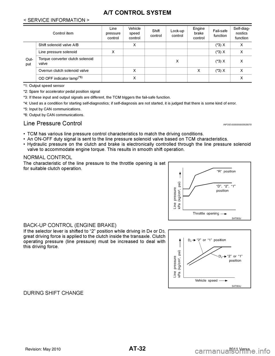
• TCM has various line pressure control char acteristics to match the driving conditions.
• An ON-OFF duty signal is sent to the line pres sure solenoid valve based on TCM characteristics.
• Hydraulic pressure on the clutch and brake is electronically controlled through the line pressure solenoid valve to accommodate engine torque. This results in smooth shift operation.
NORMAL CONTROL
The characteristic of the line pressure to the throttle opening is set
for suitable clutch operation.
BACK-UP CONTROL (ENGINE BRAKE)
If the selector lever is shifted to “2” position while driving in D4 or D3,
great driving force is applied to the clutch inside the transaxle. Clutch
operating pressure (line pressure) must be increased to deal with
this driving force.
DURING SHIFT CHANGE
Out-
put Shift solenoid valve A/B
X(*3) X X
Line pressure solenoid X (*3) X X
Torque converter clutch solenoid
valve X(
*3 ) X X
Overrun clutch solenoid valve XX (*3) X X
OD OFF indicator lamp
(*6)XX
Control item
Line
pressure
control Vehicle
speed
control Shift
control Lock-up
control Engine
brake
control Fail-safe
function Self-diag-
nostics
function
SAT003J
SAT004J
Revision: May 2010 2011 Versa
Page 50 of 3787
A/T CONTROL SYSTEMAT-33
< SERVICE INFORMATION >
DE
F
G H
I
J
K L
M A
B
AT
N
O P
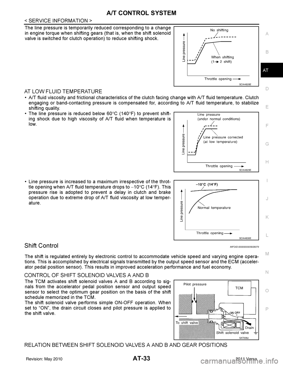
The line pressure is temporarily reduced corresponding to a change
in engine torque when shifting gears (that is, when the shift solenoid
valve is switched for clutch operation) to reduce shifting shock.
AT LOW FLUID TEMPERATURE
• A/T fluid viscosity and frictional characteristics of t he clutch facing change with A/T fluid temperature. Clutch
engaging or band-contacting pressure is compensated for, according to A/T fluid temperature, to stabilize
shifting quality.
• The line pressure is reduced below 60 °C (140° F) to prevent shift-
ing shock due to high viscosity of A/T fluid when temperature is
low.
• Line pressure is increased to a maximum irrespective of the throt- tle opening when A/T fluid temperature drops to −10° C (14° F). This
pressure rise is adopted to prevent a delay in clutch and brake
operation due to extreme drop of A/T fluid viscosity at low temper-
ature.
Shift ControlINFOID:0000000005928079
The shift is regulated entirely by electronic cont rol to accommodate vehicle speed and varying engine opera-
tions. This is accomplished by electrical signals trans mitted by the output speed sensor and the ECM (acceler-
ator pedal position sensor). This results in improved acceleration performance and fuel economy.
CONTROL OF SHIFT SOLENOID VALVES A AND B
The TCM activates shift solenoid valves A and B according to sig-
nals from the accelerator pedal position sensor and output speed
sensor to select the optimum gear position on the basis of the shift
schedule memorized in the TCM.
The shift solenoid valve performs simple ON-OFF operation. When
set to “ON”, the drain circuit closes and pilot pressure is applied to
the shift valve.
RELATION BETWEEN SHIFT SOLENOID VALVES A AND B AND GEAR POSITIONS
SCIA4828E
SCIA4829E
SCIA4830E
SAT008J
Revision: May 2010 2011 Versa
Page 51 of 3787
AT-34
< SERVICE INFORMATION >
A/T CONTROL SYSTEM
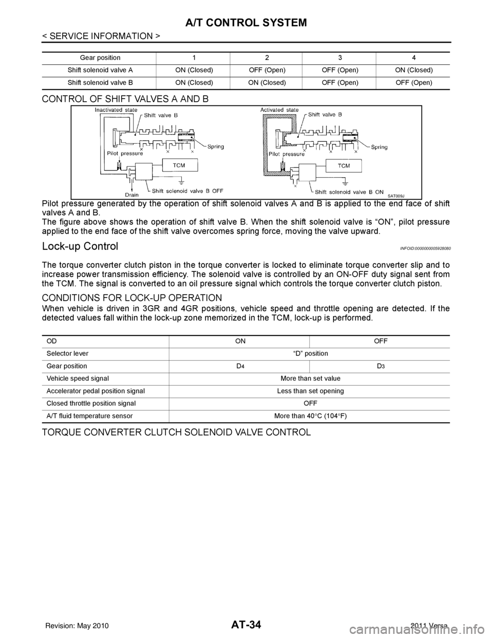
CONTROL OF SHIFT VALVES A AND B
Pilot pressure generated by the operation of shift solenoid valves A and B is applied to the end face of shift
valves A and B.
The figure above shows the operation of shift valve B. When the shift solenoid valve is “ON”, pilot pressure
applied to the end face of the shift valve overcomes spring force, moving the valve upward.
Lock-up ControlINFOID:0000000005928080
The torque converter clutch piston in the torque conver ter is locked to eliminate torque converter slip and to
increase power transmission efficiency. The solenoid va lve is controlled by an ON-OFF duty signal sent from
the TCM. The signal is converted to an oil pressure si gnal which controls the torque converter clutch piston.
CONDITIONS FOR LOCK-UP OPERATION
When vehicle is driven in 3GR and 4GR positions, v ehicle speed and throttle opening are detected. If the
detected values fall within the lock-up zone me morized in the TCM, lock-up is performed.
TORQUE CONVERTER CLUTCH SOLENOID VALVE CONTROL
Gear position123 4
Shift solenoid valve A ON (Closed)OFF (Open)OFF (Open) ON (Closed)
Shift solenoid valve B ON (Closed)ON (Closed) OFF (Open) OFF (Open)
SAT009J
OD ONOFF
Selector lever “D” position
Gear position D
4D3
Vehicle speed signal More than set value
Accelerator pedal position signal Less than set opening
Closed throttle position signal OFF
A/T fluid temperature sensor More than 40°C (104 °F)
Revision: May 2010 2011 Versa
Page 52 of 3787
A/T CONTROL SYSTEMAT-35
< SERVICE INFORMATION >
DE
F
G H
I
J
K L
M A
B
AT
N
O P
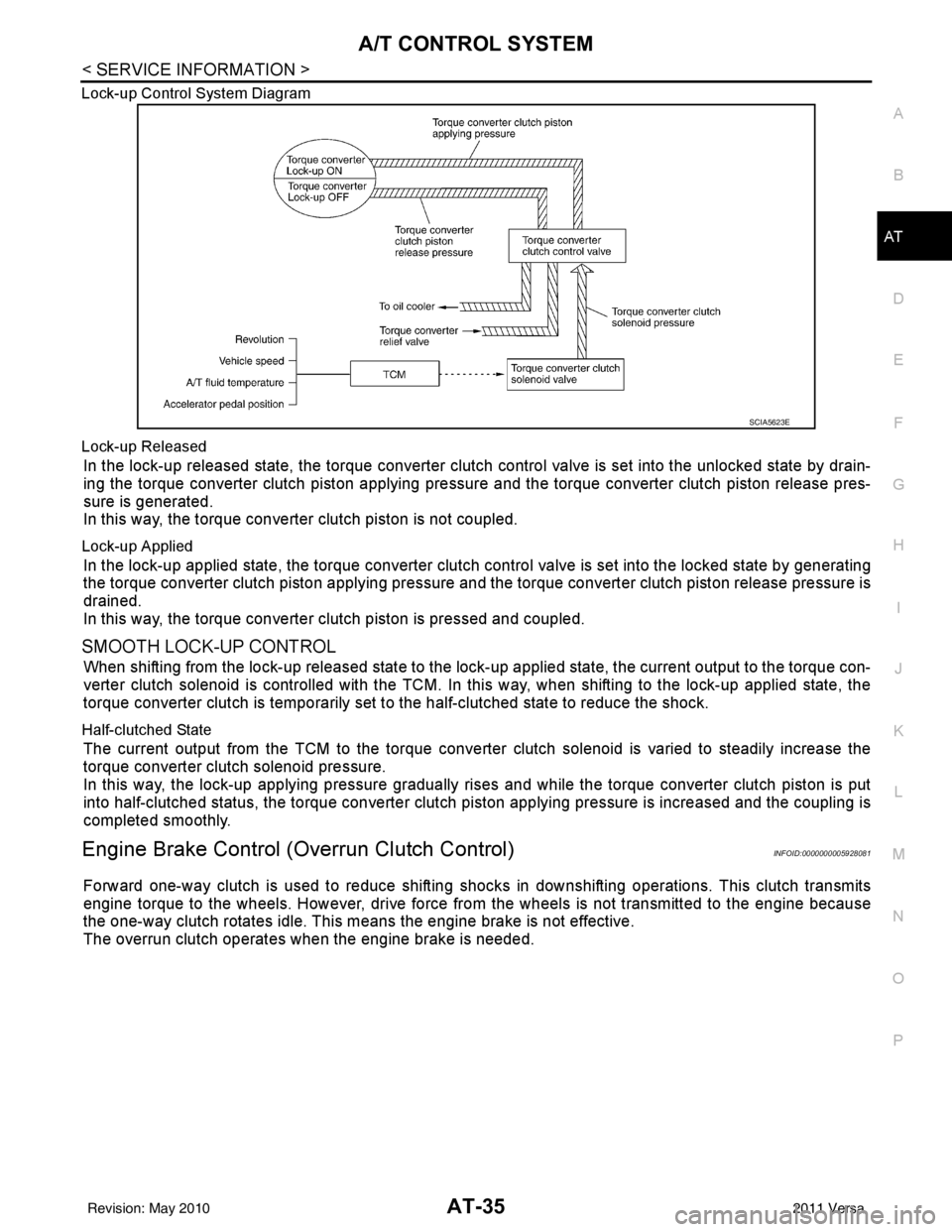
Lock-up Control System Diagram
Lock-up Released
In the lock-up released state, the torque converter clutch control valve is set into the unlocked state by drain-
ing the torque converter clutch piston applying pressure and the torque converter clutch piston release pres-
sure is generated.
In this way, the torque converter clutch piston is not coupled.
Lock-up Applied
In the lock-up applied state, the torque converter clutch
control valve is set into the locked state by generating
the torque converter clutch piston applying pressure and t he torque converter clutch piston release pressure is
drained.
In this way, the torque converter clutch piston is pressed and coupled.
SMOOTH LOCK-UP CONTROL
When shifting from the lock-up released state to the lock-up applied state, the current output to the torque con-
verter clutch solenoid is controlled with the TCM. In this way, when shifting to the lock-up applied state, the
torque converter clutch is temporarily set to the half-clutched state to reduce the shock.
Half-clutched State
The current output from the TCM to the torque converte r clutch solenoid is varied to steadily increase the
torque converter clutch solenoid pressure.
In this way, the lock-up applying pressure gradually rises and while the torque converter clutch piston is put
into half-clutched status, the torque converter clutch piston applying pressure is increased and the coupling is
completed smoothly.
Engine Brake Control (Overrun Clutch Control)INFOID:0000000005928081
Forward one-way clutch is used to reduce shifting shoc ks in downshifting operations. This clutch transmits
engine torque to the wheels. However, drive force fr om the wheels is not transmitted to the engine because
the one-way clutch rotates idle. This means the engine brake is not effective.
The overrun clutch operates when the engine brake is needed.
SCIA5623E
Revision: May 2010 2011 Versa
Page 57 of 3787

AT-40
< SERVICE INFORMATION >
ON BOARD DIAGNOSTIC (OBD) SYSTEM
Data which are stored in the ECM memory, along with the 1st trip DTC, are called 1st trip freeze frame data,
and the data, stored together with the DTC data, are called freeze frame data and displayed on CONSULT-III
or GST. The 1st trip freeze frame data can only be disp layed on the CONSULT-III screen, not on the GST. For
detail, refer to EC-106, "
CONSULT-III Function" (HR16DE), EC-612, "CONSULT-III Function (ENGINE)"
(MR18DE).
Only one set of freeze frame data (either 1st trip freeze frame data of freeze frame data) can be stored in the
ECM. 1st trip freeze frame data is stored in the ECM memory along with the 1st trip DTC. There is no priority
for 1st trip freeze frame data and it is updated each time a different 1st trip DTC is detected. However, once
freeze frame data (2nd trip detection/MIL on) is stored in the ECM memory, 1st trip freeze frame data is no
longer stored. Remember, only one set of freeze frame data can be stored in the ECM. The ECM has the fol-
lowing priorities to update the data.
Both 1st trip freeze frame data and freeze frame dat a (along with the DTC) are cleared when the ECM mem-
ory is erased.
HOW TO ERASE DTC
The diagnostic trouble code can be erased by CONSULT- III, GST or ECM DIAGNOSTIC TEST MODE as
described following.
• If the battery cable is disconnected, the diagnosti c trouble code will be cleared within 24 hours.
• When you erase the DTC, using CONSULT-III or GS T is easier and quicker than switching the mode
selector on the ECM.
The following emission-related diagnostic information is cleared from the ECM memory when erasing DTC
related to OBD-II. For details, refer to EC-95, "
Diagnosis Description" (HR16DE), EC-542, "Emission-related
Diagnostic Information" (MR18DE).
• Diagnostic trouble codes (DTC)
• 1st trip diagnostic trou ble codes (1st trip DTC)
• Freeze frame data
• 1st trip freeze frame data
• System readiness test (SRT) codes
• Test values
HOW TO ERASE DTC (WITH CONSULT-III)
•If a DTC is displayed for both ECM and TCM, it is necessary to be erased for both ECM and TCM.
1. If the ignition switch stays ON after repair work, be sure to turn ignition switch OFF once. Wait at least 10 seconds and then turn it ON (engine stopped) again.
2. Turn CONSULT-III “ON” and touch “TRANSMISSION”.
3. Touch “SELF-DIAG RESULTS”.
4. Touch “ERASE”. (The DTC in the TCM will be erased.) Then touch “BACK” twice.
5. Touch “ENGINE”.
6. Touch “SELF-DIAG RESULTS”.
7. Touch “ERASE”. (The DTC in the ECM will be erased.)
HOW TO ERASE DTC (WITH GST)
1. If the ignition switch stays ON after repair work, be sure to turn ignition switch OFF once. Wait at least 10 seconds and then turn it ON (engine stopped) again.
2. Perform “TCM SELF-DIAGNOSTIC PROCEDURE (No Tools)”. Refer to AT-82, "
Diagnosis Procedure
without CONSULT-III". (The engine warm-up step can be skipped when performing the diagnosis only\
to
erase the DTC.)
3. Select Mode 4 with Generic Scan Tool (GST). For details, refer to EC-103, "
On Board Diagnosis Function"
(HR16DE), EC-618, "Generic Scan Tool (GST) Function" (MR18DE).
HOW TO ERASE DTC (NO TOOLS)
Priority Items
1 Freeze frame data Misfire — DTC: P0300 - P0306
Fuel Injection System Function — DTC: P0171, P0172, P0174, P0175
2 Except the above items (Includes A/T related items)
3 1st trip freeze frame data
Revision: May 2010 2011 Versa
Page 68 of 3787
TROUBLE DIAGNOSISAT-51
< SERVICE INFORMATION >
DE
F
G H
I
J
K L
M A
B
AT
N
O P
Inspections Before Trouble DiagnosisINFOID:0000000005928094
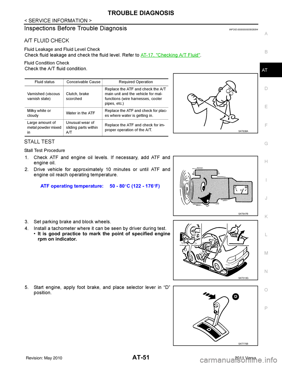
A/T FLUID CHECK
Fluid Leakage and Fluid Level Check
Check fluid leakage and check the fluid level. Refer to AT-17, "Checking A/T Fluid".
Fluid Condition Check
Check the A/T fluid condition.
STALL TEST
Stall Test Procedure
1. Check ATF and engine oil levels. If necessary, add ATF and engine oil.
2. Drive vehicle for approximately 10 minutes or until ATF and engine oil reach operating temperature.
3. Set parking brake and block wheels.
4. Install a tachometer where it can be seen by driver during test. •It is good practice to mark the point of specified engine
rpm on indicator.
5. Start engine, apply foot brake, and place selector lever in “D” position.
Fluid status Conceivable Cause Required Operation
Varnished (viscous
varnish state) Clutch, brake
scorchedReplace the ATF and check the A/T
main unit and the vehicle for mal-
functions (wire harnesses, cooler
pipes, etc.)
Milky white or
cloudy Water in the ATFReplace the ATF and check for plac-
es where water is getting in.
Large amount of
metal powder mixed
in Unusual wear of
sliding parts within
A/T
Replace the ATF and check for im-
proper operation of the A/T.
SAT638A
ATF operating temperature: 50 - 80
°C (122 - 176 °F)
SAT647B
SAT513G
SAT775B
Revision: May 2010 2011 Versa