Trunk lid assembly NISSAN TIIDA 2011 Service Repair Manual
[x] Cancel search | Manufacturer: NISSAN, Model Year: 2011, Model line: TIIDA, Model: NISSAN TIIDA 2011Pages: 3787, PDF Size: 78.35 MB
Page 498 of 3787

BCS-8
< SERVICE INFORMATION >
BCM (BODY CONTROL MODULE)
CAN Communication System Description
INFOID:0000000005929256
Refer to LAN-7, "System Description".
Panic alarm •Key switch
•KeyfobIPDM E/R
Vehicle security system • All door switches
•Keyfob
• Door lock/unlock switch
• Trunk key cylinder switch (Se-
dan)
• Front door key cylinder switch LH • IPDM/ER
• Security indicator lamp
Battery save r control • Ignition switch
• Combination switch
IPDM E/R
Headlamp Combination switch IPDM E/R
Tail lamp Combination switchIPDM E/R
Front fog lamp (with front fog lamps) Combination switch IPDM E/R
Turn signal lamp Combination switch• Turn signal lamp
• Combination meter
Hazard lamp Hazard switch• Turn signal lamp
• Combination meter
Room lamp timer •Key switch
•Keyfob
• Main power window and door
lock/unlock switch
• Front door switch LH
• All door switch Interior room lamp
Back door switch signal (Hatchback) Back door lock assembly Luggage room lamp
Back door lock signal (Hatchback) Back door lock assembly Back door opener
Trunk lamp switch signal (Sedan) Trunk lamp switch and trunk re-
lease solenoidLuggage room lamp
Trunk lid opener signal (Sedan) Trunk lamp switch and trunk re-
lease solenoid
Trunk lid opener
Key warning chime •Key switch
• Front door switch LHCombination meter (warning buzzer)
Light warning chime • Combination switch
•Key switch
• Front door switch LHCombination meter (warning buzzer)
Seat belt warning chime • Seat belt buckle switch LH
• Ignition switch
Combination meter (warning buzzer)
Front wiper and washer system • Combination switch
• Ignition switchIPDM E/R
Rear window defogger Rear window defogger switch IPDM E/R
Rear wiper and washer system
(Hatchback) • Combination switch
• Ignition switch
Rear wiper motor
A/C switch signal Front air controlECM
Blower fan switch signal Front air controlECM
A/C indicator signal Front air controlA/C indicator
Low tire pressure warning system Remote keyless entry receiver Combination meter System
Input Output
Revision: May 2010 2011 Versa
Page 512 of 3787

BL-2
Keyfob Function (Lock) Check ...............................82
Keyfob Function (Unlock) Check ............................82
ID Code Entry Procedure .................................... ...83
Keyfob Battery Replacement ............................... ...85
Removal and Installation of Remote Keyless Entry
Receiver .............................................................. ...
85
INTELLIGENT KEY SYSTEM ............................86
Component Parts and Harness Connector Loca-
tion ....................................................................... ...
86
System Description .................................................88
CAN Communication System Description ..............95
Schematic ............................................................ ...96
Wiring Diagram - I/KEY - ..................................... ...98
Intelligent Key Unit Har ness Connector Terminal
Layout .................................................................. ..
108
Terminal and Reference Value for Intelligent Key
Unit ........................................................................
108
Steering Lock Solenoid Harness Connector Ter-
minal Layout ..........................................................
110
Terminal and Reference Value for Steering Lock
Solenoid .................................................................
110
Terminal and Reference Value for BCM ................111
Trouble Diagnosis Procedure ................................115
CONSULT-III Functions (INTELLIGENT KEY) ......117
CONSULT-III Application Item ............................. ..117
Trouble Diagnosis Symptom Chart ........................119
CAN Communication System Inspection ...............126
Power Supply and Ground Circuit Inspection ........126
Key Switch (Intelligent Key Unit Input) Check .......127
Key Switch (BCM Input) Check .............................128
Ignition Knob Switch Check ................................. ..129
Door Switch Check (Hatchback) ............................131
Door Switch Check (Sedan) ..................................134
Door Request Switch Check ..................................135
Back Door Request Switch Check (Hatchback) ....137
Trunk Opener Request Switch Check (Sedan) ... ..138
Unlock Sensor Check ............................................140
Intelligent Key Warning Buzzer(s) Check ..............142
Outside Key Antenna (Dri ver Side and Passenger
Side) Check ......................................................... ..
143
Outside Key Antenna (Rear Bumper) Check .........144
Inside Key Antenna Check ....................................146
Steering Lock Solenoid Check ............................ ..147
Key Interlock Solenoid (With M/T) Check ..............149
Ignition Switch Position Check ............................ ..150
Stop Lamp Switch Check (With CVT or A/T) ....... ..150
Stop Lamp Switch Check (With M/T) .....................152
CVT or A/T Shift Selector (Park Position Switch)
Check .................................................................. ..
153
"P-SHIFT" Warning Lamp (With CVT or A/T)
Check ....................................................................
154
"LOCK" Warning Lamp (With M/T) Check .............155
"KEY" Warning Lamp (RED) Check ......................155
"KEY" Warning Lamp (G REEN) Check .................155
Check Warning Chime in Combination Meter ........156
Hazard Function Check .........................................156
Horn Function Check .... .........................................157
Headlamp Function Chec k ....................................157
Intelligent Key Battery Re placement .....................158
Remote Keyless Entry Func tion ............................158
Removal and Installation of Intelligent Key Unit ... .158
DOOR ...............................................................160
Fitting Adjustment ................................................ .160
Removal and Installation .......................................163
Back Door Stay Disposal ..................................... .166
FRONT DOOR LOCK .......................................167
Component Parts Location .................................. .167
Removal and Installation .......................................167
REAR DOOR LOCK ....................................... ..170
Component Parts Location .................................. .170
Removal and Installation .......................................170
BACK DOOR LOCK ....................................... ..173
Component Parts and Harness Connector Loca-
tion ....................................................................... .
173
System Description ...............................................173
Wiring Diagram - B/DOOR - ..................................174
Terminal and Reference Value for BCM ...............176
Terminal and Reference Value for Intelligent Key
Unit ....................................................................... .
180
CONSULT-III Function (BCM) ..............................182
Work Flow .............................................................183
Trouble Diagnosis Chart by Symptom ..................183
BCM Power Supply and Ground Circuit Inspection
.
183
Check Back Door Opener Switch Circuit (Without
Intelligent Key or Power Windows) ...................... .
184
Check Back Door Opener Switch Circuit (Without
Intelligent Key, with Power Windows) .................. .
187
Check Back Door Opener Switch Circuit (With In-
telligent Key) ........................................................ .
189
Check Back Door Lock Assembly (Actuator) Cir-
cuit ........................................................................
191
Removal and Installation .......................................193
TRUNK LID ..................................................... ..195
Fitting Adjustment ................................................ .195
Trunk Lid Assembly ..............................................195
Trunk Lid Lock ......................................................196
Trunk Lid Striker ....................................................196
TRUNK LID OPENER .......................................198
Component Parts and Harness Connector Loca-
tion ....................................................................... .
198
System Description ...............................................198
Wiring Diagram - TLID - ........................................199
Terminal and Reference Value for BCM ...............201
Terminal and Reference Value for Intelligent Key
Unit ....................................................................... .
205
CONSULT-III Function (BCM) ..............................207
Work Flow .............................................................208
Trouble Diagnosis Chart by Symptom ..................208
BCM Power Supply and Ground Circuit Inspection
.
208
Revision: May 2010 2011 Versa
Page 705 of 3787
TRUNK LIDBL-195
< SERVICE INFORMATION >
C
DE
F
G H
J
K L
M A
B
BL
N
O P
TRUNK LID
Fitting AdjustmentINFOID:0000000005929393
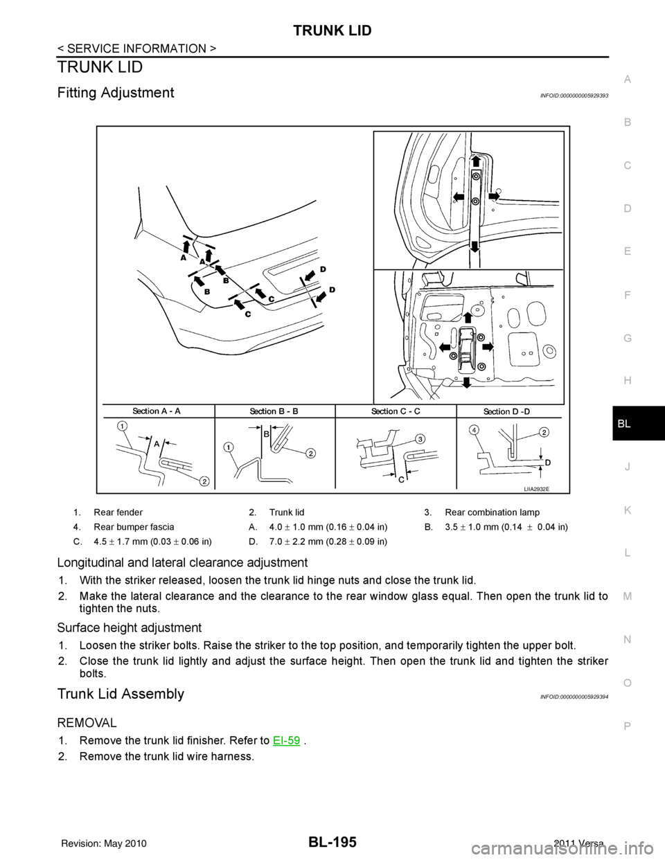
Longitudinal and latera l clearance adjustment
1. With the striker released, loosen the trunk lid hinge nuts and close the trunk lid.
2. Make the lateral clearance and the clearance to the rear window glass equal. Then open the trunk lid to
tighten the nuts.
Surface height adjustment
1. Loosen the striker bolts. Raise the striker to t he top position, and temporarily tighten the upper bolt.
2. Close the trunk lid lightly and adjust the surface height. Then open the trunk lid and tighten the striker bolts.
Trunk Lid AssemblyINFOID:0000000005929394
REMOVAL
1. Remove the trunk lid finisher. Refer to EI-59 .
2. Remove the trunk lid wire harness.
1. Rear fender 2. Trunk lid3. Rear combination lamp
4. Rear bumper fascia A. 4.0 ± 1.0 mm (0.16 ± 0.04 in) B. 3.5 ± 1.0 mm (0.14 ± 0.04 in)
C. 4.5 ± 1.7 mm (0.03 ± 0.06 in) D. 7.0 ± 2.2 mm (0.28 ± 0.09 in)
LIIA2932E
Revision: May 2010 2011 Versa
Page 706 of 3787
BL-196
< SERVICE INFORMATION >
TRUNK LID
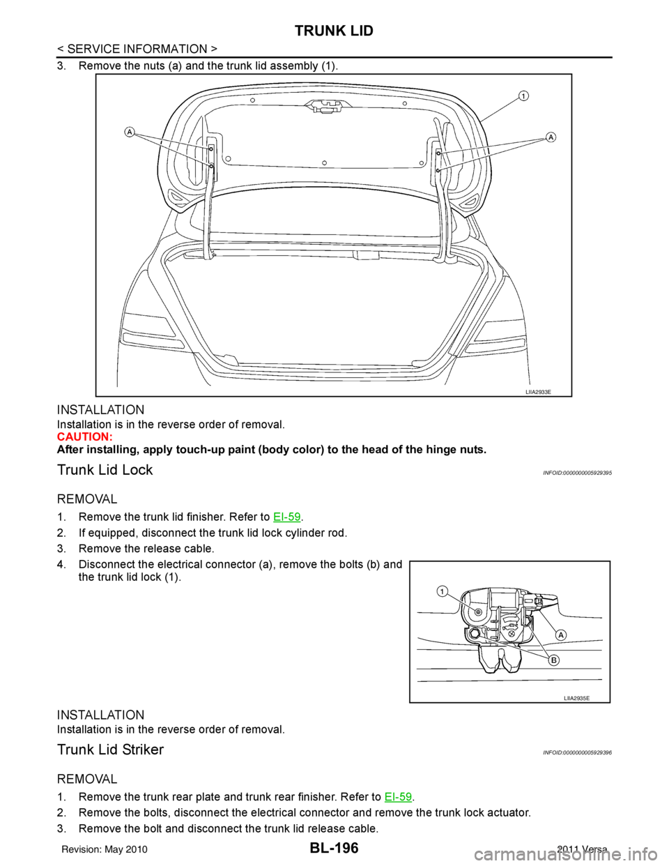
3. Remove the nuts (a) and the trunk lid assembly (1).
INSTALLATION
Installation is in the reverse order of removal.
CAUTION:
After installing, apply touch-up paint (body color) to the head of the hinge nuts.
Trunk Lid LockINFOID:0000000005929395
REMOVAL
1. Remove the trunk lid finisher. Refer to EI-59.
2. If equipped, disconnect the trunk lid lock cylinder rod.
3. Remove the release cable.
4. Disconnect the electrical connector (a), remove the bolts (b) and the trunk lid lock (1).
INSTALLATION
Installation is in the reverse order of removal.
Trunk Lid StrikerINFOID:0000000005929396
REMOVAL
1. Remove the trunk rear plate and trunk rear finisher. Refer to EI-59.
2. Remove the bolts, disconnect the electrical connector and remove the trunk lock actuator.
3. Remove the bolt and disconnect the trunk lid release cable.
LIIA2933E
LIIA2935E
Revision: May 2010 2011 Versa
Page 708 of 3787
BL-198
< SERVICE INFORMATION >
TRUNK LID OPENER
TRUNK LID OPENER
Component Parts and Harness Connector LocationINFOID:0000000005929397
System DescriptionINFOID:0000000005929398
Power is supplied at all times
• through 40A fusible link (letter g, located in fuse and fusible link box)
• to BCM terminal 70
• through 10A fuse [No. 8, located in fuse block (J/B)]
• to BCM terminal 57
• through 10A fuse [No. 31, located in fuse block (J/B)]
• to Intelligent Key unit terminal 11 (with Intelligent Key).
Ground is supplied
• to BCM terminal 67 and
• to Intelligent Key unit terminal 12 (with Intelligent Key)
• through body grounds M57 and M61.
When trunk lid opener switch is ON (pushed), ground is supplied
• to BCM terminal 30 (without Intelligent Key)
• through trunk lid opener switch terminals 1 and 2
• through front door lock assembly RH (door unlock sensor) terminals 3 and 4
• through body grounds M57 and M61
• to Intelligent Key unit terminal 24 (with Intelligent Key)
• through trunk lid opener switch terminals 1 and 2
• through body grounds B117 and B132.
Then power is supplied
• through BCM terminal 53
• to trunk lamp switch and trunk release solenoid terminal 2.
Ground is supplied
• to trunk lamp switch and trunk release solenoid terminal 1
AWKIA1677ZZ
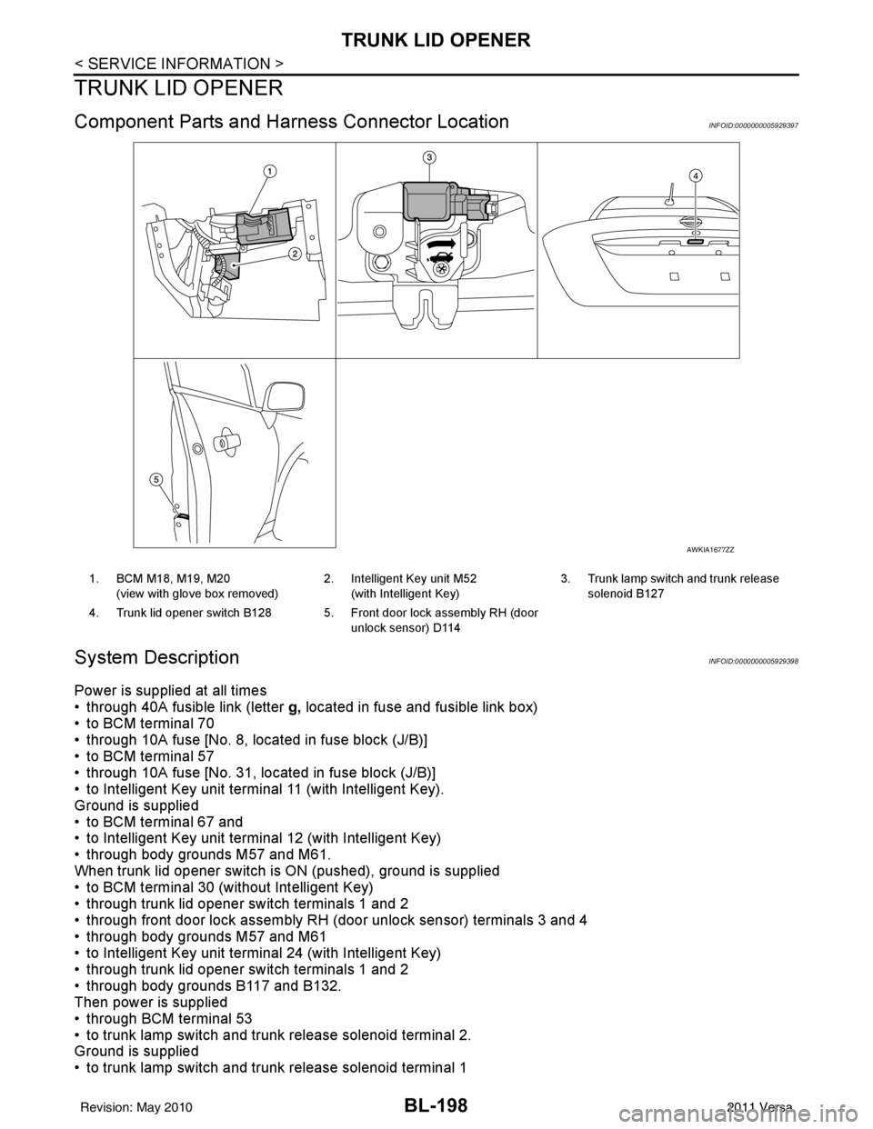
1. BCM M18, M19, M20
(view with glove box removed) 2. Intelligent Key unit M52
(with Intelligent Key) 3. Trunk lamp switch and trunk release
solenoid B127
4. Trunk lid opener switch B128 5. Front door lock assembly RH (door unlock sensor) D114
Revision: May 2010 2011 Versa
Page 718 of 3787
BL-208
< SERVICE INFORMATION >
TRUNK LID OPENER
CONSULT-III APPLICATION ITEMS
Data Monitor
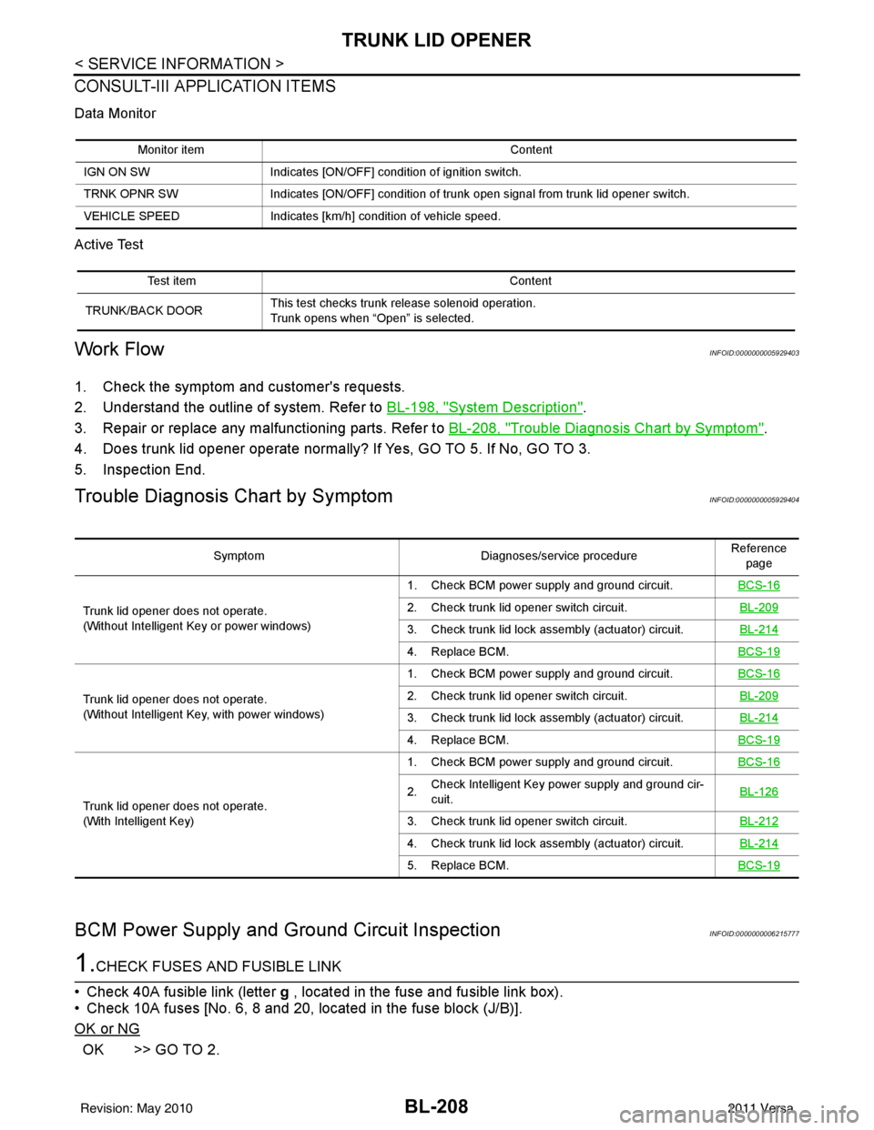
Active Test
Work FlowINFOID:0000000005929403
1. Check the symptom and customer's requests.
2. Understand the outline of system. Refer to BL-198, "
System Description".
3. Repair or replace any malfunctioning parts. Refer to BL-208, "
Trouble Diagnosis Chart by Symptom".
4. Does trunk lid opener operate normally? If Yes, GO TO 5. If No, GO TO 3.
5. Inspection End.
Trouble Diagnosis Chart by SymptomINFOID:0000000005929404
BCM Power Supply and Ground Circuit InspectionINFOID:0000000006215777
1.CHECK FUSES AND FUSIBLE LINK
• Check 40A fusible link (letter g , located in the fuse and fusible link box).
• Check 10A fuses [No. 6, 8 and 20, lo cated in the fuse block (J/B)].
OK or NG
OK >> GO TO 2.
Monitor item Content
IGN ON SW Indicates [ON/OFF] condition of ignition switch.
TRNK OPNR SW Indicates [ON/OFF] condition of trun k open signal from trunk lid opener switch.
VEHICLE SPEED Indicates [km/h] condition of vehicle speed.
Test item Content
TRUNK/BACK DOOR This test checks trunk release solenoid operation.
Trunk opens when “Open” is selected.
Symptom
Diagnoses/service procedureReference
page
Trunk lid opener does not operate.
(Without Intelligent Key or power windows) 1. Check BCM power supply and ground circuit.
BCS-16
2. Check trunk lid opener switch circuit. BL-209
3. Check trunk lid lock assembly (actuator) circuit.BL-214
4. Replace BCM.BCS-19
Trunk lid opener does not operate.
(Without Intelligent Key, with power windows)1. Check BCM power supply and ground circuit.
BCS-162. Check trunk lid opener switch circuit. BL-209
3. Check trunk lid lock assembly (actuator) circuit.BL-214
4. Replace BCM.BCS-19
Trunk lid opener does not operate.
(With Intelligent Key)1. Check BCM power supply and ground circuit.
BCS-16
2.Check Intelligent Key power supply and ground cir-
cuit.
BL-126
3. Check trunk lid opener switch circuit.
BL-212
4. Check trunk lid lock assembly (actuator) circuit.BL-214
5. Replace BCM.BCS-19
Revision: May 2010 2011 Versa
Page 719 of 3787
TRUNK LID OPENERBL-209
< SERVICE INFORMATION >
C
DE
F
G H
J
K L
M A
B
BL
N
O P
NG >> If fuse is blown, be sure to eliminate cause of malfunction before installing new fuse. Refer to PG-
4, "Schematic" .
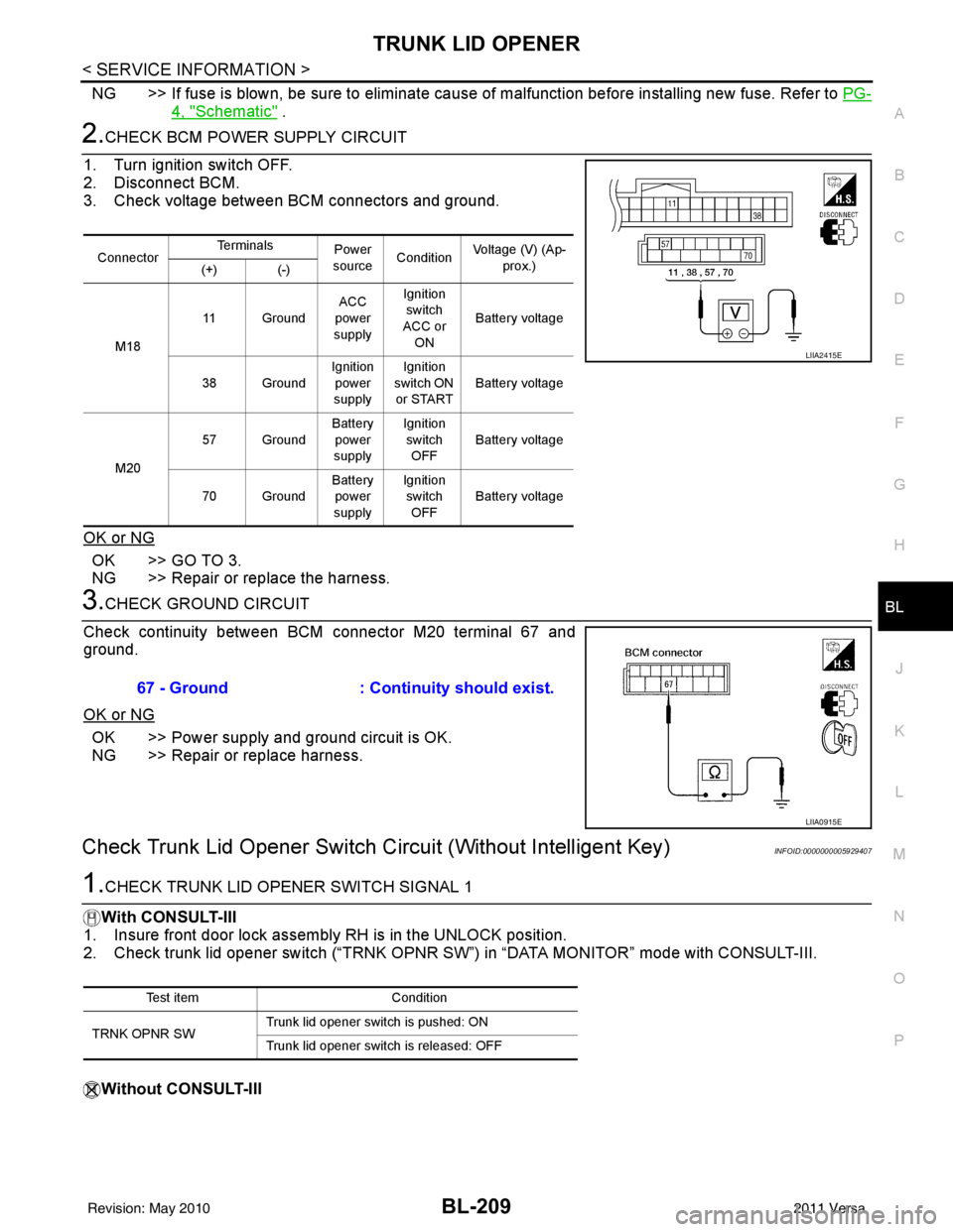
2.CHECK BCM POWER SUPPLY CIRCUIT
1. Turn ignition switch OFF.
2. Disconnect BCM.
3. Check voltage between BCM connectors and ground.
OK or NG
OK >> GO TO 3.
NG >> Repair or replace the harness.
3.CHECK GROUND CIRCUIT
Check continuity between BCM connector M20 terminal 67 and
ground.
OK or NG
OK >> Power supply and ground circuit is OK.
NG >> Repair or replace harness.
Check Trunk Lid Opener Switch Cir cuit (Without Intelligent Key)INFOID:0000000005929407
1.CHECK TRUNK LID OPENER SWITCH SIGNAL 1
With CONSULT-III
1. Insure front door lock assembly RH is in the UNLOCK position.
2. Check trunk lid opener switch (“TRNK OPNR SW”) in “DATA MONITOR” mode with CONSULT-III.
Without CONSULT-III
Connector Te r m i n a l s
Power
source Condition Voltage (V) (Ap-
prox.)
(+) (-)
M18 11 Ground
ACC
power
supply Ignition
switch
ACC or
ON Battery voltage
38 Ground Ignition
power
supply Ignition
switch ON or START Battery voltage
M20 57 Ground
Battery
power
supply Ignition
switch OFF Battery voltage
70 Ground Battery
power
supply Ignition
switch
OFF Battery voltage
LIIA2415E
67 - Ground
: Continuity should exist.
LIIA0915E
Test item Condition
TRNK OPNR SW Trunk lid opener switch is pushed: ON
Trunk lid opener switch is released: OFF
Revision: May 2010
2011 Versa
Page 720 of 3787
BL-210
< SERVICE INFORMATION >
TRUNK LID OPENER
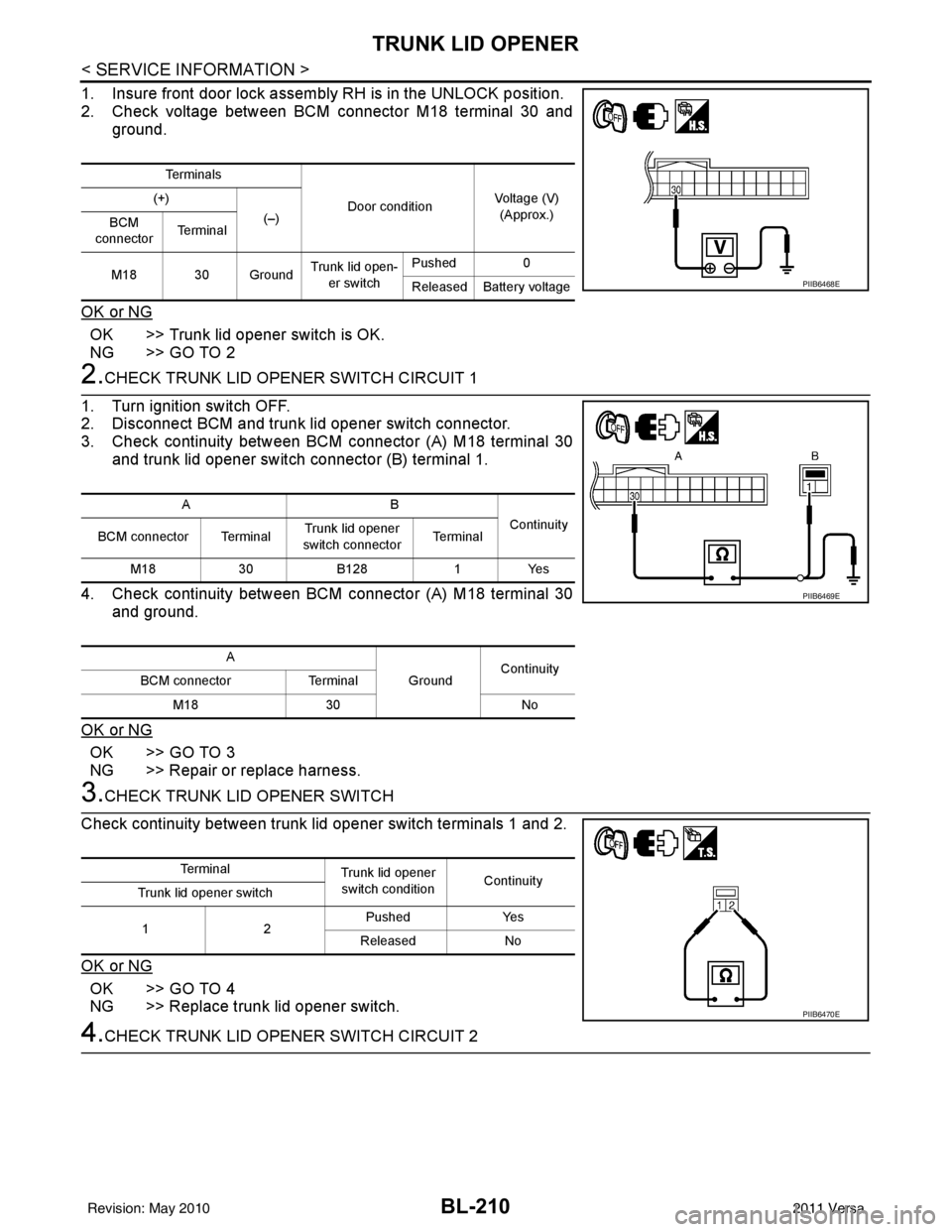
1. Insure front door lock assembly RH is in the UNLOCK position.
2. Check voltage between BCM connector M18 terminal 30 andground.
OK or NG
OK >> Trunk lid opener switch is OK.
NG >> GO TO 2
2.CHECK TRUNK LID OPENER SWITCH CIRCUIT 1
1. Turn ignition switch OFF.
2. Disconnect BCM and trunk lid opener switch connector.
3. Check continuity between BCM connector (A) M18 terminal 30 and trunk lid opener switch connector (B) terminal 1.
4. Check continuity between BCM connector (A) M18 terminal 30 and ground.
OK or NG
OK >> GO TO 3
NG >> Repair or replace harness.
3.CHECK TRUNK LID OPENER SWITCH
Check continuity between trunk lid opener switch terminals 1 and 2.
OK or NG
OK >> GO TO 4
NG >> Replace trunk lid opener switch.
4.CHECK TRUNK LID OPENER SWITCH CIRCUIT 2
Te r m i n a l s
Door conditionVoltage (V)
(Approx.)
(+)
(–)
BCM
connector Te r m i n a l
M18 30 Ground Trunk lid open-
er switch Pushed
0
Released Battery voltage
PIIB6468E
AB Continuity
BCM connector Terminal Trunk lid opener
switch connector Te r m i n a l
M18 30B128 1Yes
A GroundContinuity
BCM connector Terminal
M18 30 No
PIIB6469E
Te r m i n a l
Trunk lid opener
switch condition Continuity
Trunk lid opener switch
12 Pushed
Yes
Released No
PIIB6470E
Revision: May 2010 2011 Versa
Page 721 of 3787
TRUNK LID OPENERBL-211
< SERVICE INFORMATION >
C
DE
F
G H
J
K L
M A
B
BL
N
O P
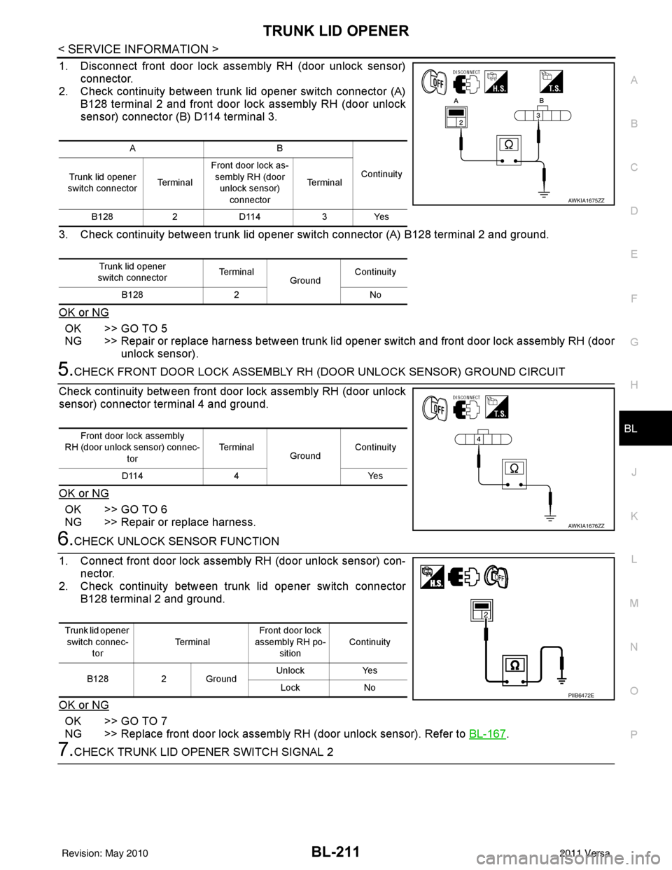
1. Disconnect front door lock asse mbly RH (door unlock sensor)
connector.
2. Check continuity between trunk lid opener switch connector (A)
B128 terminal 2 and front door lock assembly RH (door unlock
sensor) connector (B) D114 terminal 3.
3. Check continuity between trunk lid opener switch connector (A) B128 terminal 2 and ground.
OK or NG
OK >> GO TO 5
NG >> Repair or replace harness between trunk lid opener switch and front door lock assembly RH (door unlock sensor).
5.CHECK FRONT DOOR LOCK ASSEMBLY RH (DOOR UNLOCK SENSOR) GROUND CIRCUIT
Check continuity between front door lock assembly RH (door unlock
sensor) connector terminal 4 and ground.
OK or NG
OK >> GO TO 6
NG >> Repair or replace harness.
6.CHECK UNLOCK SENSOR FUNCTION
1. Connect front door lock assembly RH (door unlock sensor) con- nector.
2. Check continuity between trunk lid opener switch connector
B128 terminal 2 and ground.
OK or NG
OK >> GO TO 7
NG >> Replace front door lock assembly RH (door unlock sensor). Refer to BL-167
.
7.CHECK TRUNK LID OPENER SWITCH SIGNAL 2
AB
Continuity
Trunk lid opener
switch connector Te r m i n a lFront door lock as-
sembly RH (door unlock sensor) connector Te r m i n a l
B128 2D114 3Yes
Trunk lid opener
switch connector Te r m i n a l
GroundContinuity
B128 2 No
AWKIA1675ZZ
Front door lock assembly
RH (door unlock sensor) connec- tor Te r m i n a l
GroundContinuity
D114 4 Yes
AWKIA1676ZZ
Trunk lid opener
switch connec-
tor Te r m i n a l
Front door lock
assembly RH po-
sition Continuity
B128 2 Ground Unlock
Yes
Lock No
PIIB6472E
Revision: May 2010 2011 Versa
Page 726 of 3787
BL-216
< SERVICE INFORMATION >
FUEL FILLER LID OPENER
FUEL FILLER LID OPENER
Removal and Installation of Fuel Filler Lid OpenerINFOID:0000000005929410
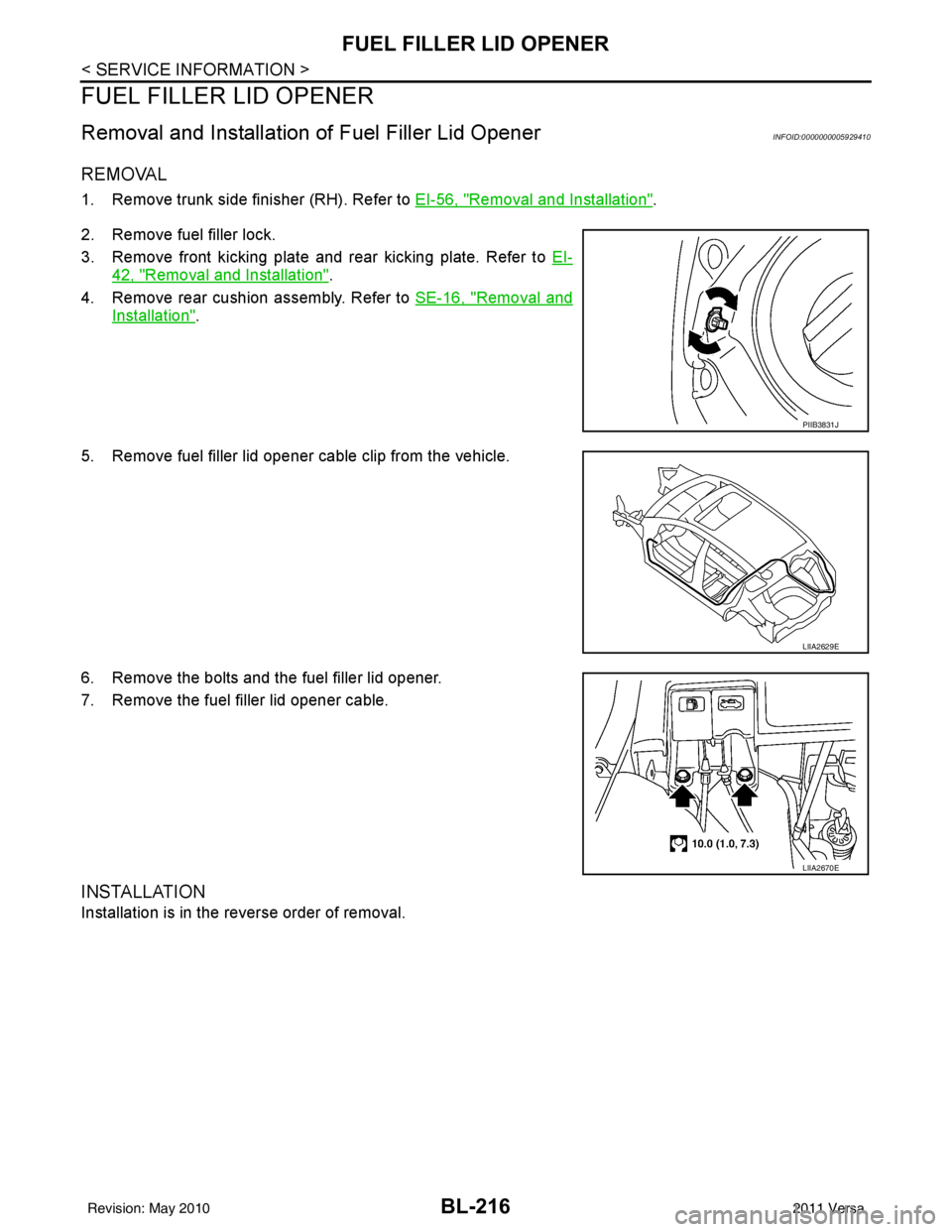
REMOVAL
1. Remove trunk side finisher (RH). Refer to EI-56, "Removal and Installation".
2. Remove fuel filler lock.
3. Remove front kicking plate and rear kicking plate. Refer to EI-
42, "Removal and Installation".
4. Remove rear cushion assembly. Refer to SE-16, "
Removal and
Installation".
5. Remove fuel filler lid opener cable clip from the vehicle.
6. Remove the bolts and the fuel filler lid opener.
7. Remove the fuel filler lid opener cable.
INSTALLATION
Installation is in the reverse order of removal.
PIIB3831J
LIIA2629E
LIIA2670E
Revision: May 2010 2011 Versa