ckp NISSAN TIIDA 2011 Service Repair Manual
[x] Cancel search | Manufacturer: NISSAN, Model Year: 2011, Model line: TIIDA, Model: NISSAN TIIDA 2011Pages: 3787, PDF Size: 78.35 MB
Page 1298 of 3787
EC-4
DTC Logic ..............................................................249
Wiring Diagram ......................................................250
Diagnosis Procedure .............................................250
Component Inspection ...........................................252
P0222, P0223 TP SENSOR .............................253
Description ........................................................... ..253
DTC Logic ..............................................................253
Wiring Diagram ......................................................254
Diagnosis Procedure .............................................254
Component Inspection ...........................................256
Special Repair Requirement ..................................256
P0300, P0301, P0302, P0303, P0304 MIS-
FIRE ................................................................ .
257
DTC Logic ............................................................ ..257
Diagnosis Procedure .............................................258
P0327, P0328 KS .............................................263
Description ........................................................... ..263
DTC Logic ..............................................................263
Wiring Diagram ......................................................264
Diagnosis Procedure .............................................264
Component Inspection ...........................................265
P0335 CKP SENSOR (POS) ...........................267
Description ........................................................... ..267
DTC Logic ..............................................................267
Wiring Diagram ......................................................268
Diagnosis Procedure .............................................269
Component Inspection ...........................................271
P0340 CMP SENSOR (PHASE) ......................272
Description ........................................................... ..272
DTC Logic ..............................................................272
Wiring Diagram ......................................................274
Diagnosis Procedure .............................................274
Component Inspection ...........................................276
P0420 THREE WAY CATALYST FUNCTION .277
DTC Logic ..............................................................277
Component Function Check ..................................278
Diagnosis Procedure .............................................279
P0441 EVAP CONTROL SYSTEM ..................282
DTC Logic ............................................................ ..282
Component Function Check ..................................283
Diagnosis Procedure .............................................284
Component Inspection (Drain filter) .......................287
P0442 EVAP CONTROL SYSTEM ..................288
DTC Logic ............................................................ ..288
Diagnosis Procedure .............................................289
Component Inspection (Fuel filler cap) ..................293
Component Inspection (Drain filter) .......................293
P0443 EVAP CANISTER PURGE VOLUME
CONTROL SOLENOID VALVE .......................
295
Description ........................................................... ..295
DTC Logic ..............................................................295
Wiring Diagram ......................................................297
Diagnosis Procedure ............................................ .297
Component Inspection ..........................................300
P0444, P0445 EVAP CANISTER PURGE
VOLUME CONTROL SOLENOID VALVE .......
301
Description ........................................................... .301
DTC Logic .............................................................301
Wiring Diagram .....................................................302
Diagnosis Procedure .............................................302
Component Inspection ..........................................304
P0447 EVAP CANISTER VENT CONTROL
VALVE ..............................................................
305
Description ........................................................... .305
DTC Logic .............................................................305
Wiring Diagram .....................................................306
Diagnosis Procedure .............................................306
Component Inspection ..........................................308
P0448 EVAP CANISTER VENT CONTROL
VALVE ..............................................................
310
Description ........................................................... .310
DTC Logic .............................................................310
Wiring Diagram .....................................................312
Diagnosis Procedure .............................................312
Component Inspection ..........................................314
P0451 EVAP CONTROL SYSTEM PRES-
SURE SENSOR ................................................
316
Description ........................................................... .316
DTC Logic .............................................................316
Diagnosis Procedure .............................................316
Component Inspection ..........................................318
P0452 EVAP CONTROL SYSTEM PRES-
SURE SENSOR ................................................
319
Description ........................................................... .319
DTC Logic .............................................................319
Wiring Diagram .....................................................321
Diagnosis Procedure .............................................321
Component Inspection ..........................................324
P0453 EVAP CONTROL SYSTEM PRES-
SURE SENSOR ................................................
326
Description ........................................................... .326
DTC Logic .............................................................326
Wiring Diagram .....................................................328
Diagnosis Procedure .............................................328
Component Inspection ..........................................332
P0455 EVAP CONTROL SYSTEM ..................333
DTC Logic .............................................................333
Diagnosis Procedure .............................................334
Component Inspection (Fuel filler cap) .................337
Component Inspection (Drain filter) ......................338
P0456 EVAP CONTROL SYSTEM ..................339
DTC Logic .............................................................339
Component Function Check .................................341
Diagnosis Procedure .............................................341
Revision: May 2010 2011 Versa
Page 1304 of 3787
EC-10
CONSULT-III Reference Value in Data Monitor
Mode .................................................................... ..
741
On Board Diagnosis Logic .....................................741
DTC Confirmation Procedure ................................741
Overall Function Check .........................................743
Wiring Diagram ......................................................744
Diagnosis Procedure .............................................745
Component Inspection ...........................................747
Removal and Installation .......................................749
DTC P014C, P014D A/F SENSOR 1 ...............750
Component Description ....................................... ..750
CONSULT-III Reference Value in Data Monitor
Mode .................................................................... ..
750
On Board Diagnosis Logic .....................................750
DTC Confirmation Procedure ................................750
Wiring Diagram ......................................................753
Diagnosis Procedure .............................................754
Removal and Installation .......................................757
DTC P0171 FUEL INJECTION SYSTEM
FUNCTION .......................................................
758
On Board Diagnosis Logic ................................... ..758
DTC Confirmation Procedure ................................758
Wiring Diagram ......................................................760
Diagnosis Procedure .............................................761
DTC P0172 FUEL INJECTION SYSTEM
FUNCTION .......................................................
764
On Board Diagnosis Logic ................................... ..764
DTC Confirmation Procedure ................................764
Wiring Diagram ......................................................766
Diagnosis Procedure .............................................767
DTC P0181 FTT SENSOR ...............................770
Component Description ....................................... ..770
On Board Diagnosis Logic .....................................770
DTC Confirmation Procedure ................................770
Wiring Diagram ......................................................771
Diagnosis Procedure .............................................771
Component Inspection ...........................................773
Removal and Installation .......................................773
DTC P0182, P0183 FTT SENSOR ..................774
Component Description ....................................... ..774
On Board Diagnosis Logic .....................................774
DTC Confirmation Procedure ................................774
Wiring Diagram ......................................................775
Diagnosis Procedure .............................................775
Component Inspection ...........................................777
Removal and Installation .......................................777
DTC P0222, P0223 TP SENSOR ....................778
Component Description ....................................... ..778
CONSULT-III Reference Value in Data Monitor
Mode .................................................................... ..
778
On Board Diagnosis Logic .....................................778
DTC Confirmation Procedure ................................778
Wiring Diagram ......................................................779
Diagnosis Procedure .............................................780
Component Inspection ......................................... .782
Removal and Installation .......................................782
DTC P0300 - P0304 MULTIPLE CYLINDER
MISFIRE, NO. 1 - 4 CYLINDER MISFIRE ...... ..
783
On Board Diagnosis Logic ................................... .783
DTC Confirmation Procedure ................................783
Diagnosis Procedure .............................................784
DTC P0327, P0328 KS .....................................789
Component Description ....................................... .789
On Board Diagnosis Logic ....................................789
DTC Confirmation Procedure ................................789
Wiring Diagram .....................................................790
Diagnosis Procedure .............................................791
Component Inspection ..........................................792
Removal and Installation .......................................792
DTC P0335 CKP SENSOR (POS) .................. ..793
Component Description ....................................... .793
CONSULT-III Reference Value in Data Monitor
Mode .................................................................... .
793
On Board Diagnosis Logic ....................................793
DTC Confirmation Procedure ................................793
Wiring Diagram .....................................................794
Diagnosis Procedure .............................................795
Component Inspection ..........................................798
Removal and Installation .......................................798
DTC P0340 CMP SENSOR (PHASE) ............ ..799
Component Description ....................................... .799
CONSULT-III Reference Value in Data Monitor
Mode .................................................................... .
799
On Board Diagnosis Logic ....................................799
DTC Confirmation Procedure ................................799
Wiring Diagram .....................................................800
Diagnosis Procedure .............................................801
Component Inspection ..........................................803
Removal and Installation .......................................804
DTC P0420 THREE WAY CATALYST FUNC-
TION ................................................................ ..
805
On Board Diagnosis Logic ................................... .805
DTC Confirmation Procedure ................................805
Overall Function Check .........................................805
Diagnosis Procedure .............................................806
DTC P0441 EVAP CONTROL SYSTEM ..........810
System Description .............................................. .810
On Board Diagnosis Logic ....................................810
DTC Confirmation Procedure ................................810
Overall Function Check .........................................811
Diagnosis Procedure .............................................811
Component Inspection ..........................................814
DTC P0442 EVAP CONTROL SYSTEM ..........815
On Board Diagnosis Logic ................................... .815
DTC Confirmation Procedure ................................816
Diagnosis Procedure .............................................816
Component Inspection ..........................................821
Revision: May 2010 2011 Versa
Page 1551 of 3787
P0300, P0301, P0302, P0303, P0304 MISFIRE
EC-257
< COMPONENT DIAGNOSIS > [HR16DE]
C
D
E
F
G H
I
J
K L
M A
EC
NP
O
P0300, P0301, P0302, P0303, P0304 MISFIRE
DTC LogicINFOID:0000000005929932
DTC DETECTION LOGIC
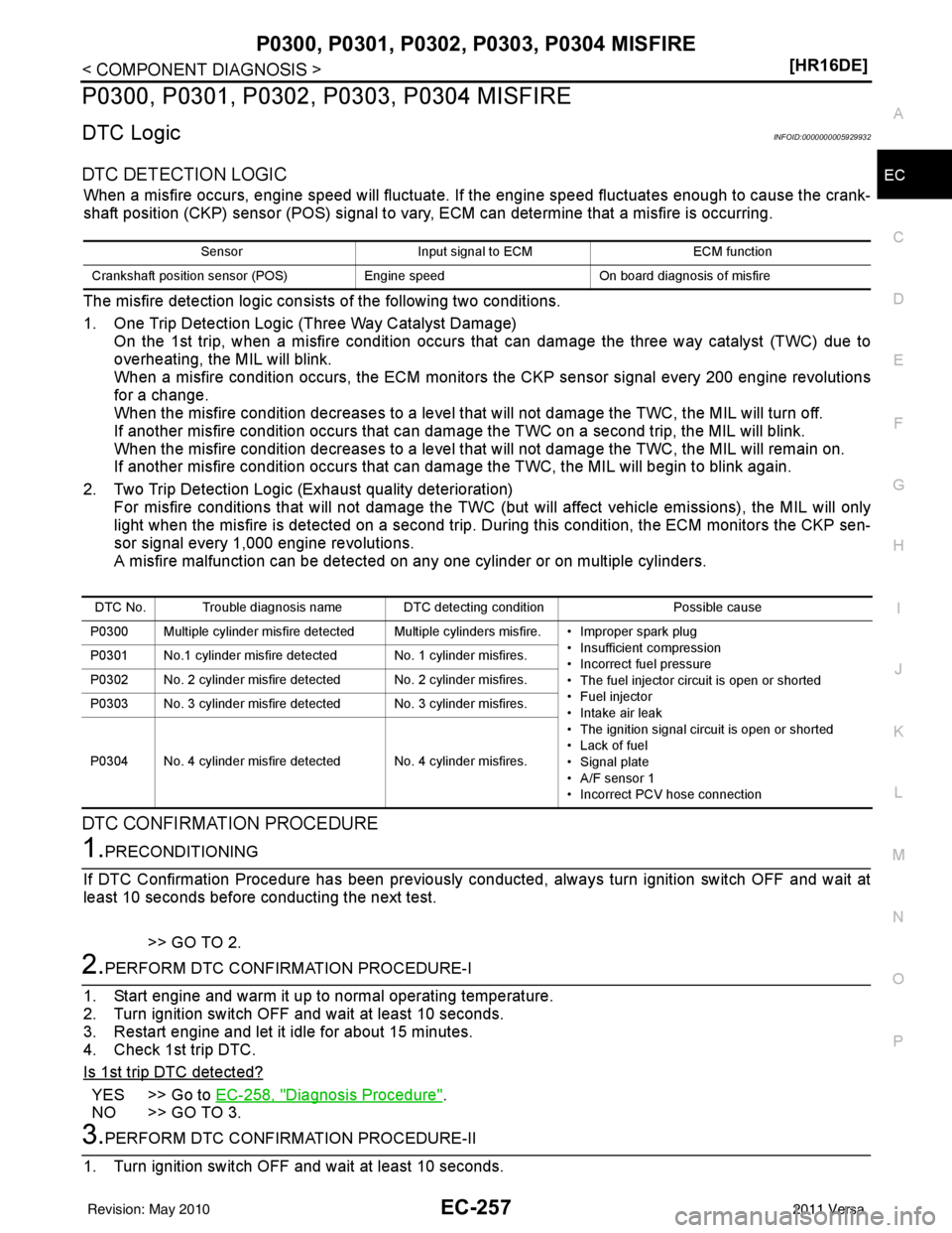
When a misfire occurs, engine speed will fluctuate. If the engine speed fluctuates
enough to cause the crank-
shaft position (CKP) sensor (POS) signal to vary, ECM can determine that a misfire is occurring.
The misfire detection logic consists of the following two conditions.
1. One Trip Detection Logic (Three Way Catalyst Damage)
On the 1st trip, when a misfire condition occurs that can damage the three way catalyst (TWC) due to
overheating, the MIL will blink.
When a misfire condition occurs, the ECM monitors the CKP sensor signal every 200 engine revolutions
for a change.
When the misfire condition decreases to a level t hat will not damage the TWC, the MIL will turn off.
If another misfire condition occurs that can damage the TWC on a second trip, the MIL will blink.
When the misfire condition decreases to a level t hat will not damage the TWC, the MIL will remain on.
If another misfire condition occurs that can damage the TWC, the MIL will begin to blink again.
2. Two Trip Detection Logic (Exhaust quality deterioration) For misfire conditions that will not damage the TWC (but will affect vehicle emissions), the MIL will only
light when the misfire is detected on a second trip. Du ring this condition, the ECM monitors the CKP sen-
sor signal every 1,000 engine revolutions.
A misfire malfunction can be detected on any one cylinder or on multiple cylinders.
DTC CONFIRMATION PROCEDURE
1.PRECONDITIONING
If DTC Confirmation Procedure has been previously conducted, always turn ignition switch OFF and wait at
least 10 seconds before conducting the next test.
>> GO TO 2.
2.PERFORM DTC CONFIRMATION PROCEDURE-I
1. Start engine and warm it up to normal operating temperature.
2. Turn ignition switch OFF and wait at least 10 seconds.
3. Restart engine and let it idle for about 15 minutes.
4. Check 1st trip DTC.
Is 1st trip DTC detected?
YES >> Go to EC-258, "Diagnosis Procedure".
NO >> GO TO 3.
3.PERFORM DTC CONFIRMATION PROCEDURE-II
1. Turn ignition switch OFF and wait at least 10 seconds.
Sensor Input signal to ECM ECM function
Crankshaft position sensor (POS) Engine speedOn board diagnosis of misfire
DTC No. Trouble diagnosis name DTC detecting condition Possible cause
P0300 Multiple cylinder misfire detected Multiple cylinders misfire. • Improper spark plug • Insufficient compression
• Incorrect fuel pressure
• The fuel injector circuit is open or shorted
• Fuel injector
• Intake air leak
• The ignition signal circuit is open or shorted
• Lack of fuel
• Signal plate
• A/F sensor 1
• Incorrect PCV hose connection
P0301 No.1 cylinder misfire detected No. 1 cylinder misfires.
P0302 No. 2 cylinder misfire detected No. 2 cylinder misfires.
P0303 No. 3 cylinder misfire detected No. 3 cylinder misfires.
P0304 No. 4 cylinder misfire detected No. 4 cylinder misfires.
Revision: May 2010
2011 Versa
Page 1561 of 3787
P0335 CKP SENSOR (POS)EC-267
< COMPONENT DIAGNOSIS > [HR16DE]
C
D
E
F
G H
I
J
K L
M A
EC
NP
O
P0335 CKP SENSOR (POS)
DescriptionINFOID:0000000005929939
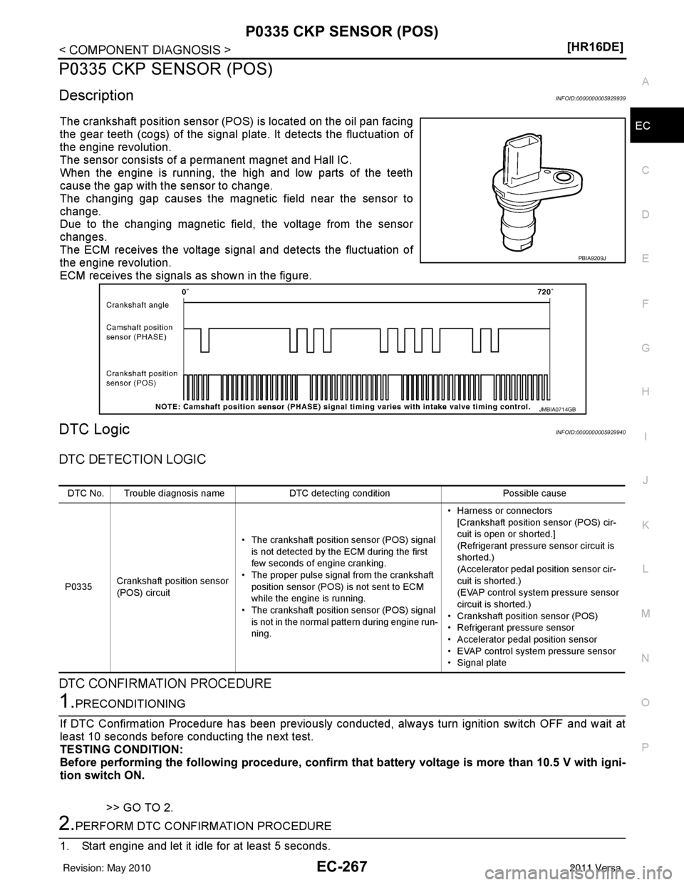
The crankshaft position sensor (POS
) is located on the oil pan facing
the gear teeth (cogs) of the signal pl ate. It detects the fluctuation of
the engine revolution.
The sensor consists of a permanent magnet and Hall IC.
When the engine is running, the high and low parts of the teeth
cause the gap with the sensor to change.
The changing gap causes the magnetic field near the sensor to
change.
Due to the changing magnetic fiel d, the voltage from the sensor
changes.
The ECM receives the voltage signal and detects the fluctuation of
the engine revolution.
ECM receives the signals as shown in the figure.
DTC LogicINFOID:0000000005929940
DTC DETECTION LOGIC
DTC CONFIRMATION PROCEDURE
1.PRECONDITIONING
If DTC Confirmation Procedure has been previously conducted, always turn ignition switch OFF and wait at
least 10 seconds before conducting the next test.
TESTING CONDITION:
Before performing the follo wing procedure, confirm that battery vo ltage is more than 10.5 V with igni-
tion switch ON.
>> GO TO 2.
2.PERFORM DTC CONFIRMATION PROCEDURE
1. Start engine and let it idle for at least 5 seconds.
PBIA9209J
JMBIA0714GB
DTC No. Trouble diagnosis name DTC detecting conditionPossible cause
P0335 Crankshaft position sensor
(POS) circuit • The crankshaft position sensor (POS) signal
is not detected by the ECM during the first
few seconds of engine cranking.
• The proper pulse signal from the crankshaft position sensor (POS) is not sent to ECM
while the engine is running.
• The crankshaft position sensor (POS) signal is not in the normal pattern during engine run-
ning. • Harness or connectors
[Crankshaft position sensor (POS) cir-
cuit is open or shorted.]
(Refrigerant pressure sensor circuit is
shorted.)
(Accelerator pedal position sensor cir-
cuit is shorted.)
(EVAP control system pressure sensor
circuit is shorted.)
• Crankshaft position sensor (POS)
• Refrigerant pressure sensor
• Accelerator pedal position sensor
• EVAP control system pressure sensor
• Signal plate
Revision: May 2010 2011 Versa
Page 1562 of 3787
EC-268
< COMPONENT DIAGNOSIS >[HR16DE]
P0335 CKP SENSOR (POS)
If engine does not start, crank
engine for at least 2 seconds.
2. Check 1st trip DTC.
Is 1st trip DTC detected?
YES >> Go to EC-269, "Diagnosis Procedure".
NO >> INSPECTION END
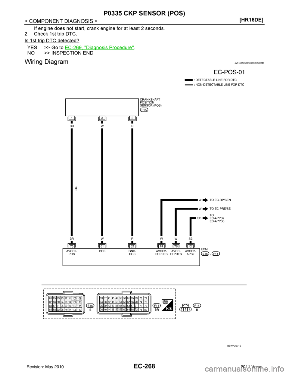
Wiring DiagramINFOID:0000000005929941
BBWA3071E
Revision: May 2010 2011 Versa
Page 1563 of 3787
P0335 CKP SENSOR (POS)EC-269
< COMPONENT DIAGNOSIS > [HR16DE]
C
D
E
F
G H
I
J
K L
M A
EC
NP
O
Diagnosis ProcedureINFOID:0000000005929942
1.CHECK GROUND CONNECTION
1. Turn ignition switch OFF.
2. Check ground connections E15, E24. Refer to EC-127, "
Ground Inspection".
Is the inspection result normal?
YES >> GO TO 2.
NO >> Repair or replace ground connection.
2.CHECK CRANKSHAFT POSITION (CKP) SEN SOR (POS) POWER SUPPLY CIRCUIT-I
1. Disconnect crankshaft position (CKP) sensor (POS) harness connector.
2. Turn ignition switch ON.
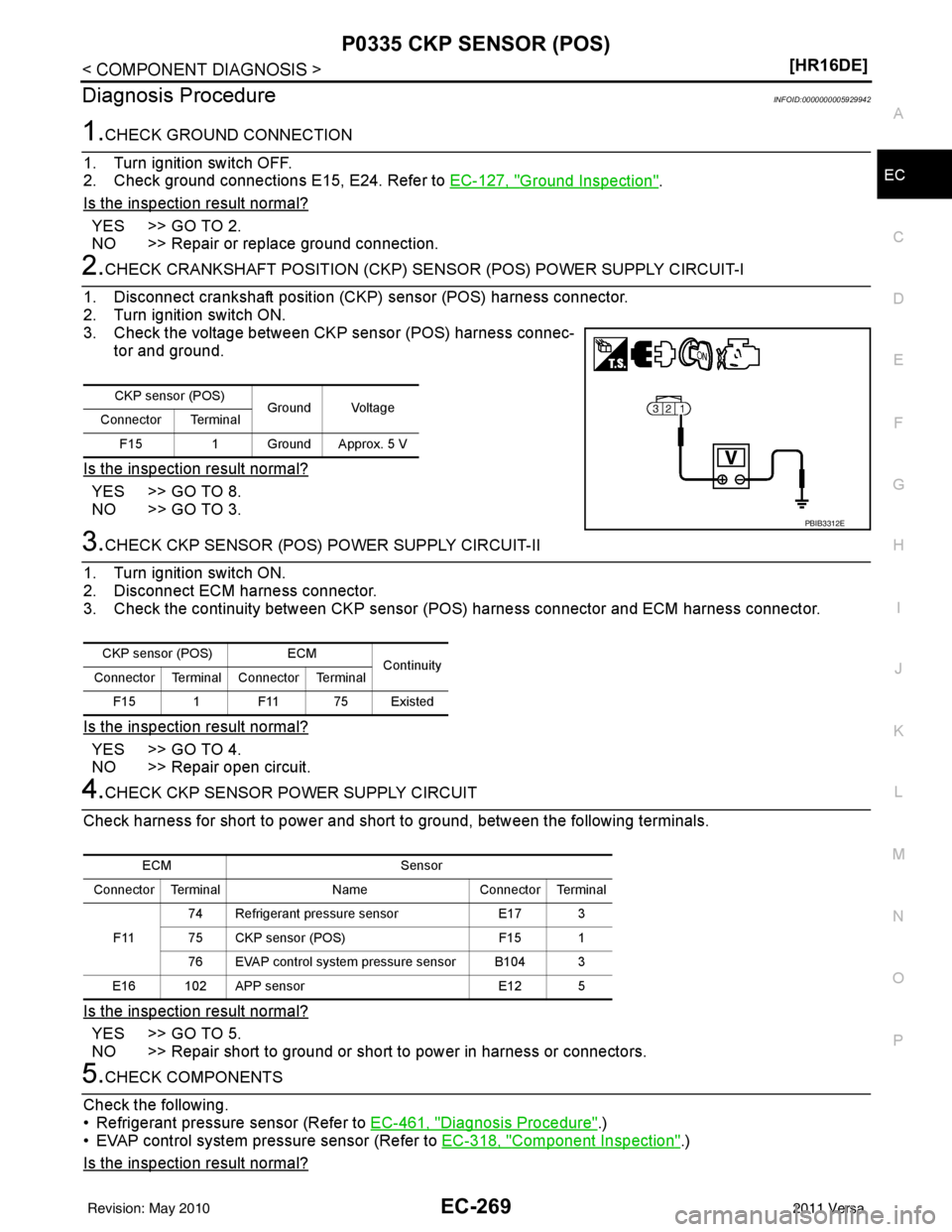
3. Check the voltage between CKP sensor (POS) harness connec- tor and ground.
Is the inspection result normal?
YES >> GO TO 8.
NO >> GO TO 3.
3.CHECK CKP SENSOR (POS) POWER SUPPLY CIRCUIT-II
1. Turn ignition switch ON.
2. Disconnect ECM harness connector.
3. Check the continuity between CKP sensor (POS) harness connector and ECM harness connector.
Is the inspection result normal?
YES >> GO TO 4.
NO >> Repair open circuit.
4.CHECK CKP SENSOR POWER SUPPLY CIRCUIT
Check harness for short to power and short to ground, between the following terminals.
Is the inspection result normal?
YES >> GO TO 5.
NO >> Repair short to ground or short to power in harness or connectors.
5.CHECK COMPONENTS
Check the following.
• Refrigerant pressure sensor (Refer to EC-461, "
Diagnosis Procedure".)
• EVAP control system pressure sensor (Refer to EC-318, "
Component Inspection".)
Is the inspection result normal?
CKP sensor (POS) Ground Voltage
Connector Terminal
F15 1 Ground Approx. 5 V
PBIB3312E
CKP sensor (POS) ECM
Continuity
Connector Terminal Connector Terminal
F15 1 F11 75 Existed
ECM Sensor
Connector Terminal NameConnector Terminal
F11 74 Refrigerant pressure sensor
E17 3
75 CKP sensor (POS) F15 1
76 EVAP control system pressure sensor B104 3
E16 102 APP sensor E12 5
Revision: May 2010 2011 Versa
Page 1564 of 3787
EC-270
< COMPONENT DIAGNOSIS >[HR16DE]
P0335 CKP SENSOR (POS)
YES >> GO TO 6.
NO >> Replace malfunctioning components.
6.CHECK APP SENSOR
Refer to EC-405, "
Component Inspection".
Is the inspection result normal?
YES >> GO TO 12.
NO >> GO TO 7.
7.REPLACE ACCELERATOR PEDAL ASSEMBLY
1. Replace accelerator pedal assembly. Refer to ACC-4, "
Removal and Installation".
2. Perform EC-405, "
Special Repair Requirement".
>> INSPECTION END
8.CHECK CKP SENSOR (POS) GRO UND CIRCUIT FOR OPEN AND SHORT
1. Turn ignition switch OFF.
2. Check the continuity between CKP sensor (POS) harness connector and ECM harness connector.
3. Also check harness for short to ground and short to power.
Is the inspection result normal?
YES >> GO TO 9.
NO >> Repair open circuit or short to ground or short to power in harness or connectors.
9.CHECK CKP SENSOR (POS) INPUT SI GNAL CIRCUIT FOR OPEN AND SHORT
1. Disconnect ECM harness connector.
2. Check the continuity between CKP sensor (POS) harness connector and ECM harness connector.
3. Also check harness for short to ground and short to power.
Is the inspection result normal?
YES >> GO TO 10.
NO >> Repair open circuit or short to ground or short to power in harness or connectors.
10.CHECK CRANKSHAFT POSI TION SENSOR (POS)
Refer to EC-271, "
Component Inspection".
Is the inspection result normal?
YES >> GO TO 11.
NO >> Replace crankshaft position sensor (POS). Refer to EM-89, "
Exploded View".
11 .CHECK GEAR TOOTH
Visually check for chipping signal plate gear tooth.
Is the inspection result normal?
YES >> GO TO 12.
NO >> Replace the signal plate. Refer to EM-89, "
Exploded View".
12.CHECK INTERMITTENT INCIDENT
Refer to EC-122, "
Diagnosis Procedure".
CKP sensor (POS) ECM
Continuity
Connector Terminal Connector Terminal
F15 2 F11 62 Existed
CKP sensor (POS) ECM
Continuity
Connector Terminal Connector Terminal
F15 3 F11 61 Existed
Revision: May 2010 2011 Versa
Page 1565 of 3787
P0335 CKP SENSOR (POS)EC-271
< COMPONENT DIAGNOSIS > [HR16DE]
C
D
E
F
G H
I
J
K L
M A
EC
NP
O
>> INSPECTION END
Component InspectionINFOID:0000000005929943
1.CHECK CRANKSHAFT POSI
TION SENSOR (POS)-I
1. Turn ignition switch OFF.
2. Loosen the fixing bolt of the sensor.
3. Disconnect crankshaft position sensor (POS) harness connector.
4. Remove the sensor.
5. Visually check the sensor for chipping.
Is the inspection result normal?
YES >> GO TO 2.
NO >> Replace crankshaft position sensor (POS). Refer to EM-
89, "Exploded View".
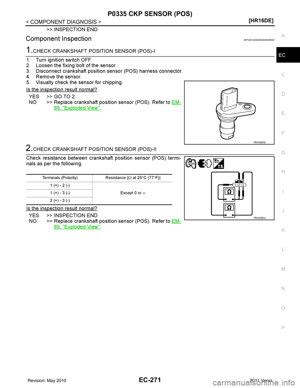
2.CHECK CRANKSHAFT POSITION SENSOR (POS)-II
Check resistance between crankshaft position sensor (POS) termi-
nals as per the following.
Is the inspection result normal?
YES >> INSPECTION END
NO >> Replace crankshaft position sensor (POS). Refer to EM-
89, "Exploded View".
PBIA9209J
Terminals (Polarity)Resistance [Ω at 25 °C (77 °F)]
1 (+) - 2 (-) Except 0 or ∞
1 (+) - 3 (-)
2 (+) - 3 (-)
PBIA9584J
Revision: May 2010 2011 Versa
Page 1611 of 3787
P0451 EVAP CONTROL SYSTEM PRESSURE SENSOREC-317
< COMPONENT DIAGNOSIS > [HR16DE]
C
D
E
F
G H
I
J
K L
M A
EC
NP
O
YES >> GO TO 2.
NO >> Repair or replace ground connection.
2.CHECK EVAP CONTROL SYS
TEM PRESSURE SENSOR CONNECTOR FOR WATER
1. Disconnect EVAP control system pressure sensor harness connector.
2. Check sensor harness connector for water.
Is the inspection result normal?
YES >> GO TO 3.
NO >> Repair or replace harness connector.
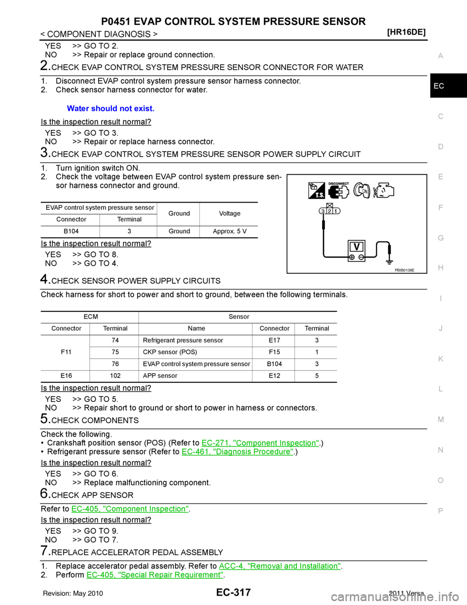
3.CHECK EVAP CONTROL SYS TEM PRESSURE SENSOR POWER SUPPLY CIRCUIT
1. Turn ignition switch ON.
2. Check the voltage between EVAP control system pressure sen- sor harness connector and ground.
Is the inspection result normal?
YES >> GO TO 8.
NO >> GO TO 4.
4.CHECK SENSOR POWER SUPPLY CIRCUITS
Check harness for short to power and short to ground, between the following terminals.
Is the inspection result normal?
YES >> GO TO 5.
NO >> Repair short to ground or short to power in harness or connectors.
5.CHECK COMPONENTS
Check the following.
• Crankshaft position sensor (POS) (Refer to EC-271, "
Component Inspection".)
• Refrigerant pressure sensor (Refer to EC-461, "
Diagnosis Procedure".)
Is the inspection result normal?
YES >> GO TO 6.
NO >> Replace malfunctioning component.
6.CHECK APP SENSOR
Refer to EC-405, "
Component Inspection".
Is the inspection result normal?
YES >> GO TO 9.
NO >> GO TO 7.
7.REPLACE ACCELERATOR PEDAL ASSEMBLY
1. Replace accelerator pedal assembly. Refer to ACC-4, "
Removal and Installation".
2. Perform EC-405, "
Special Repair Requirement".
Water should not exist.
EVAP control system pressure sensor
Ground Voltage
Connector Terminal
B104 3Ground Approx. 5 V
PBIB0138E
ECM Sensor
Connector Terminal NameConnector Terminal
F11 74 Refrigerant pressure sensor
E173
75 CKP sensor (POS) F151
76 EVAP control system pressure sensor B104 3
E16 102 APP sensor E125
Revision: May 2010 2011 Versa
Page 1617 of 3787
P0452 EVAP CONTROL SYSTEM PRESSURE SENSOREC-323
< COMPONENT DIAGNOSIS > [HR16DE]
C
D
E
F
G H
I
J
K L
M A
EC
NP
O
Is the inspection result normal?
YES >> GO TO 7.
NO >> Repair short to ground or short to power in harness or connectors.
7.CHECK COMPONENTS
Check the following.
• Crankshaft position sensor (POS) (Refer to EC-271, "
Component Inspection".)
• Refrigerant pressure sensor (Refer to EC-461, "
Diagnosis Procedure".)
Is the inspection result normal?
YES >> GO TO 8.
NO >> Replace malfunctioning component.
8.CHECK APP SENSOR
Refer to EC-405, "
Component Inspection".
Is the inspection result normal?
YES >> GO TO 10.
NO >> GO TO 9.
9.REPLACE ACCELERATOR PEDAL ASSEMBLY
1. Replace accelerator pedal assembly. Refer to ACC-4, "
Removal and Installation".
2. Perform EC-405, "
Special Repair Requirement".
>> INSPECTION END
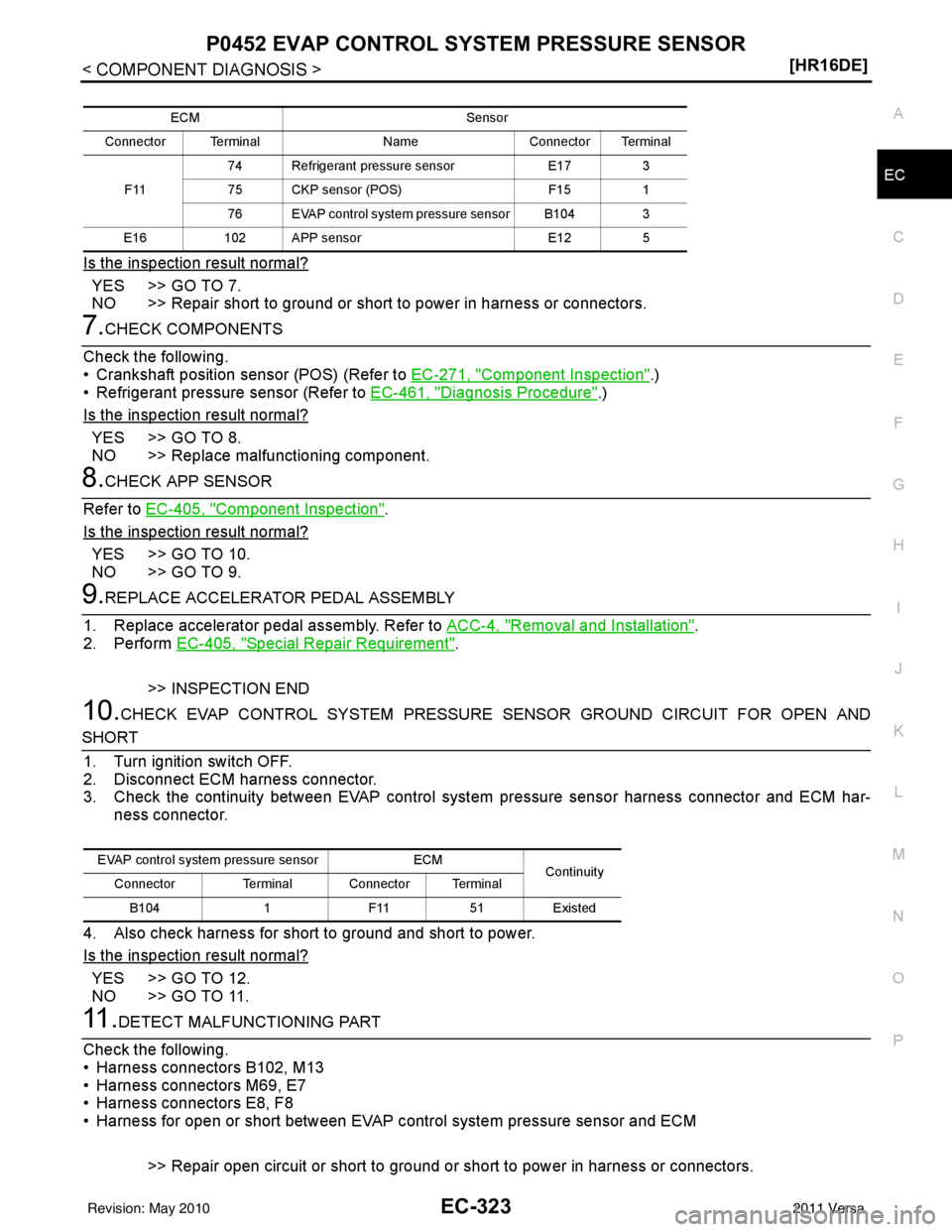
10.CHECK EVAP CONTROL SYSTEM PRESSURE SENSOR GROUND CIRCUIT FOR OPEN AND
SHORT
1. Turn ignition switch OFF.
2. Disconnect ECM harness connector.
3. Check the continuity between EVAP control syst em pressure sensor harness connector and ECM har-
ness connector.
4. Also check harness for short to ground and short to power.
Is the inspection result normal?
YES >> GO TO 12.
NO >> GO TO 11.
11 .DETECT MALFUNCTIONING PART
Check the following.
• Harness connectors B102, M13
• Harness connectors M69, E7
• Harness connectors E8, F8
• Harness for open or short between EVAP c ontrol system pressure sensor and ECM
>> Repair open circuit or short to ground or short to power in harness or connectors.
ECM Sensor
Connector Terminal NameConnector Terminal
F11 74 Refrigerant pressure sensor
E173
75 CKP sensor (POS) F151
76 EVAP control system pressure sensor B104 3
E16 102 APP sensor E125
EVAP control system pressure sensor ECM
Continuity
Connector Terminal Connector Terminal
B104 1F1151Existed
Revision: May 2010 2011 Versa