parking brake NISSAN TIIDA 2011 Service Repair Manual
[x] Cancel search | Manufacturer: NISSAN, Model Year: 2011, Model line: TIIDA, Model: NISSAN TIIDA 2011Pages: 3787, PDF Size: 78.35 MB
Page 1 of 3787
-1
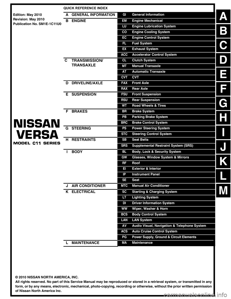
QUICK REFERENCE INDEX
AGENERAL INFORMATIONGIGeneral Information
BENGINEEMEngine Mechanical
LUEngine Lubrication System
COEngine Cooling System
ECEngine Control System
FLFuel System
EXExhaust System
ACCAccelerator Control System
CTRANSMISSION/
TRANSAXLECLClutch System
MTManual Transaxle
ATAutomatic Transaxle
CVTCVT
DDRIVELINE/AXLEFAXFront Axle
RAXRear Axle
ESUSPENSIONFSUFront Suspension
RSURear Suspension
WTRoad Wheels & Tires
FBRAKESBRBrake System
PBParking Brake System
BRCBrake Control System
GSTEERINGPSPower Steering System
STCSteering Control System
HRESTRAINTSSBSeat Belts
SRSSupplemental Restraint System (SRS)
IBODYBLBody, Lock & Security System
GWGlasses, Window System & Mirrors
RFRoof
EIExterior & Interior
IPInstrument Panel
SESeat
JAIR CONDITIONERMTCManual Air Conditioner
KELECTRICALSCStarting & Charging System
LTLighting System
DIDriver Information System
WWWiper, Washer & Horn
BCSBody Control System
LANLAN System
AVAudio Visual, Navigation & Telephone System
ACSAuto Cruise Control System
PGPower Supply, Ground & Circuit Elements
LMAINTENANCEMAMaintenance
Edition: May 2010
Revision: May 2010
Publication No. SM1E-1C11U0
B
D
© 2010 NISSAN NORTH AMERICA, INC.
All rights reserved. No part of this Service Manual may be reproduced or stored in a retrieval system, or transmitted in any
form, or by any means, electronic, mechanical, photo-copying, recording or otherwise, without the prior written permission
of Nissan North America Inc.
A
C
E
F
G
H
I
J
K
L
M
Page 34 of 3787
A/T FLUIDAT-17
< SERVICE INFORMATION >
DE
F
G H
I
J
K L
M A
B
AT
N
O P
A/T FLUID
Checking A/T FluidINFOID:0000000005928070
1. Warm up engine.
2. Check for A/T fluid leakage.
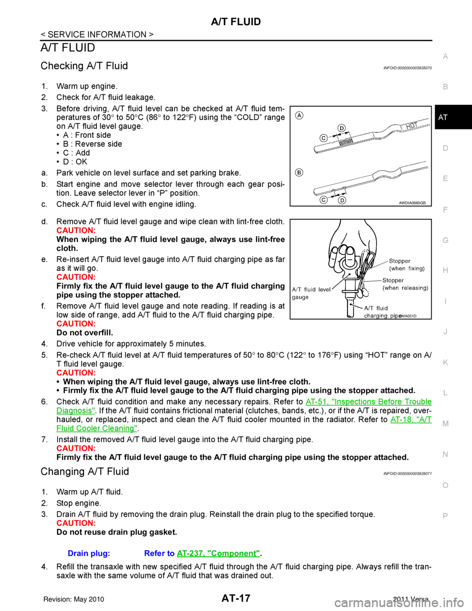
3. Before driving, A/T fluid level can be checked at A/T fluid tem- peratures of 30° to 50°C (86° to 122° F) using the “COLD” range
on A/T fluid level gauge.
• A : Front side
• B : Reverse side
•C : Add
• D : OK
a. Park vehicle on level surface and set parking brake.
b. Start engine and move selector lever through each gear posi- tion. Leave selector lever in “P” position.
c. Check A/T fluid level with engine idling.
d. Remove A/T fluid level gauge and wipe clean with lint-free cloth. CAUTION:
When wiping the A/T fluid l evel gauge, always use lint-free
cloth.
e. Re-insert A/T fluid level gauge into A/T fluid charging pipe as far as it will go.
CAUTION:
Firmly fix the A/T fluid level ga uge to the A/T fluid charging
pipe using the stopper attached.
f. Remove A/T fluid level gauge and note reading. If reading is at low side of range, add A/T fluid to the A/T fluid charging pipe.
CAUTION:
Do not overfill.
4. Drive vehicle for approximately 5 minutes.
5. Re-check A/T fluid level at A/T fluid temperatures of 50° to 80 °C (122° to 176°F) using “HOT” range on A/
T fluid level gauge.
CAUTION:
• When wiping the A/T fluid level gauge, always use lint-free cloth.
• Firmly fix the A/T fluid level ga uge to the A/T fluid charging pipe using the stopper attached.
6. Check A/T fluid condition and make any necessary repairs. Refer to AT-51, "
Inspections Before Trouble
Diagnosis". If the A/T fluid contains frictional material (clutches, bands, etc.), or if the A/T is repaired, over-
hauled, or replaced, inspect and clean the A/T fluid cooler mounted in the radiator. Refer to AT-18, "
A/T
Fluid Cooler Cleaning".
7. Install the removed A/T fluid level gauge into the A/T fluid charging pipe. CAUTION:
Firmly fix the A/T fluid level gaug e to the A/T fluid charging pipe using the stopper attached.
Changing A/T FluidINFOID:0000000005928071
1. Warm up A/T fluid.
2. Stop engine.
3. Drain A/T fluid by removing the drain plug. Re install the drain plug to the specified torque.
CAUTION:
Do not reuse drain plug gasket.
4. Refill the transaxle with new specified A/T fluid through the A/T fluid charging pipe. Always refill the tran- saxle with the same volume of A/T fluid that was drained out.
AWDIA0660GB
SMA051D
Drain plug: Refer to AT-237, "Component".
Revision: May 2010 2011 Versa
Page 40 of 3787
A/T CONTROL SYSTEMAT-23
< SERVICE INFORMATION >
DE
F
G H
I
J
K L
M A
B
AT
N
O P
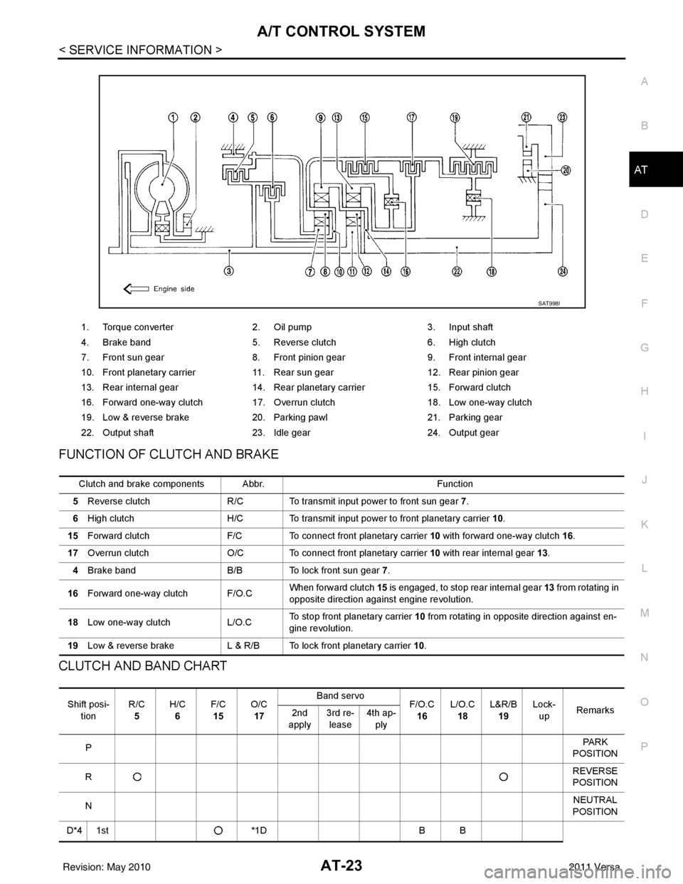
FUNCTION OF CLUTCH AND BRAKE
CLUTCH AND BAND CHART
1. Torque converter 2. Oil pump 3. Input shaft
4. Brake band 5. Reverse clutch 6. High clutch
7. Front sun gear 8. Front pinion gear 9. Front internal gear
10. Front planetary carrier 11. Rear sun gear 12. Rear pinion gear
13. Rear internal gear 14. Rear planetary carrier 15. Forward clutch
16. Forward one-way clutch 17. Overrun clutch 18. Low one-way clutch
19. Low & reverse brake 20. Parking pawl 21. Parking gear
22. Output shaft 23. Idle gear 24. Output gear
SAT998I
Clutch and brake components Abbr. Function
5 Reverse clutch R/C To transmit input power to front sun gear 7 .
6 High clutch H/C To transmit input power to front planetary carrier 10.
15 Forward clutch F/C To connect front planetary carrier 10 with forward one-way clutch 16.
17 Overrun clutch O/C To connect front planetary carrier 10 with rear internal gear 13 .
4 Brake band B/B To lock front sun gear 7.
16 Forward one-way clutch F/O.C When forward clutch 15
is engaged, to stop rear internal gear 13 from rotating in
opposite direction against engine revolution.
18 Low one-way clutch L/O.CTo stop front planetary carrier
10 from rotating in opposite direction against en-
gine revolution.
19 Low & reverse brake L & R/B To lock front planetary carrier 10.
Shift posi-
tion R/C
5 H/C
6 F/C
15 O/C
17 Band servo
F/O.C
16 L/O.C
18 L&R/B
19 Lock-
up Remarks
2nd
apply 3rd re-
lease 4th ap-
ply
P PA R K
POSITION
R REVERSE
POSITION
N NEUTRAL
POSITION
D*4 1st *1DB B
Revision: May 2010 2011 Versa
Page 41 of 3787
AT-24
< SERVICE INFORMATION >
A/T CONTROL SYSTEM
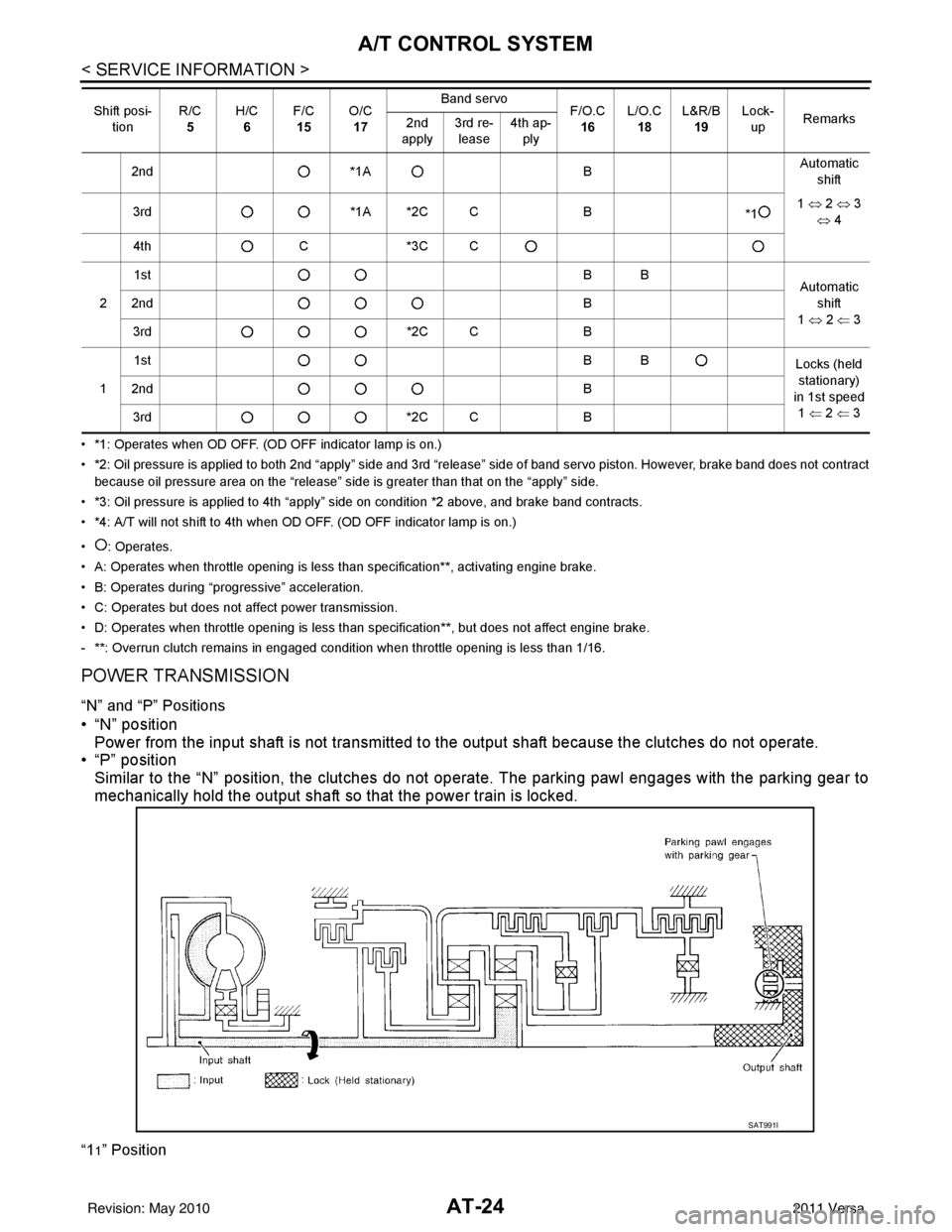
• *1: Operates when OD OFF. (OD OFF indicator lamp is on.)
• *2: Oil pressure is applied to both 2nd “apply” side and 3rd “release” side of band servo piston. However, brake band does not contract
because oil pressure area on the “release” side is greater than that on the “apply” side.
• *3: Oil pressure is applied to 4th “apply” side on condition *2 above, and brake band contracts.
• *4: A/T will not shift to 4th when OD OFF. (OD OFF indicator lamp is on.)
• : Operates.
• A: Operates when throttle opening is less than specification**, activating engine brake.
• B: Operates during “pro gressive” acceleration.
• C: Operates but does not affect power transmission.
• D: Operates when throttle opening is less than specification**, but does not affect engine brake.
- **: Overrun clutch remains in engaged condition when throttle opening is less than 1/16.
POWER TRANSMISSION
“N” and “P” Positions
• “N” position Power from the input shaft is not transmitted to the output shaft because the clutches do not operate.
• “P” position
Similar to the “N” position, the clutches do not operate. The parking pawl engages with the parking gear to
mechanically hold the output shaft so that the power train is locked.
“11” Position
2nd *1A BAutomatic
shift
3rd *1A *2C C B
*11
⇔ 2 ⇔ 3
⇔ 4
4th C*3C C
2 1st
BB
Automatic
shift
1 ⇔ 2 ⇐ 3
2nd
B
3rd *2C CB
1 1st
BB
Locks (held
stationary)
in 1st speed 1 ⇐ 2 ⇐ 3
2nd
B
3rd *2C CB
Shift posi-
tion R/C
5 H/C
6 F/C
15 O/C
17 Band servo
F/O.C
16 L/O.C
18 L&R/B
19 Lock-
up Remarks
2nd
apply 3rd re-
lease 4th ap-
ply
SAT991I
Revision: May 2010 2011 Versa
Page 68 of 3787
TROUBLE DIAGNOSISAT-51
< SERVICE INFORMATION >
DE
F
G H
I
J
K L
M A
B
AT
N
O P
Inspections Before Trouble DiagnosisINFOID:0000000005928094
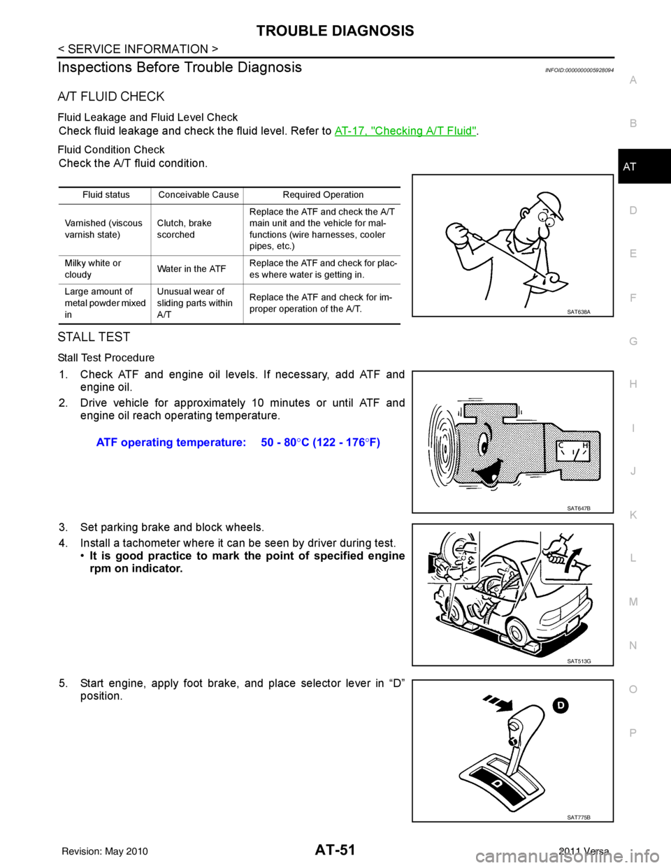
A/T FLUID CHECK
Fluid Leakage and Fluid Level Check
Check fluid leakage and check the fluid level. Refer to AT-17, "Checking A/T Fluid".
Fluid Condition Check
Check the A/T fluid condition.
STALL TEST
Stall Test Procedure
1. Check ATF and engine oil levels. If necessary, add ATF and engine oil.
2. Drive vehicle for approximately 10 minutes or until ATF and engine oil reach operating temperature.
3. Set parking brake and block wheels.
4. Install a tachometer where it can be seen by driver during test. •It is good practice to mark the point of specified engine
rpm on indicator.
5. Start engine, apply foot brake, and place selector lever in “D” position.
Fluid status Conceivable Cause Required Operation
Varnished (viscous
varnish state) Clutch, brake
scorchedReplace the ATF and check the A/T
main unit and the vehicle for mal-
functions (wire harnesses, cooler
pipes, etc.)
Milky white or
cloudy Water in the ATFReplace the ATF and check for plac-
es where water is getting in.
Large amount of
metal powder mixed
in Unusual wear of
sliding parts within
A/T
Replace the ATF and check for im-
proper operation of the A/T.
SAT638A
ATF operating temperature: 50 - 80
°C (122 - 176 °F)
SAT647B
SAT513G
SAT775B
Revision: May 2010 2011 Versa
Page 71 of 3787
AT-54
< SERVICE INFORMATION >
TROUBLE DIAGNOSIS
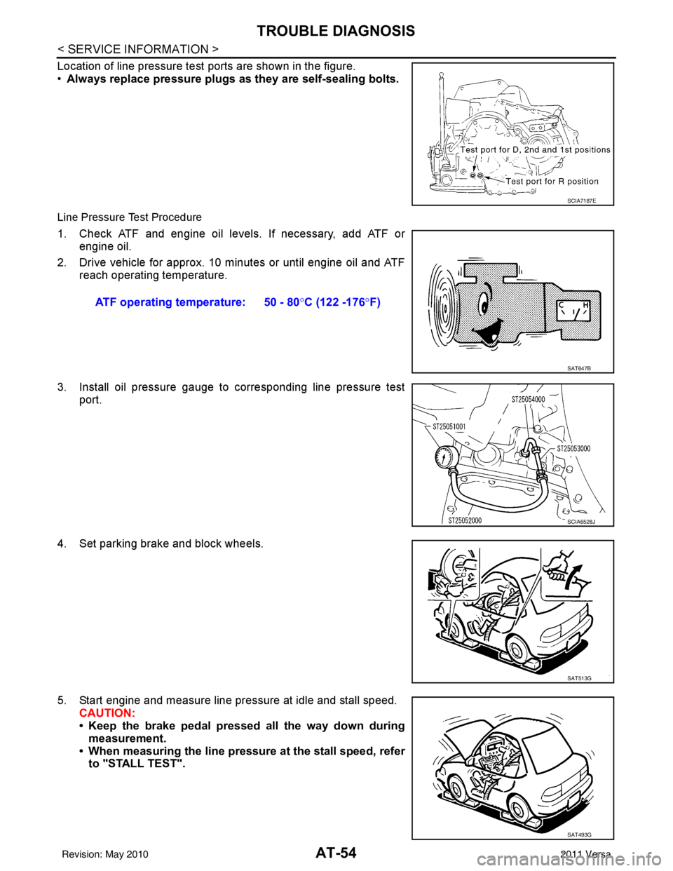
Location of line pressure test ports are shown in the figure.
•Always replace pressure plugs as they are self-sealing bolts.
Line Pressure Test Procedure
1. Check ATF and engine oil levels. If necessary, add ATF or
engine oil.
2. Drive vehicle for approx. 10 minutes or until engine oil and ATF reach operating temperature.
3. Install oil pressure gauge to corresponding line pressure test port.
4. Set parking brake and block wheels.
5. Start engine and measure line pressure at idle and stall speed. CAUTION:
• Keep the brake pedal pressed all the way down duringmeasurement.
• When measuring the line pressure at the stall speed, refer to "STALL TEST".
SCIA7187E
ATF operating temperature: 50 - 80° C (122 -176°F)
SAT647B
SCIA6528J
SAT513G
SAT493G
Revision: May 2010 2011 Versa
Page 74 of 3787
TROUBLE DIAGNOSISAT-57
< SERVICE INFORMATION >
DE
F
G H
I
J
K L
M A
B
AT
N
O P
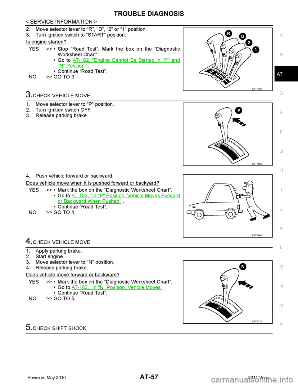
2. Move selector lever to “R”, “D”, “2” or “1” position.
3. Turn ignition switch to “START” position.
Is engine started?
YES >> • Stop “Road Test”. Mark the box on the “Diagnostic Worksheet Chart”.
•Go to AT-182, "
Engine Cannot Be Started in "P" and
"N" Position" .
• Continue “Road Test”.
NO >> GO TO 3.
3.CHECK VEHICLE MOVE
1. Move selector lever to “P” position.
2. Turn ignition switch OFF.
3. Release parking brake.
4. Push vehicle forward or backward.
Does vehicle move when it is pushed forward or backyard?
YES >> • Mark the box on the “D iagnostic Worksheet Chart”.
•Go to AT-183, "
In "P" Position, Vehicle Moves Forward
or Backward When Pushed" .
• Continue “Road Test”.
NO >> GO TO 4.
4.CHECK VEHICLE MOVE
1. Apply parking brake.
2. Start engine.
3. Move selector lever to “N” position.
4. Release parking brake.
Does vehicle move forward or backward?
YES >> • Mark the box on the “D iagnostic Worksheet Chart”.
•Go to AT-183, "
In "N" Position, Vehicle Moves" .
• Continue “Road Test”.
NO >> GO TO 5.
5.CHECK SHIFT SHOCK
SAT770B
SAT768B
SAT796A
SAT771B
Revision: May 2010 2011 Versa
Page 89 of 3787

AT-72
< SERVICE INFORMATION >
TROUBLE DIAGNOSIS
Slips/Will Not EngageRaces extremely fast
or slips in changing
from D
4 to D2 when
depressing accelera-
tor pedal. ON vehicle1. A/T fluid level
AT- 1 7
2. Accelerator pedal position sensorEC-415
(HR16DE), EC-
982 (MR18DE)
3. Line pressure test AT- 5 1
4. Line pressure solenoid valveAT- 1 3 3
5. Shift solenoid valve AAT- 1 3 8
6. Shift solenoid valve BAT- 1 4 3
7. Control valve assemblyAT- 2 2 2
OFF vehicle8. Brake band
AT- 3 3 19. Forward clutchAT- 3 0 7
Races extremely fast
or slips in changing
from D
3 to D2 when
depressing accelera-
tor pedal. ON vehicle1. A/T fluid level
AT- 1 7
2. Accelerator pedal position sensor EC-415
(HR16DE), EC-
982 (MR18DE)
3. Line pressure test AT- 5 1
4. Line pressure solenoid valveAT- 1 3 3
5. Shift solenoid valve BAT- 1 4 3
6. Control valve assemblyAT- 2 2 2
OFF vehicle7. Brake band
AT- 3 3 18. High clutchAT- 3 0 2
Races extremely fast
or slips in changing
from D
4 or D3 to D 1
when depressing ac-
celerator pedal. ON vehicle1. A/T fluid level
AT- 1 7
2. Accelerator pedal position sensorEC-415
(HR16DE), EC-
982 (MR18DE)
3. Line pressure test AT- 5 1
4. Line pressure solenoid valveAT- 1 3 3
5. Shift solenoid valve AAT- 1 3 8
6. Shift solenoid valve BAT- 1 4 3
7. Control valve assemblyAT- 2 2 2
OFF vehicle8. Forward clutch
AT- 3 0 79. Forward one-way clutchAT- 3 1 8
10. Low one-way clutchAT- 2 5 7
Vehicle will not run in
any position.ON vehicle
1. A/T fluid level
AT- 1 7
2. Control cable adjustmentAT- 2 1 7
3. Line pressure testAT- 5 1
4. Line pressure solenoid valveAT- 1 3 3
OFF vehicle5. Oil pump
AT- 2 7 8
6. High clutchAT- 3 0 2
7. Brake bandAT- 3 3 1
8. Low & reverse brakeAT- 3 1 4
9. Torque converterAT- 2 5 7
10. Parking componentsAT- 2 3 7
ItemsSymptom Condition Diagnostic itemReference page
Revision: May 2010 2011 Versa
Page 90 of 3787
TROUBLE DIAGNOSISAT-73
< SERVICE INFORMATION >
DE
F
G H
I
J
K L
M A
B
AT
N
O P
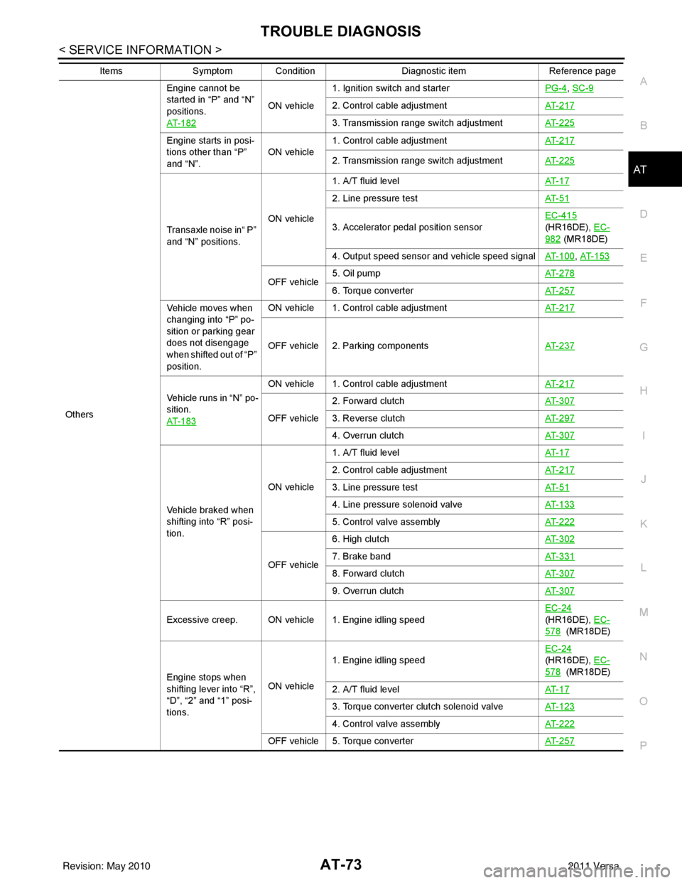
Others Engine cannot be
started in “P” and “N”
positions.
AT- 1 8 2
ON vehicle
1. Ignition switch and starter
PG-4
, SC-9
2. Control cable adjustmentAT- 2 1 7
3. Transmission range switch adjustmentAT- 2 2 5
Engine starts in posi-
tions other than “P”
and “N”.ON vehicle
1. Control cable adjustment
AT- 2 1 7
2. Transmission range switch adjustmentAT- 2 2 5
Transaxle noise in“ P”
and “N” positions.ON vehicle1. A/T fluid level
AT- 1 7
2. Line pressure testAT- 5 1
3. Accelerator pedal position sensorEC-415
(HR16DE), EC-
982 (MR18DE)
4. Output speed sensor and vehicle speed signal AT- 1 0 0
, AT- 1 5 3
OFF vehicle5. Oil pump
AT- 2 7 86. Torque converterAT- 2 5 7
Vehicle moves when
changing into “P” po-
sition or parking gear
does not disengage
when shifted out of “P”
position.ON vehicle 1. Control cable adjustment
AT- 2 1 7
OFF vehicle 2. Parking componentsAT- 2 3 7
Vehicle runs in “N” po-
sition.
AT- 1 8 3
ON vehicle 1. Control cable adjustmentAT- 2 1 7
OFF vehicle2. Forward clutch
AT- 3 0 73. Reverse clutchAT- 2 9 7
4. Overrun clutchAT- 3 0 7
Vehicle braked when
shifting into “R” posi-
tion.ON vehicle
1. A/T fluid level
AT- 1 7
2. Control cable adjustmentAT- 2 1 7
3. Line pressure testAT- 5 1
4. Line pressure solenoid valveAT- 1 3 3
5. Control valve assemblyAT- 2 2 2
OFF vehicle6. High clutch
AT- 3 0 27. Brake band AT- 3 3 1
8. Forward clutchAT- 3 0 7
9. Overrun clutchAT- 3 0 7
Excessive creep. ON vehicle 1. Engine idling speed EC-24
(HR16DE), EC-
578 (MR18DE)
Engine stops when
shifting lever into “R”,
“D”, “2” and “1” posi-
tions. ON vehicle
1. Engine idling speed
EC-24
(HR16DE), EC-
578 (MR18DE)
2. A/T fluid level AT- 1 7
3. Torque converter clutch solenoid valveAT- 1 2 3
4. Control valve assemblyAT- 2 2 2
OFF vehicle 5. Torque converter AT- 2 5 7
ItemsSymptom Condition Diagnostic itemReference page
Revision: May 2010 2011 Versa
Page 231 of 3787
AT-214
< SERVICE INFORMATION >
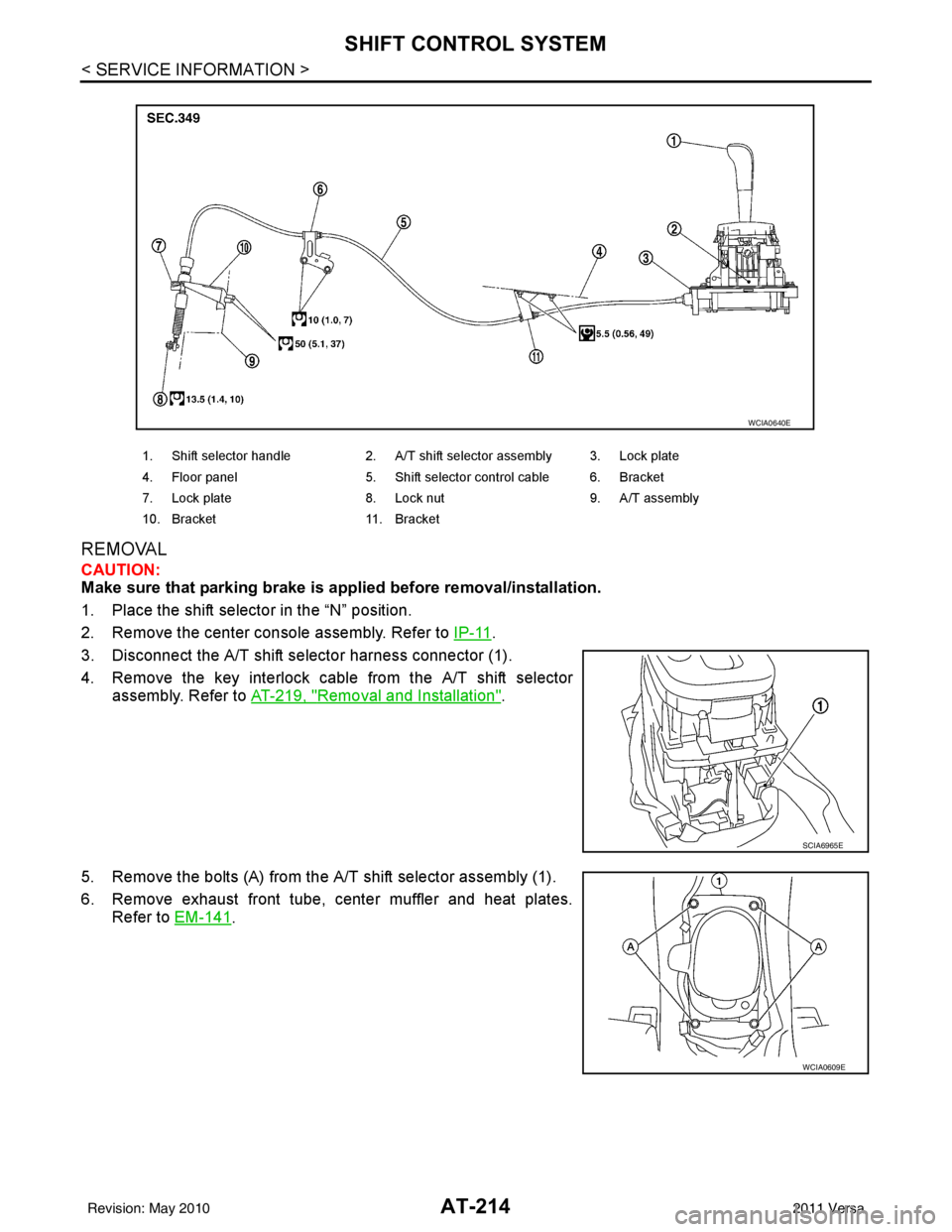
SHIFT CONTROL SYSTEM
REMOVAL
CAUTION:
Make sure that parking brake is applied before removal/installation.
1. Place the shift selector in the “N” position.
2. Remove the center console assembly. Refer to IP-11
.
3. Disconnect the A/T shift selector harness connector (1).
4. Remove the key interlock cable from the A/T shift selector assembly. Refer to AT-219, "
Removal and Installation".
5. Remove the bolts (A) from the A/T shift selector assembly (1).
6. Remove exhaust front tube, center muffler and heat plates. Refer to EM-141
.
1. Shift selector handle 2. A/T shift selector assembly 3. Lock plate
4. Floor panel 5. Shift selector control cable 6. Bracket
7. Lock plate 8. Lock nut 9. A/T assembly
10. Bracket 11. Bracket
WCIA0640E
SCIA6965E
WCIA0609E
Revision: May 2010 2011 Versa