steering wheel NISSAN TITAN 2017 2.G User Guide
[x] Cancel search | Manufacturer: NISSAN, Model Year: 2017, Model line: TITAN, Model: NISSAN TITAN 2017 2.GPages: 671, PDF Size: 7.96 MB
Page 96 of 671
box. The supplemental front air bags are de-
signed to inflate in higher severity frontal colli-
sions, although they may inflate if the forces in
another type of collision are similar to those of a
higher severity frontal impact. They may not in-
flate in certain frontal collisions. Vehicle damage
(or lack of it) is not always an indication of proper
front air bag system operation.
The supplemental air bag system monitors infor-
mation from the crash zone sensor, the Air bag
Control Unit (ACU) and seat belt buckle sensors
that detect if the seat belts are fastened. Inflator
operation is based on the severity of a collision
and whether the seat belts are being used. Only
one front air bag may inflate in a crash, depending
on the crash severity and whether the front occu-
pants are belted or unbelted. This does not indi-
cate improper performance of the system. If you
have any questions about the performance of
your air bag system, it is recommended that you
visit a NISSAN dealer to obtain information about
the system.
If you have any questions about your air bag
system, it is recommended that you visit a
NISSAN dealer to obtain information about the
system. If you are considering modification of
your vehicle due to a disability, you may also
contact NISSAN. Contact information is con-
tained in the beginning of this Owner’s Manual.When a front air bag inflates, a fairly loud noise
may be heard, followed by the release of smoke.
This smoke is not harmful and does not indicate a
fire. Care should be taken to not inhale it, as it may
cause irritation and choking. Those with a history
of a breathing condition should get fresh air
promptly.
Front air bags, along with the use of seat belts,
help to cushion the impact force on the face and
chest of the driver and right front passenger. They
can help save lives and reduce serious injuries.
However, an inflating front air bag may cause
facial abrasions or other injuries. Front air bags
do not provide restraint to the lower body.
Seat belts should be correctly worn and the
driver and passenger seated upright as far as
practical away from the steering wheel or instru-
ment panel. The front air bags inflate quickly in
order to help protect the front occupants. Be-
cause of this, the force of the front air bag inflating
can increase the risk of injury if the occupant is
too close to, or is against, the front air bag module
during inflation.
The front air bags deflate quickly after a collision.
The front air bags operate only when the
ignition switch is in the ON or START posi-
tion.
After turning the ignition key to the ON
position, the supplemental air bag warning
light illuminates. The supplemental air bag
warning light will turn off after about 7 sec-
onds if the system is operational.
WARNING
●
Do not place any objects on the steering
wheel pad or on the instrument panel.
Also, do not place any objects between
any occupant and the steering wheel or
instrument panel. Such objects may be-
come dangerous projectiles and cause
injury if the front air bag inflates.
● Immediately after inflation, several
front air bag system components will be
hot. Do not touch them; you may se-
verely burn yourself.
● No unauthorized changes should be
made to any components or wiring of
the supplemental air bag system. This is
to prevent accidental inflation of the
supplemental air bag or damage to the
supplemental air bag system.
● Do not make unauthorized changes to
your vehicle’s electrical system, sus-
pension system or front end structure.
This could affect proper operation of
the front air bag system.
Safety—Seats, seat belts and supplemental restraint system1-73
Page 97 of 671
●If your vehicle has front recovery hooks
as original factory equipment do not
remove or modify them. If it was not
equipped with front recovery hooks do
not install them. Either action could af-
fect proper operation of the front air
bag system resulting in injury or death.
● Tampering with the front air bag system
may result in serious personal injury.
Tampering includes changes to the
steering wheel and the instrument
panel assembly by placing material
over the steering wheel pad and above
the instrument panel or by installing
additional trim material around the air
bag system.
● No unauthorized changes should be
made to any components or wiring of
the seat belt system. This may affect the
front air bag system. Tampering with
the seat belt system may result in seri-
ous personal injury. ●
It is recommended that you visit a
NISSAN dealer for work on and around
the front air bag. It is also recom-
mended that you visit a NISSAN dealer
for installation of electrical equipment.
The Supplemental Restraint System
(SRS) wiring* should not be modified or
disconnected. Unauthorized electrical
test equipment and probing devices
should not be used on the air bag
system.
● A cracked windshield should be re-
placed immediately by a qualified repair
facility. A cracked windshield could af-
fect the function of the supplemental air
bag system.
*The SRS wiring harness connectors are
yellow and orange for easy identification.
When selling your vehicle, we request that you
inform the buyer about the front air bag system
and guide the buyer to the appropriate sections
in this Owner’s Manual.
FRONT SEAT-MOUNTED SIDE-
IMPACT SUPPLEMENTAL AIR BAG
AND ROOF-MOUNTED CURTAIN
SIDE-IMPACT AND ROLLOVER
SUPPLEMENTAL AIR BAG SYSTEMS
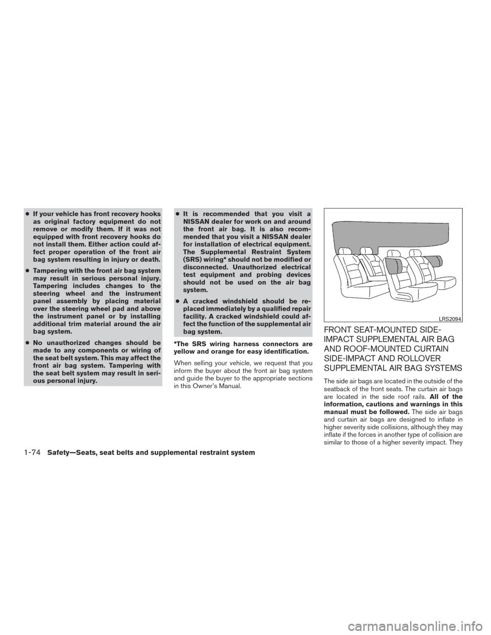
The side air bags are located in the outside of the
seatback of the front seats. The curtain air bags
are located in the side roof rails. All of the
information, cautions and warnings in this
manual must be followed. The side air bags
and curtain air bags are designed to inflate in
higher severity side collisions, although they may
inflate if the forces in another type of collision are
similar to those of a higher severity impact. They
LRS2094
1-74Safety—Seats, seat belts and supplemental restraint system
Page 105 of 671
Heated rear seat switches (if so equipped)..........2-61
Heated steering wheel switch (if so equipped) .......2-62
Warning systems switch (if so equipped) ............2-63
Vehicle Dynamic Control (VDC) off switch . . .........2-63
Hill descent control switch (if so equipped) ..........2-64
Electronic locking rear differential (E-Lock) system
switch (if so equipped) ............................ 2-65
Power inverter switch (if so equipped) ..............2-67
Parking Sensor (sonar) System OFF Switch
(if so equipped) .................................. 2-67
Tow mode switch (if so equipped) . . ................2-68
E-call (SOS) switch (if so equipped) ................2-69
Trailer Brake Controller Unit (TBCU)
(if so equipped) .................................. 2-69
Power outlets .................................... 2-69
12v Outlets . . ................................. 2-69
120v outlets (if so equipped) ...................2-72
Extended storage switch .......................... 2-73
Storage ......................................... 2-74
Front-door pockets ............................ 2-74
Console side pockets .......................... 2-75
Seatback pockets (if so equipped) ..............2-75
Under-seat storage (if so equipped) .............2-76
Console box storage trays (if so equipped) .......2-77 Glove box
.................................... 2-77
Console box (if so equipped) ...................2-77
Center armrest storage (if so equipped) ..........2-78
Under front seat storage bin (if so equipped) .....2-79
Sunglasses holder (if so equipped) ..............2-79
Cup holders .................................. 2-80
Grocery hooks (if so equipped) .................2-82
Bed liner storage bins (if so equipped) ...........2-82
Windows ........................................ 2-83
Power windows ............................... 2-83
Rear power window switch (if so equipped) ......2-85
Rear sliding window (if so equipped) ............2-86
Interior
lights ..................................... 2-87
Console light (if so equipped) ...................2-88
Map lights (if so equipped) .....................2-88
Personal Lights (if so equipped) .................2-89
Homelink® Universal Transceiver (if so equipped) ....2-89
Programming HomeLink® ......................2-90
Programming HomeLink® for Canadian
customers and gate openers ....................2-91
Operating the HomeLink® Universal
Transceiver ................................... 2-92
Programming trouble-diagnosis .................2-92
Page 107 of 671
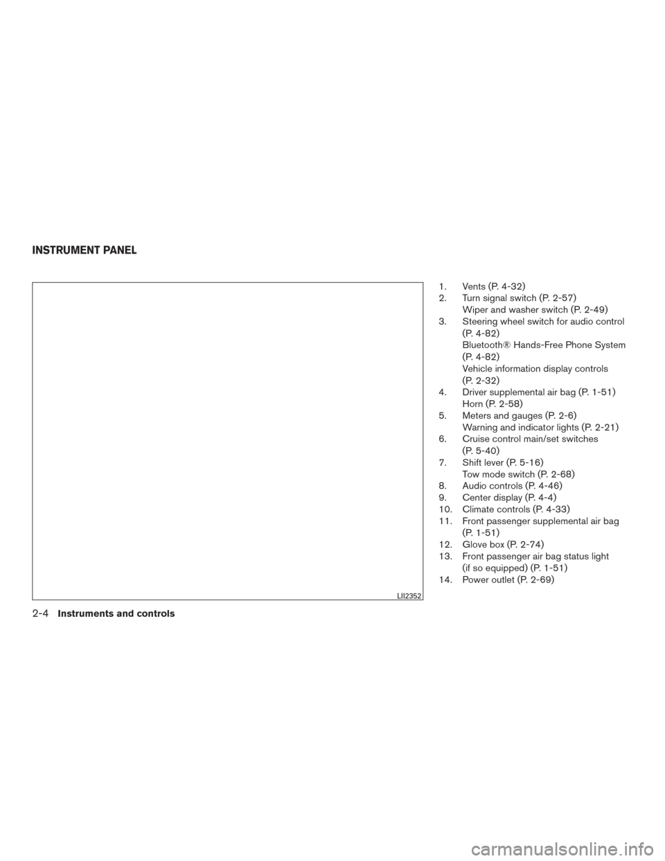
1. Vents (P. 4-32)
2. Turn signal switch (P. 2-57)Wiper and washer switch (P. 2-49)
3. Steering wheel switch for audio control
(P. 4-82)
Bluetooth® Hands-Free Phone System
(P. 4-82)
Vehicle information display controls
(P. 2-32)
4. Driver supplemental air bag (P. 1-51) Horn (P. 2-58)
5. Meters and gauges (P. 2-6) Warning and indicator lights (P. 2-21)
6. Cruise control main/set switches
(P. 5-40)
7. Shift lever (P. 5-16) Tow mode switch (P. 2-68)
8. Audio controls (P. 4-46)
9. Center display (P. 4-4)
10. Climate controls (P. 4-33)
11. Front passenger supplemental air bag
(P. 1-51)
12. Glove box (P. 2-74)
13. Front passenger air bag status light
(if so equipped) (P. 1-51)
14. Power outlet (P. 2-69)
LII2352
INSTRUMENT PANEL
2-4Instruments and controls
Page 108 of 671
15. Heated steering wheel switch(if so equipped) (P. 2-62)
Warning Systems switch
(if so equipped) (P. 2-63)
16. Power outlet (P. 2-69)
17. Auxiliary jack (P. 4-46) USB port (P. 4-46)
18. Hazard warning flasher switch (P. 6-2)
19. Trailer Brake Controller Unit
(if so equipped) (P. 2-69)
20. Climate control seat switch
(if so equipped) (P. 2-58)
Heated front seat switches
(if so equipped) (P. 2-60)
21. Vehicle Dynamic Control (VDC) OFF
switch (P. 2-63)
Parking sensor (sonar) system OFF
switch (if so equipped) (P. 2-67)
22. 4WD shift switch (if so equipped)
(P. 5-44)
23. Push-button ignition switch (P. 5-10)
24. Tilt and telescopic steering wheel
control (P. 3-25)
25. Headlight aiming control
(if so equipped) (P. 2-53)
Power inverter switch (if so equipped)
(P. 2-67) Cargo lamp switch (P. 2-58)
Electronic locking rear differential
(E-Lock) system switch (if so
equipped) (P. 2-65)
Hill descent control system switch
(if so equipped) (P. 2-64)
26. Headlight switch (P. 2-53) Fog light switch (if so equipped)
(P. 2-57)
Instrument brightness control switches
(P. 2-53)
Trip reset switch (P. 2-6)
Refer to the page number indicated in pa-
renthesis for operating details.
Instruments and controls2-5
Page 116 of 671
OFF-ROAD MONITOR (if so
equipped)
The off-road monitor displays the various slopes
of the vehicle.
The Pitch Gauge (left) indicates the angle of the
vehicle position up or down. The value will be
displayed below the gauge while the vehicle
graphic will rotate to indicate condition pointed
up or down.
The Tire Angle (center) indicates the angle of the
tires based on turning of the steering wheel. The
graphic image will show the actual vehicle tire
position while the angle is to be displayed below
as reference.The Roll Gauge (right) indicates the angle of the
vehicle position left and right. The value will be
displayed below the gauge while the vehicle
graphic will rotate to indicate condition of the
vehicle leaning to the left or right.
TRIP COMPUTER (if so equipped)
When the ignition switch is placed in the ON
position, the modes of the trip computer can be
selected by pressing the
buttons on the
steering wheel. The following modes can be se-
lected:
● Range
● Average fuel economy
● Average speed
● Time
● Tire info
● Settings
Range
The range mode provides you with an estimation
of the distance that can be driven before refuel-
ing. The range is constantly being calculated,
based on the amount of fuel in the fuel tank and
the actual fuel economy which will depend on
driving conditions. Dashes (—) indicate that fuel
remaining volume cannot be read by the fuel
pump and should be refilled as soon as possible.
The display is updated every 30 seconds.
LIC3417LIC3504
Instruments and controls2-13
Page 117 of 671
NOTE:
When driving uphill or rounding curves, the
fuel in the tank shifts, which may momen-
tarily change the display.
Average fuel economy
The average fuel economy mode shows the av-
erage fuel economy since the last reset. Reset-
ting is done by pressing the ENTER button on the
steering wheel for more than approximately
1 second. The display is updated every 30 sec-
onds. At about the first 1/3 mile (500 m) after a
reset, the display shows (----) .
Average speed
The average speed mode shows the average
vehicle speed since last reset. Resetting is done
by pressing the ENTER button on the steering
wheel for more than approximately 1 second. The
display is updated every 30 seconds. The first
30 seconds after a reset, the display shows
(----) .
LIC3505LIC3506
2-14Instruments and controls
Page 118 of 671
Time
The time mode shows the time the vehicle has
been on since the last reset. The displayed time
can be reset by pressing the ENTER button on
the steering wheel for more than approximately
1 second.
Tire info
The tire info mode shows the pressure of each
tire. To see the individual tire pressures, press the
ENTER button when the desired tire is shown.
The tire pressures are displayed as follows:● FL (Front Left)
● FR (Front Right)
● RL (Rear Left)
● RR (Rear Right)
To return to the main menu selections, scroll to
“EXIT” and press ENTER.
Settings
The settings mode allows the user to change the
trip computer display units and set maintenance
reminders. To select the desired menu item,
press the ENTER button when it is shown. The
menu items are displayed as follows:
● Engine Oil
● Oil Filter
● Rotation
● Other
● Units
LIC3507LIC3508LIC3509
Instruments and controls2-15
Page 135 of 671
The vehicle information display is located to the
left of the speedometer. It displays such items as:● Vehicle settings
● Trip computer information
● Drive system warnings and settings (if so
equipped)
● Cruise control system information
● Blind Spot Warning (BSW) system (if so
equipped)
● Rear Cross Traffic Alert (RCTA) system (if so
equipped) ●
NISSAN Intelligent Key® operation informa-
tion
● Indicators and warnings
● Tire Pressure informationHOW TO USE THE VEHICLE
INFORMATION DISPLAY
The vehicle information display can be navigated
using the ENTER and
buttons located on
the steering wheel.
1. ENTER — press to select the vehicle infor- mation menu items. Additionally, use the
UP/DOWN
function to navigate the
menu items
2.
— move LEFT/RIGHT to navigate
through the items in the vehicle information
display
LIC2630LIC3391
VEHICLE INFORMATION DISPLAY (if
so equipped)
2-32Instruments and controls
Page 136 of 671
The ENTER button also controls audio functions.
For additional information, refer to “Steering
wheel switch for audio control” in the “Monitor,
climate, audio, phone and voice recognition sys-
tems” section of this manual.
STARTUP DISPLAY
When the vehicle is placed in the ON or ACC (if
so equipped) position, the vehicle information
display may display the following screens:● Home
● Off Road
● Auxiliary Gauges (if so equipped)
● DEF Level (if so equipped)
● Trip
● Fuel Economy
● Navigation (if so equipped)
● Audio
● Driving Aids (if so equipped)
● Tire Pressures
● Warning Confirmation
● Settings Warning Confirmation will only display if there are
any warnings present. For additional information,
refer to “Vehicle information display warnings and
indicators” in this section.
To control which items display in the vehicle
information display, refer to “Settings” in this sec-
tion.
SETTINGS
The setting mode allows you to change the infor-
mation displayed in the vehicle information dis-
play:
● Driver Assistance (if so equipped)
● Meter Settings
● Vehicle Settings
● Towing Settings (if so equipped)
● Alarm (if so equipped)
● Maintenance
● Unit
● Language
● Factory Reset
Instruments and controls2-33