brake fluid NISSAN TITAN 2017 2.G Owners Manual
[x] Cancel search | Manufacturer: NISSAN, Model Year: 2017, Model line: TITAN, Model: NISSAN TITAN 2017 2.GPages: 671, PDF Size: 7.96 MB
Page 17 of 671
Cummins 5.0 L engine
1. Windshield-washer fluid reservoir(P. 8-13)
2. Fuse box (P. 8-21)
3. Fuse/Fusible link box (P. 8-21)
4. Engine coolant reservoir*
5. Fuel filter (Stage 2)*
6. Engine oil filler cap*
7. Brake fluid reservoir (P. 8-13)
8. Air cleaner*
9. Battery (P. 8-14)
10. Power steering fluid reservoir (P. 8-12)
11. Radiator cap*
12. Engine oil dipstick*
13. Drive belt location*
14. Fuse/Fusible link box (P. 8-21)
15. Battery (P. 8-14)
*: Refer to the separate Titan Diesel Owner’s
Manual.
Refer to the page number indicated in pa-
rentheses for operating details.
LDI2870
ENGINE COMPARTMENT CHECK
LOCATIONS
0-8Illustrated table of contents
Page 18 of 671
VK56VD engine (non-XD model)
1. Windshield-washer fluid reservoir(P. 8-13)
2. Fuse box (P. 8-21)
3. Engine oil dipstick (P. 8-7)
4. Power steering fluid reservoir (P. 8-12)
5. Engine oil filler cap (P. 8-7)
6. Brake fluid reservoir (P. 8-13)
7. Air cleaner (P. 8-18)
8. Fuse/Fusible link box (P. 8-21)
9. Drive belt location (P. 8-17)
10. Radiator cap (P. 8-5)
11. Battery (P. 8-14)
12. Engine coolant reservoir (P. 8-5)
Refer to the page number indicated in pa-
rentheses for operating details.
LDI3056
Illustrated table of contents0-9
Page 19 of 671
VK56VD engine (XD model)
1. Windshield-washer fluid reservoir(P. 8-13)
2. Fuse box (P. 8-21)
3. Engine oil dipstick (P. 8-7)
4. Power steering fluid reservoir (P. 8-12)
5. Engine oil filler cap (P. 8-7)
6. Brake fluid reservoir (P. 8-13)
7. Air cleaner (P. 8-18)
8. Fuse/Fusible link box (P. 8-21)
9. Engine coolant reservoir (P. 8-5)
10. Drive belt location (P. 8-17)
11. Battery (P. 8-14)
12. Radiator cap (P. 8-5)
Refer to the page number indicated in pa-
rentheses for operating details.
LDI2973
0-10Illustrated table of contents
Page 127 of 671
●Shift the 4WD switch into the 2WD, 4H
or 4LO position again to turn off the ATP
warning light when the shift lever to the
P position and the ATP warning light is
ON. (Before shifting the 4WD switch
into the 4LO position, move the shift
lever to the N position once, shift the
shift lever into P again and make sure
the ATP warning light is OFF.)
This light indicates that the automatic transmis-
sion parking function is not engaged. If the trans-
fer control is not secured in any drive position
while the shift lever is in the P (Park) position, the
transmission will disengage and the drive wheels
will not lock.
orBrake warning light
This light functions for both the parking brake and
the foot brake systems.
Parking brake indicator
When the ignition switch is placed in the ON
position, the light comes on when the parking
brake is applied.
Low brake fluid warning light
When the ignition switch is placed in the ON
position, the light warns of a low brake fluid level.
If the light comes on while the engine is running, with the parking brake not applied, stop the ve-
hicle and perform the following:
1. Check the brake fluid level. Add brake fluid as necessary. For additional information, re-
fer to “Brake fluid” in the “Do-it-yourself”
section of this manual.
2. If the brake fluid level is correct, have the warning system checked. It is recommended
that you visit a NISSAN dealer for this ser-
vice.
WARNING
●Your brake system may not be working
properly if the warning light is on. Driv-
ing could be dangerous. If you judge it
to be safe, drive carefully to the nearest
service station for repairs. Otherwise,
have your vehicle towed because driv-
ing it could be dangerous.
● Pressing the brake pedal with the en-
gine stopped and/or a low brake fluid
level may increase your stopping dis-
tance and braking will require greater
pedal effort and pedal travel. ●
If the brake fluid level is below the
MINIMUM or MIN mark on the brake
fluid reservoir, do not drive until the
brake system has been checked. It is
recommended that you visit a NISSAN
dealer for this service.
Anti-lock Braking System (ABS) warning
indicator
When the parking brake is released and the
brake fluid level is sufficient, if both the brake
warning light and the ABS warning light illumi-
nate, it may indicate the ABS is not functioning
properly. Have the brake system checked and, if
necessary, repaired. It is recommended that you
visit a NISSAN dealer for this service. Avoid
high-speed driving and abrupt braking. For addi-
tional information, refer to “Anti-lock Braking Sys-
tem (ABS) warning light” in this section.
Charge warning light
If this light comes on while the engine is running,
it may indicate the charging system is not func-
tioning properly. Turn the engine off and check
the generator belt. If the belt is loose, broken,
missing, or if the light remains on, have the sys-
tem checked. It is recommended that you visit a
NISSAN dealer for this service.
2-24Instruments and controls
Page 130 of 671
●Since the spare tire is not equipped with
TPMS, when a spare tire is mounted or a
wheel is replaced the TPMS will not
function and the low tire pressure warn-
ing light will flash for approximately
1 minute. The light will remain on after
1 minute. Have your tires replaced
and/or TPMS system reset as soon as
possible. It is recommended that you
visit a NISSAN dealer for these services.
● Replacing tires with those not originally
specified by NISSAN could affect the
proper operation of the TPMS.
CAUTION
● The TPMS is not a substitute for the
regular tire pressure check. Be sure to
check the tire pressure regularly.
● If the vehicle is being driven at speeds
of less than 16 mph (25 km/h), the
TPMS may not operate correctly.
● Be sure to install the specified size of
tires to the four wheels correctly.
Malfunction Warning Light
(red) (if so equipped)
If this warning light illuminates this indicates ei-
ther the coolant temperature is above a critical threshold or the exhaust temperatures are above
a critical threshold. When illuminated this lamp
indicates the need to stop the engine as soon as
it can be safely done. The engine must remain
shut down until the engine can be repaired. For
additional information, refer to the “Titan Diesel
Owner’s Manual”.
CAUTION
●
Continuing vehicle operation without
proper servicing of the engine control
system could lead to poor driveability,
reduced fuel economy, and damage to
the engine control system, which may
affect the vehicle’s warranty coverage.
● Failure to drain the water from the fuel
filter can cause serious damage to the
engine. It is recommended that you con-
tact a NISSAN dealer as soon as
possible.
Master warning light (if so
equipped)
This light comes on when various vehicle infor-
mation display warnings appear.
● No key warning
● Low fuel warning
● Low windshield-washer fluid warning ●
Parking brake release warning
● Door open warning
● Loose fuel cap warning
● Check tire pressure warning
● 4WD error (if so equipped)
● Front & rear tire size differences (if so
equipped)
NISSAN Intelligent Key®
warning light (if so equipped)
After the ignition switch is placed in the ON
position, this light comes on for about 2 seconds
and then turns off. This light illuminates or blinks
as follows:
● The light blinks in yellow when the door is
closed with the Intelligent Key left outside
the vehicle and the ignition switch in the
ACC or ON position. Make sure that the
Intelligent Key is inside the vehicle.
● The light blinks in green when the Intelligent
Key battery is running out of power. Replace
the battery with a new one. For additional
information, refer to “Battery” in the “Do-it-
yourself” section of this manual.
Instruments and controls2-27
Page 141 of 671
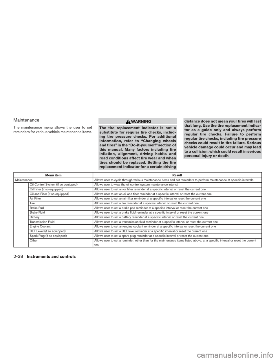
Maintenance
The maintenance menu allows the user to set
reminders for various vehicle maintenance items.
WARNING
The tire replacement indicator is not a
substitute for regular tire checks, includ-
ing tire pressure checks. For additional
information, refer to “Changing wheels
and tires” in the “Do-it-yourself” section of
this manual. Many factors including tire
inflation, alignment, driving habits and
road conditions affect tire wear and when
tires should be replaced. Setting the tire
replacement indicator for a certain drivingdistance does not mean your tires will last
that long. Use the tire replacement indica-
tor as a guide only and always perform
regular tire checks. Failure to perform
regular tire checks, including tire pressure
checks could result in tire failure. Serious
vehicle damage could occur and may lead
to a collision, which could result in serious
personal injury or death.
Menu item
Result
Maintenance Allows user to cycle through various maintenance items and set reminders to perform maintenance at specific intervals
Oil Control System (if so equipped) Allows user to view the oil control system maintenance interval
Oil Filter (if so equipped) Allows user to set an oil filter reminder at a specific interval or reset the current one
Oil and Filter (if so equipped) Allows user to set an oil and filter reminder at a specific interval or reset the current one
Air Filter Allows user to set an air filter reminder at a specific interval or reset the current one
Tire Allows user to set a tire reminder at a specific interval or reset the current one
Brake Pad Allows user to set a brake pad reminder at a specific interval or reset the current one
Brake Fluid Allows user to set a brake fluid reminder at a specific interval or reset the current one
Battery Allows user to set a battery reminder at a specific interval or reset the current one
Transmission Fluid Allows user to set a transmission fluid reminder at a specific interval or reset the current one
Engine Coolant Allows user to set an engine coolant reminder at a specific interval or reset the current one
DEF Level (if so equipped) Allows user to set a DEF level reminder at a specific interval or reset the current one
Spark Plug (if so equipped) Allows user to set a spark plug reminder at a specific interval or reset the current one
Other Allows user to set a reminder, other than for the maintenance items listed above, at a specific interval or reset the current
one
2-38Instruments and controls
Page 144 of 671
VEHICLE INFORMATION DISPLAY
WARNINGS AND INDICATORS
1. Door Open
2. Release Parking Brake
3. Range XX miles
4. Low Fuel
5. Oil Level Low (For Diesel engines only)
6. Low Oil Pressure Stop Vehicle (For Dieselengines only)
7. Oil Level Sensor Fault (For Diesel engines only)
8. AT (Automatic Transmission) CHECK
9. AT (Automatic Transmission) Error: See Owner’s Manual
10. Tire Pressure Low - Add Air
11. Low Tire Pressure Error — Info
12. Flat Tire
13. Shipping Mode On Push Storage Fuse
14. Push brake and start button to drive
15. Remote Engine Start Mode (if so equipped)
16. Brightness indicator
17. Low Outside Temperature 18. Shift to Park
19. Low Fuel Pressure Service Fuel System
20. Low Washer Fluid
21. Cruise control indicator
22. 4WD shift indicators (if so equipped)
23. FRT & RR tire size difference: See Owner’s
Manual (if so equipped)
24. Push Ignition to OFF
25. Headlight System Error: See Owner’s Manual (if so equipped)
26. Key ID Incorrect
27. No Key Detected
28. Key System Error: See Owner’s Manual
29. Key Battery Low
30. Power will turn off to save the battery
31. Power turned off to save the battery
32. Reminder: Turn OFF Headlights
33. 4WD Error: See Owner’s Manual (if so equipped)
34. Battery Voltage Low Charge Battery
35. Maintenance indicators 36. Parking Sensor Error: See Owner’s Manual
(if so equipped)
37. TPMS Error: See Owner’s Manual
38. 4WD MODE SHIFTING (if so equipped)
39. Loose Fuel Cap (if so equipped)
40. Blind Spot Warning (BSW) and Rear Cross Traffic Alert (RCTA) indicator (if so
equipped)
41. Malfunction: See Owner’s Manual (if so equipped)
Door Open
This warning illuminates when a door has been
opened.
Release Parking Brake
This warning illuminates in the message area of
the vehicle information display when the parking
brake is set and the vehicle is driven. Press the
brake pedal to release the parking brake.
Range XX miles
This warning illuminates to indicate the approxi-
mate distance remaining before the fuel reaches
0 (Empty) .
Instruments and controls2-41
Page 146 of 671
refer to “Extended storage switch” in the “Instru-
ments and controls” section of this manual.
Push brake and start button to drive
This indicator appears when the shift lever is in
the P (Park) position.
This indicator means that the engine will start by
pushing the ignition switch with the brake pedal
depressed. You can start the engine from any
position of the ignition switch.
Remote Engine Start Mode (if so
equipped)
This warning appears in the vehicle information
display when the vehicle has been started using
the remote start function. To start the vehicle,
apply the brake and place the ignition switch in
the ON position.
Brightness indicator
This indicator appears when the vehicle informa-
tion display screen brightness is being adjusted.
Low Outside Temperature
This warning appears if the outside temperature
is below 37°F (3°C) . The temperature can be
changed to display in Celsius or Fahrenheit. For
additional information, refer to “Settings” in this
section.Shift to Park
This warning illuminates when the ignition switch
is in the ACC or OFF position and the shift lever
is not in the P (Park) position. Also, a chime
sounds when the ignition switch is in the ACC or
OFF position.
If this warning illuminates, move the shift lever to
the P (Park) position and start the engine.
Low Fuel Pressure Service Fuel System
This warning appears when the fuel pressure is
low. Check the fuel level and refuel if needed. If
the warning remains illuminated, have the system
checked. It is recommended that you visit a
NISSAN dealer for this service. For additional
information, refer to “Diesel fuel system” in the
“Introduction” of the “Titan Diesel Owner’s
Manual”.
CAUTION
Since the fuel pump is lubricated by the
fuel itself, prolonged driving with low fuel
levels may cause progressive damage to
the fuel pump. This may cause the pump to
fail.
Low Washer Fluid
This warning illuminates when the windshield-
washer fluid is at a low level. Add windshield- washer fluid as necessary. For additional informa-
tion, refer to “Windshield-washer fluid” in the
“Do-it-yourself” section of this manual.
Cruise control indicator
This indicator shows the cruise control system
status.
For additional information, refer to “Cruise con-
trol” in the “Starting and driving” section of this
manual.
4WD shift indicators (if so equipped)
These indicators show which 4WD mode is se-
lected. For additional information, refer to “Using
4–wheel drive (4WD)” in the “Starting and driv-
ing” section of this manual.
FRT & RR tire size difference: See Own-
er’s Manual (if so equipped)
This warning may appear if there is a large differ-
ence between the diameters of the front and rear
wheels. Pull off the road in a safe area, with the
engine idling. Check that all the tire sizes are the
same, that the tire pressure is correct and that the
tires are not excessively worn. For additional in-
formation, refer to “Wheels and tires” in the
“Technical and consumer information” of this
manual.
Instruments and controls2-43
Page 391 of 671
NISSAN VEHICLE IMMOBILIZER
SYSTEM
The NISSAN Vehicle Immobilizer System will not
allow the engine to start without the use of the
registered key.
If the engine fails to start using a registered key
(for example, when interference is caused by
another registered key, an automated toll road
device or automatic payment device on the key
ring) , restart the engine using the following pro-
cedures:1. Leave the ignition switch in the ON position for approximately 5 seconds.
2. Turn the ignition switch to the OFF or LOCK position, and wait approximately 10 sec-
onds.
3. Repeat steps 1 and 2.
4. Restart the engine while holding the device (which may have caused the interference)
separate from the registered key.
If the no start condition re-occurs, NISSAN rec-
ommends placing the registered key on a sepa-
rate key ring to avoid interference from other
devices. ●
Make sure the area around the vehicle is
clear.
● Check fluid levels such as engine oil, cool-
ant, brake fluid, DEF (Diesel only) and
windshield-washer fluid as frequently as
possible, or at least whenever you refuel.
● Check that all windows and lights are clean.
● Visually inspect tires for their appearance
and condition. Also check tires for proper
inflation.
● Check that all doors are closed.
● Position seat and adjust head
restraints/headrests.
● Adjust inside and outside mirrors.
● Fasten seat belts and ask all passengers to
do likewise.
● Check the operation of warning lights when
the ignition switch is placed in the ON posi-
tion. For additional information, refer to
“Warning lights, indicator lights and audible
reminders” in the “Instruments and controls”
section of this manual. 1. Apply the parking brake.
2. Move the shift lever to P (Park) or N (Neu-
tral) . P (Park) is recommended.
The starter is designed not to operate
unless the shift lever is in either P
(Park) or N (Neutral) .
3. Push the ignition switch to the ON position. Depress the brake pedal and push the igni-
tion switch to start the engine.
To start the engine immediately, push and
release the ignition switch while depressing
the brake pedal with the ignition switch in
any position.
● If the engine is very hard to start in ex-
tremely cold weather or when restarting,
depress the accelerator pedal a little (ap-
proximately 1/3 to the floor) and while
holding, crank the engine. Release the
accelerator pedal when the engine starts.
● If the engine is very hard to start because
it is flooded, depress the accelerator
pedal all the way to the floor and hold it.
Push the ignition switch to the ON posi-
tion to start cranking the engine. After five
or six seconds, stop cranking by pushing
the ignition switch to LOCK. After crank-
ing the engine, release the accelerator
pedal. Crank the engine with your foot off
BEFORE STARTING THE ENGINE STARTING THE ENGINE (gasoline engine only)
5-14Starting and driving
Page 432 of 671
ANTI-LOCK BRAKING SYSTEM
(ABS)
WARNING
●The ABS is a sophisticated device, but it
cannot prevent accidents resulting from
careless or dangerous driving tech-
niques. It can help maintain vehicle con-
trol during braking on slippery surfaces.
Remember that stopping distances on
slippery surfaces will be longer than on
normal surfaces even with ABS. Stop-
ping distances may also be longer on
rough, gravel or snow covered roads, or
if you are using tire chains. Always
maintain a safe distance from the ve-
hicle in front of you. Ultimately, the
driver is responsible for safety.
● Tire type and condition may also affect
braking effectiveness.
– When replacing tires, install the specified size of tires on all four
wheels. – When installing a spare tire, make
sure that it is the proper size and type
as specified on the Tire and Loading
Information label. For additional in-
formation, refer to “Tire and loading
information label” in the “Technical
and consumer information” section
of this manual.
– For additional information, refer to “Wheels and tires” in the “Do-it-
yourself” section of this manual.
The ABS controls the brakes so the wheels do
not lock during hard braking or when braking on
slippery surfaces. The system detects the rota-
tion speed at each wheel and varies the brake
fluid pressure to prevent each wheel from locking
and sliding. By preventing each wheel from lock-
ing, the system helps the driver maintain steering
control and helps to minimize swerving and spin-
ning on slippery surfaces.
Using the system
Depress the brake pedal and hold it down. De-
press the brake pedal with firm steady pressure,
but do not pump the brakes. The ABS will oper-
ate to prevent the wheels from locking up. Steer
the vehicle to avoid obstacles.
WARNING
Do not pump the brake pedal. Doing so
may result in increased stopping
distances.
Self-test feature
The ABS includes electronic sensors, electric
pumps, hydraulic solenoids and a computer. The
computer has a built-in diagnostic feature that
tests the system each time you start the engine
and move the vehicle at a low speed in forward or
reverse. When the self-test occurs, you may hear
a “clunk” noise and/or feel a pulsation in the brake
pedal. This is normal and does not indicate a
malfunction. If the computer senses a malfunc-
tion, it switches the ABS off and illuminates the
ABS warning light on the instrument panel. The
brake system then operates normally, but without
anti-lock assistance.
If the ABS warning light illuminates during the
self-test or while driving, have the vehicle
checked. It is recommended that you visit a
NISSAN dealer for this service.
Normal operation
The ABS operates at speeds above3-6mph(5
- 10 km/h). The speed varies according to road
conditions.
Starting and driving5-55