maintenance NISSAN TITAN 2017 2.G Owners Manual
[x] Cancel search | Manufacturer: NISSAN, Model Year: 2017, Model line: TITAN, Model: NISSAN TITAN 2017 2.GPages: 671, PDF Size: 7.96 MB
Page 1 of 671
2017TITAN
OWNER’S MANUAL
and MAINTENANCE INFORMATION
For your safety, read carefully and keep in this vehicle. CLICK
HERE to view the
2017 Nissan Titan Diesel Owner's
Manual and Maintenance Information Supplement
Page 2 of 671
Welcome to the growing family of new NISSAN
owners. This vehicle is delivered to you with
confidence. It was produced using the latest
techniques and strict quality control.
This manual was prepared to help you under-
stand the operation and maintenance of your
vehicle so that you may enjoy many miles (kilome-
ters) of driving pleasure. Please read through this
manual before operating your vehicle.
A separate Warranty Information Booklet
explains details about the warranties cov-
ering your vehicle. The “Maintenance and
schedules” section of this manual explains
details about maintaining and servicing
your vehicle. Additionally, a separate Cus-
tomer Care/Lemon Law Booklet (U.S. only)
will explain how to resolve any concerns
you may have with your vehicle, and clarify
your rights under your state’s lemon law.
A NISSAN dealership knows your vehicle best.
When you require any service or have any ques-
tions, they will be glad to assist you with the
extensive resources available to them.In addition to factory-installed options, your ve-
hicle may also be equipped with additional ac-
cessories installed prior to delivery. It is recom-
mended that you visit a NISSAN dealer for details
concerning the particular accessories with which
you vehicle is equipped. It is important that you
familiarize yourself with all disclosures, warnings,
cautions and instructions concerning proper use
of such accessories prior to operating the vehicle
and/or accessory. It is recommended that you
visit a NISSAN dealer for details concerning the
particular accessories with which your vehicle is
equipped.
Before driving your vehicle, please read this
Owner’s Manual carefully. This will ensure famil-
iarity with controls and maintenance require-
ments assisting you in the safe operation of your
vehicle.
WARNING
IMPORTANT SAFETY INFORMATION
REMINDERS!
Follow these important driving rules to
help ensure a safe and comfortable trip
for you and your passengers!
●
NEVER drive under the influence of al-
cohol or drugs.
● ALWAYS observe posted speed limits
and never drive too fast for conditions.
●
ALWAYS give your full attention to driving
and avoid using vehicle features or taking
other actions that could distract you.
●ALWAYS use your seat belts and appro-
priate child restraint systems. Pre-teen
children should be seated in the rear seat.
● ALWAYS provide information about the
proper use of vehicle safety features to
all occupants of the vehicle.
● ALWAYS review this Owner’s Manual
for important safety information.
FOREWORD READ FIRST—THEN DRIVE SAFELY
Page 8 of 671
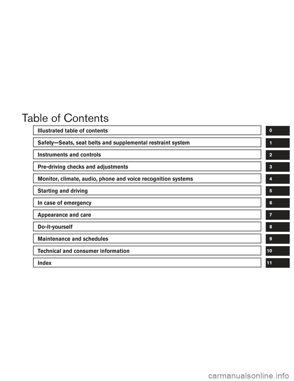
Table of Contents
Illustrated table of contents
Safety—Seats, seat belts and supplemental restraint system
Instruments and controls
Pre-driving checks and adjustments
Monitor, climate, audio, phone and voice recognition systems
Starting and driving
In case of emergency
Appearance and care
Do-it-yourself
Maintenance and schedules
Technical and consumer information
Index
0
1
2
3
4
5
6
7
8
9
10
11
Page 23 of 671
1 Safety—Seats, seat belts and
supplemental restraint system
Seats............................................1-2
Front manual bench seat adjustment
(if so equipped) ................................1-3
Front manual seat adjustment
(if so equipped for passenger’s seat) .............1-4
Front power seat adjustment
(if so equipped) ................................1-5
Front armrests (if so equipped) ...................1-6
Rear armrests (Crew Cab models) ...............1-7
Flexible seating .................................1-7
Head restraints/Headrests ......................... 1-10
Adjustable head restraint/headrest
components .................................. 1-11
Non-adjustable head restraint/headrest
components .................................. 1-12
Remove ...................................... 1-12
Removable (without Dual head restraint/
headrest DVD system only) .....................1-13
Install ........................................ 1-13
Adjust ........................................ 1-13
Seat belts ....................................... 1-15
Precautions on seat belt usage ..................1-15
Seat belt warning light ......................... 1-18
Pregnant women .............................. 1-18Injured persons
................................ 1-18
Three-point type seat belt with retractor ..........1-18
Seat belt extenders ............................ 1-23
Seat belt maintenance ......................... 1-23
Child safety ...................................... 1-24
Infants ........................................ 1-24
Small children ................................. 1-25
Larger children ................................ 1-25
Child restraints ................................... 1-26
Precautions on child restraints ..................1-26
LATCH (Lower Anchors and Tethers for
CHildren) system (Crew Cab models) ...........1-28
Top tether anchor point locations ................1-31
Rear-facing child restraint installation using
LATCH (Crew Cab models) .....................1-31
Rear-facing child restraint installation using
the seat belts (Crew Cab models) . . .............1-33
Rear-facing child restraint installation using
the seat belts (Single Cab models) ..............1-36
Forward-facing
child restraint installation
using LATCH (Crew Cab models) ...............1-36
Forward-facing child restraint installation
using the seat belts — rear bench seat
(Crew Cab models) ............................ 1-39
Page 46 of 671
WARNING
●After adjustment, release the adjust-
ment button and try to move the shoul-
der belt anchor up and down to make
sure it is securely fixed in position.
● The shoulder belt anchor height should
be adjusted to the position best for you.
Failure to do so may reduce the effec-
tiveness of the entire restraint system
and increase the chance or severity of
injury in an accident.
SEAT BELT EXTENDERS
If, because of body size or driving position, it is
not possible to properly fit the lap/shoulder belt
and fasten it, an extender that is compatible with
the installed seat belts is available for purchase.
The extender adds approximately 8 in (200 mm)
of length and may be used for either the driver or
front passenger seating position. It is recom-
mended that you visit a NISSAN dealer for assis-
tance with purchasing an extender if an extender
is required.
WARNING
● Only NISSAN seat belt extenders, made
by the same company which made the
original equipment seat belts, should
be used with NISSAN seat belts.
● Adults and children who can use the
standard seat belt should not use an
extender. Such unnecessary use could
result in serious personal injury in the
event of an accident.
● Never use seat belt extenders to install
child restraints. If the child restraint is
not secured properly, the child could be
seriously injured or killed in a collision
or a sudden stop.
SEAT BELT MAINTENANCE
● To clean the seat belt webbing, apply a
mild soap solution or any solution recom-
mended for cleaning upholstery or carpet.
Then wipe with a cloth and allow the seat
belts to dry in the shade. Do not allow the
seat belts to retract until they are completely
dry. ●
If dirt builds up in the shoulder belt
guide of the seat belt anchors, the seat
belts may retract slowly. Wipe the shoulder
belt guide with a clean, dry cloth.
● Periodically check to see that the seat
belt and the metal components, such as
buckles, tongues, retractors, flexible wires
and anchors, work properly. If loose parts,
deterioration, cuts or other damage on the
webbing is found, the entire seat belt as-
sembly should be replaced.
Safety—Seats, seat belts and supplemental restraint system1-23
Page 101 of 671
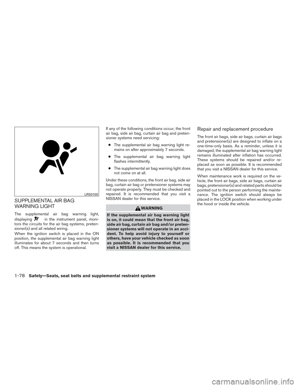
SUPPLEMENTAL AIR BAG
WARNING LIGHT
The supplemental air bag warning light,
displaying
in the instrument panel, moni-
tors the circuits for the air bag systems, preten-
sioner(s) and all related wiring.
When the ignition switch is placed in the ON
position, the supplemental air bag warning light
illuminates for about 7 seconds and then turns
off. This means the system is operational. If any of the following conditions occur, the front
air bag, side air bag, curtain air bag and preten-
sioner systems need servicing:
● The supplemental air bag warning light re-
mains on after approximately 7 seconds.
● The supplemental air bag warning light
flashes intermittently.
● The supplemental air bag warning light does
not come on at all.
Under these conditions, the front air bag, side air
bag, curtain air bag or pretensioner systems may
not operate properly. They must be checked and
repaired. It is recommended that you visit a
NISSAN dealer for this service.
WARNING
If the supplemental air bag warning light
is on, it could mean that the front air bag,
side air bag, curtain air bag and/or preten-
sioner systems will not operate in an acci-
dent. To help avoid injury to yourself or
others, have your vehicle checked as soon
as possible. It is recommended that you
visit a NISSAN dealer for this service.
Repair and replacement procedure
The front air bags, side air bags, curtain air bags
and pretensioner(s) are designed to inflate on a
one-time-only basis. As a reminder, unless it is
damaged, the supplemental air bag warning light
remains illuminated after inflation has occurred.
These systems should be repaired and/or re-
placed as soon as possible. It is recommended
that you visit a NISSAN dealer for this service.
When maintenance work is required on the ve-
hicle, the front air bags, side air bags, curtain air
bags, pretensioner(s) and related parts should be
pointed out to the person performing the mainte-
nance. The ignition switch should always be
placed in the LOCK position when working under
the hood or inside the vehicle.
LRS0100
1-78Safety—Seats, seat belts and supplemental restraint system
Page 118 of 671
Time
The time mode shows the time the vehicle has
been on since the last reset. The displayed time
can be reset by pressing the ENTER button on
the steering wheel for more than approximately
1 second.
Tire info
The tire info mode shows the pressure of each
tire. To see the individual tire pressures, press the
ENTER button when the desired tire is shown.
The tire pressures are displayed as follows:● FL (Front Left)
● FR (Front Right)
● RL (Rear Left)
● RR (Rear Right)
To return to the main menu selections, scroll to
“EXIT” and press ENTER.
Settings
The settings mode allows the user to change the
trip computer display units and set maintenance
reminders. To select the desired menu item,
press the ENTER button when it is shown. The
menu items are displayed as follows:
● Engine Oil
● Oil Filter
● Rotation
● Other
● Units
LIC3507LIC3508LIC3509
Instruments and controls2-15
Page 119 of 671
To return to the main menu selections, scroll to
“EXIT” and press ENTER.
Engine oil
The engine oil menu item allows the user to set a
maintenance reminder at a specific interval. To
set the reminder, press the ENTER button when
“ENGINE OIL” is shown. Using the
but-
tons, set the desired interval to receive a mainte-
nance reminder.
To reset the mileage, press and hold the ENTER
button for approximately 1 second.
To return to the main menu selections, scroll to
“EXIT” and press ENTER.
For additional information, refer to “Maintenance
schedules” in the “Maintenance and schedules”
section of this manual.
Oil filter
The oil filter menu item allows the user to set a
maintenance reminder at a specific interval. To
set the reminder, press the ENTER button when
“OIL FILTER” is shown. Using the
but-
tons, set the desired interval to receive a mainte-
nance reminder.
To reset the mileage, press and hold the ENTER
button for approximately 1 second.
To return to the main menu selections, scroll to
“EXIT” and press ENTER. For additional information, refer to “Maintenance
schedules” in the “Maintenance and schedules”
section of this manual.
Rotation
The rotation menu item allows the user to set a
maintenance reminder at a specific interval. To
set the reminder, press the ENTER button when
“ROTATION” is shown. Using the
but-
tons, set the desired interval to receive a mainte-
nance reminder.
To reset the mileage, press and hold the ENTER
button for approximately 1 second.
To return to the main menu selections, scroll to
“EXIT” and press ENTER.
For additional information, refer to “Maintenance
schedules” in the “Maintenance and schedules”
section of this manual.
WARNING
The tire replacement indicator is not a
substitute for regular tire checks, includ-
ing tire pressure checks. For additional
information, refer to “Changing wheels
and tires” in the “Do-it-yourself” section of
this manual. Many factors including tire
inflation, alignment, driving habits and
road conditions affect tire wear and when
tires should be replaced. Setting the tire
replacement indicator for a certain driving
distance does not mean your tires will last
that long. Use the tire replacement indica-
tor as a guide only and always perform
regular tire checks. Failure to perform
regular tire checks, including tire pressure
checks could result in tire failure. Serious
vehicle damage could occur and may lead
to a collision, which could result in serious
personal injury or death.
Other
The other menu item allows the user to set a
maintenance reminder at a specific interval to
check various other maintenance items (ie. air
filter, brakes, coolant) . To set the reminder, press
the ENTER button when “OTHER” is shown.
Using the
buttons, set the desired inter-
val to receive a maintenance reminder.
2-16Instruments and controls
Page 120 of 671
To reset the mileage, press and hold the ENTER
button for approximately 1 second.
To return to the main menu selections, scroll to
“EXIT” and press ENTER.
For additional information, refer to “Maintenance
schedules” in the “Maintenance and schedules”
section of this manual.
Units
The units menu item allows the user to change
the trip computer units to US or METRIC. To
select the units, press the ENTER button when
desired unit is shown.
To return to the main menu selections, scroll to
“EXIT” and press ENTER.
4WD error
The “4WD ERROR” message appears in the
center of the trip computer when there is a mal-
function with the 4–wheel drive system. For ad-
ditional information, refer to “4–Wheel Drive
(4WD) warning light” in this section.
4WD tires
The “4WD TIRES” message appears in the cen-
ter of the trip computer when there is a large
difference in wheel rotation. If this messages
appears, switch the vehicle into 2WD mode. For
additional information, refer to “Using 4–Wheel
Drive (4WD)” in the “Starting and driving” section
of this manual.
LIC3544LIC3545
Instruments and controls2-17
Page 133 of 671
Malfunction Indicator Light(MIL) (yellow) (For Gas
engines only)
If this indicator light comes on steady or blinks
while the engine is running, it may indicate a
potential emission control malfunction.
If this indicator light comes on steady for 20 sec-
onds and then blinks for 10 seconds when the
engine is not running, it indicates that the vehicle
is not ready for an emission control system
inspection/maintenance test. For additional infor-
mation, refer to “Readiness for
inspection/maintenance (I/M) test” in the “Tech-
nical and consumer information” section of this
manual. Operation
The MIL will come on in one of two ways:
● MIL on steady — An emission control system
malfunction has been detected. Check the
fuel-filler cap. If the LOOSE FUEL CAP
warning message (if so equipped) is dis-
played in the odometer, and the fuel-filler
cap is loose or missing, tighten or install the
cap and continue to drive the vehicle.
The
light should turn off after a few
driving trips. If the
light does not turn
off after a few driving trips, have the vehicle
inspected. It is recommended that you visit a
NISSAN dealer for this service. You do not
need to have your vehicle towed to the
dealer.
● MIL blinking — An engine misfire has been
detected which may damage the emission
control system. To reduce or avoid emission
control system damage:
– do not drive at speeds above 45 mph (72 km/h);
– avoid hard acceleration or deceleration;
– avoid steep uphill grades;
– if possible, reduce the amount of cargo being hauled. The MIL may stop blinking and come on steady.
Have the vehicle inspected. It is recommended
that you visit a NISSAN dealer for this service.
You do not need to have your vehicle towed to the
dealer.
CAUTION
Continued vehicle operation without hav-
ing the emission control system checked
and repaired as necessary could lead to
poor driveability, reduced fuel economy,
and possible damage to the emission con-
trol system.
Security indicator light
This light blinks whenever the ignition switch is
placed in the LOCK, OFF or ACC position. This
function indicates the security system equipped
on the vehicle is operational.
For additional information, refer to “Security sys-
tems” in this section.
2-30Instruments and controls