brake sensor NISSAN TITAN 2020 Owner´s Manual
[x] Cancel search | Manufacturer: NISSAN, Model Year: 2020, Model line: TITAN, Model: NISSAN TITAN 2020Pages: 657, PDF Size: 5.1 MB
Page 131 of 657
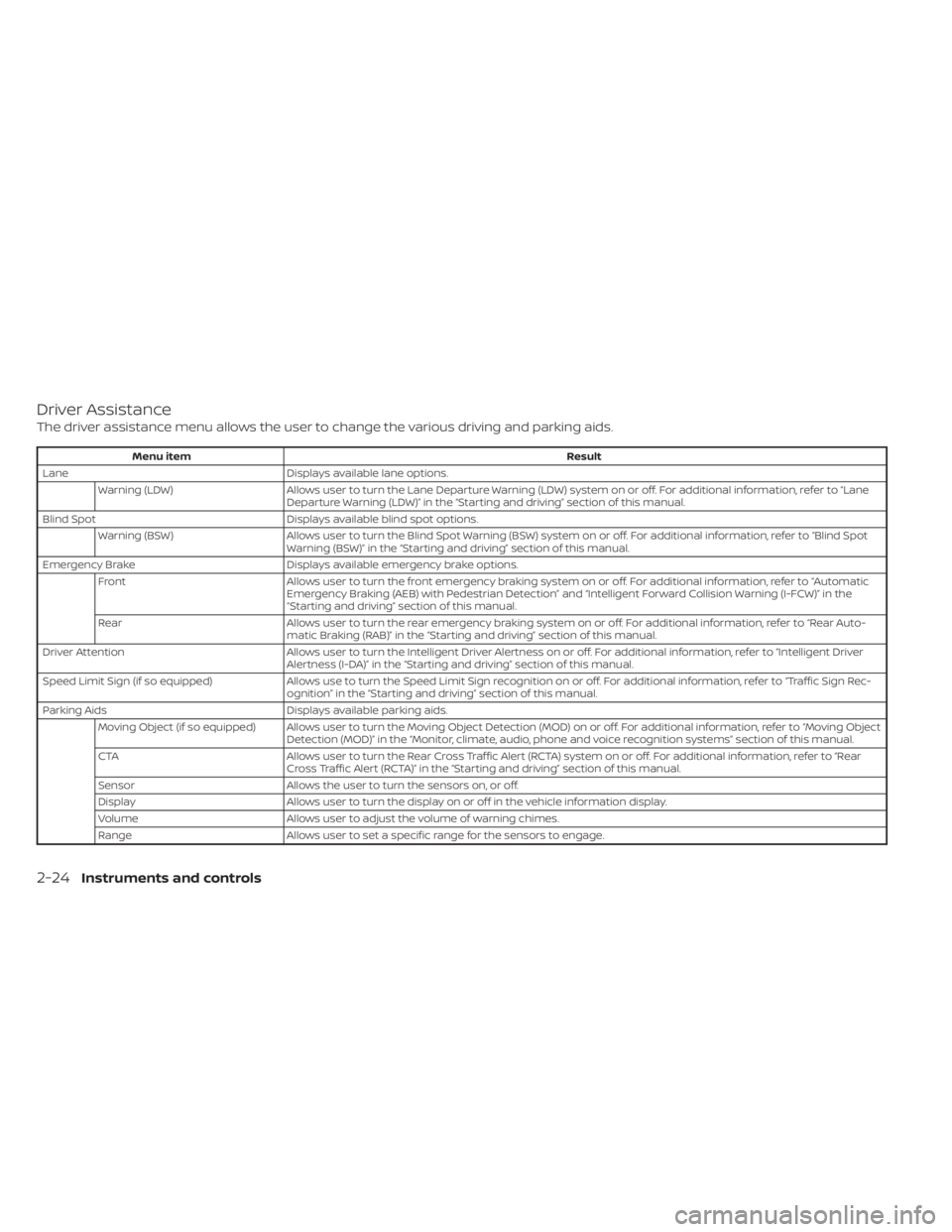
Driver Assistance
The driver assistance menu allows the user to change the various driving and parking aids.
Menu itemResult
Lane Displays available lane options.
Warning (LDW) Allows user to turn the Lane Departure Warning (LDW) system on or off. For additional information, refer to “Lane
Departure Warning (LDW)” in the “Starting and driving” section of this manual.
Blind Spot Displays available blind spot options.
Warning (BSW) Allows user to turn the Blind Spot Warning (BSW) system on or off. For additional information, refer to “Blind Spot
Warning (BSW)” in the “Starting and driving” section of this manual.
Emergency Brake Displays available emergency brake options.
Front Allows user to turn the front emergency braking system on or off. For additional information, refer to “Automatic
Emergency Braking (AEB) with Pedestrian Detection” and “Intelligent Forward Collision Warning (I-FCW)” in the
“Starting and driving” section of this manual.
Rear Allows user to turn the rear emergency braking system on or off. For additional information, refer to “Rear Auto-
matic Braking (RAB)” in the “Starting and driving” section of this manual.
Driver Attention Allows user to turn the Intelligent Driver Alertness on or off. For additional information, refer to “Intelligent Driver
Alertness (I-DA)” in the “Starting and driving” section of this manual.
Speed Limit Sign (if so equipped) Allows use to turn the Speed Limit Sign recognition on or off. For additional information, refer to “Traffic Sign Rec-
ognition” in the “Starting and driving” section of this manual.
Parking Aids Displays available parking aids.
Moving Object (if so equipped) Allows user to turn the Moving Object Detection (MOD) on or off. For additional information, refer to “Moving Object Detection (MOD)” in the “Monitor, climate, audio, phone and voice recognition systems” section of this manual.
CTA Allows user to turn the Rear Cross Traffic Alert (RCTA) system on or off. For additional information, refer to “Rear
Cross Traffic Alert (RCTA)” in the “Starting and driving” section of this manual.
Sensor Allows the user to turn the sensors on, or off.
Display Allows user to turn the display on or off in the vehicle information display.
Volume Allows user to adjust the volume of warning chimes.
Range Allows user to set a specific range for the sensors to engage.
2-24Instruments and controls
Page 140 of 657
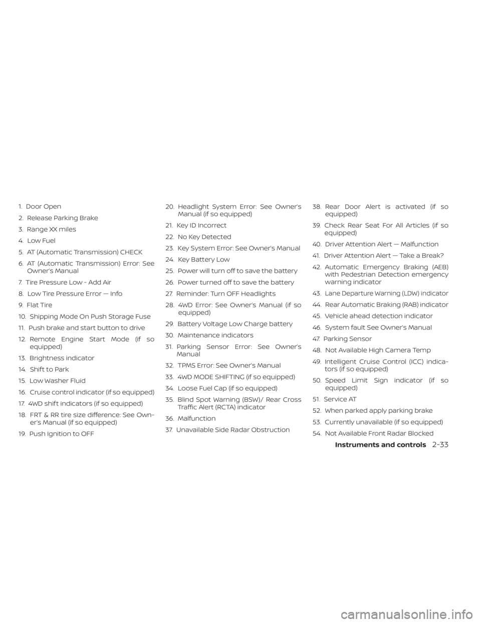
1. Door Open
2. Release Parking Brake
3. Range XX miles
4. Low Fuel
5. AT (Automatic Transmission) CHECK
6. AT (Automatic Transmission) Error: SeeOwner’s Manual
7. Tire Pressure Low - Add Air
8. Low Tire Pressure Error — Info
9. Flat Tire
10. Shipping Mode On Push Storage Fuse
11. Push brake and start button to drive
12. Remote Engine Start Mode (if so equipped)
13. Brightness indicator
14. Shif t to Park
15. Low Washer Fluid
16. Cruise control indicator (if so equipped)
17. 4WD shif t indicators (if so equipped)
18. FRT & RR tire size difference: See Own- er’s Manual (if so equipped)
19. Push Ignition to OFF 20. Headlight System Error: See Owner’s
Manual (if so equipped)
21. Key ID Incorrect
22. No Key Detected
23. Key System Error: See Owner’s Manual
24. Key Battery Low
25. Power will turn off to save the battery
26. Power turned off to save the battery
27. Reminder: Turn OFF Headlights
28. 4WD Error: See Owner’s Manual (if so equipped)
29. Battery Voltage Low Charge battery
30. Maintenance indicators
31. Parking Sensor Error: See Owner’s Manual
32. TPMS Error: See Owner’s Manual
33. 4WD MODE SHIFTING (if so equipped)
34. Loose Fuel Cap (if so equipped)
35. Blind Spot Warning (BSW)/ Rear Cross Traffic Alert (RCTA) indicator
36. Malfunction
37. Unavailable Side Radar Obstruction 38. Rear Door Alert is activated (if so
equipped)
39. Check Rear Seat For All Articles (if so equipped)
40. Driver Attention Alert — Malfunction
41. Driver Attention Alert — Take a Break?
42. Automatic Emergency Braking (AEB) with Pedestrian Detection emergency
warning indicator
43.
Lane Departure Warning (LDW) indicator
44. Rear Automatic Braking (RAB) indicator
45. Vehicle ahead detection indicator
46. System fault See Owner’s Manual
47. Parking Sensor
48. Not Available High Camera Temp
49. Intelligent Cruise Control (ICC) indica- tors (if so equipped)
50. Speed Limit Sign indicator (if so equipped)
51. Service AT
52. When parked apply parking brake
53. Currently unavailable (if so equipped)
54. Not Available Front Radar Blocked
Instruments and controls2-33
Page 146 of 657
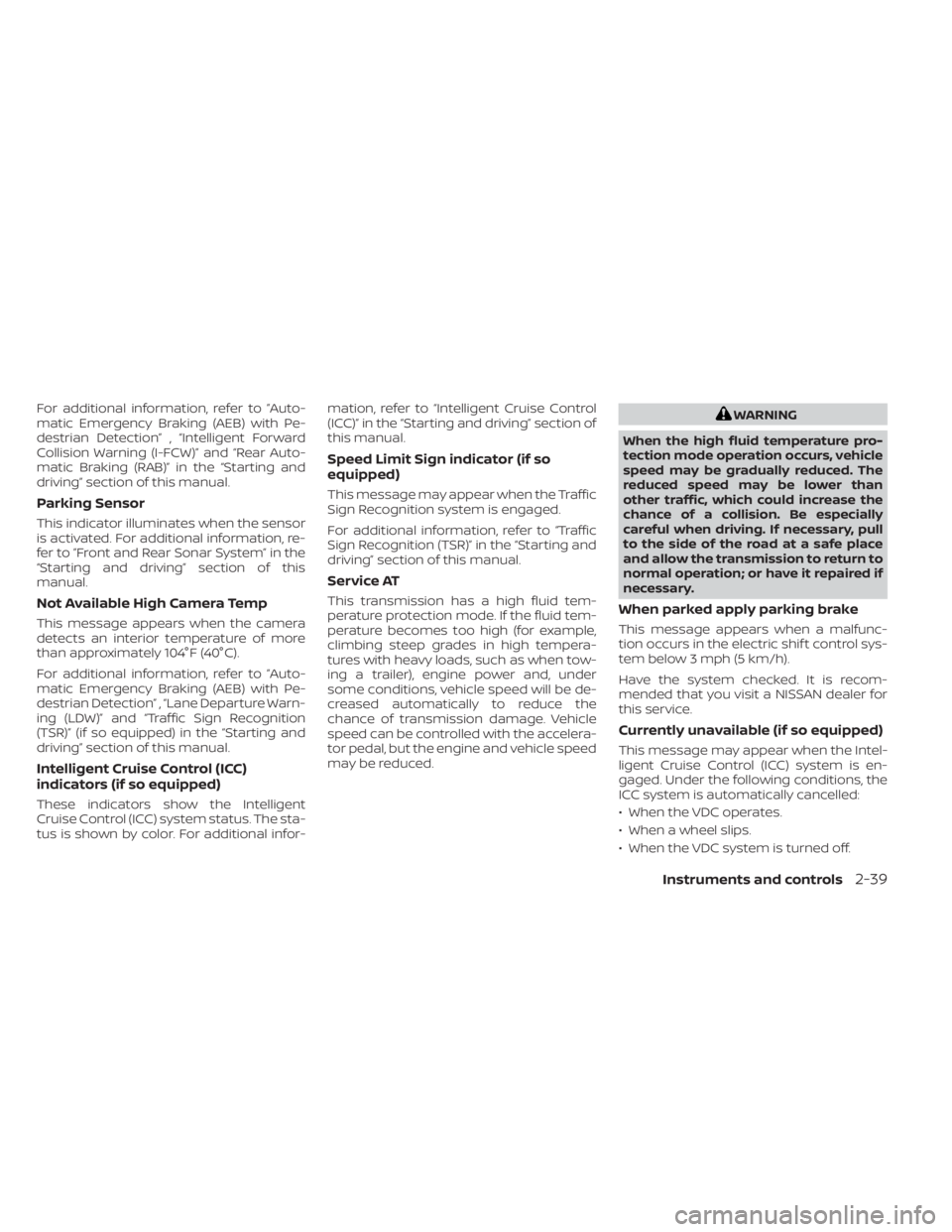
For additional information, refer to ”Auto-
matic Emergency Braking (AEB) with Pe-
destrian Detection” , “Intelligent Forward
Collision Warning (I-FCW)” and “Rear Auto-
matic Braking (RAB)” in the “Starting and
driving” section of this manual.
Parking Sensor
This indicator illuminates when the sensor
is activated. For additional information, re-
fer to ”Front and Rear Sonar System” in the
“Starting and driving” section of this
manual.
Not Available High Camera Temp
This message appears when the camera
detects an interior temperature of more
than approximately 104°F (40°C).
For additional information, refer to ”Auto-
matic Emergency Braking (AEB) with Pe-
destrian Detection” , “Lane Departure Warn-
ing (LDW)” and “Traffic Sign Recognition
(TSR)” (if so equipped) in the “Starting and
driving” section of this manual.
Intelligent Cruise Control (ICC)
indicators (if so equipped)
These indicators show the Intelligent
Cruise Control (ICC) system status. The sta-
tus is shown by color. For additional infor-mation, refer to “Intelligent Cruise Control
(ICC)” in the “Starting and driving” section of
this manual.
Speed Limit Sign indicator (if so
equipped)
This message may appear when the Traffic
Sign Recognition system is engaged.
For additional information, refer to “Traffic
Sign Recognition (TSR)” in the “Starting and
driving” section of this manual.
Service AT
This transmission has a high fluid tem-
perature protection mode. If the fluid tem-
perature becomes too high (for example,
climbing steep grades in high tempera-
tures with heavy loads, such as when tow-
ing a trailer), engine power and, under
some conditions, vehicle speed will be de-
creased automatically to reduce the
chance of transmission damage. Vehicle
speed can be controlled with the accelera-
tor pedal, but the engine and vehicle speed
may be reduced.
WARNING
When the high fluid temperature pro-
tection mode operation occurs, vehicle
speed may be gradually reduced. The
reduced speed may be lower than
other traffic, which could increase the
chance of a collision. Be especially
careful when driving. If necessary, pull
to the side of the road at a safe place
and allow the transmission to return to
normal operation; or have it repaired if
necessary.
When parked apply parking brake
This message appears when a malfunc-
tion occurs in the electric shif t control sys-
tem below 3 mph (5 km/h).
Have the system checked. It is recom-
mended that you visit a NISSAN dealer for
this service.
Currently unavailable (if so equipped)
This message may appear when the Intel-
ligent Cruise Control (ICC) system is en-
gaged. Under the following conditions, the
ICC system is automatically cancelled:
• When the VDC operates.
• When a wheel slips.
• When the VDC system is turned off.
Instruments and controls2-39
Page 159 of 657
If the ambient image sensor is damaged
due to an accident, it is recommended that
you visit a NISSAN dealer.
Battery saver system
If the ignition switch is placed in the OFF
position while the headlight switch is in the
orposition, the headlights will
turn off af ter a period of time.
Af ter the headlights automatically turn off
with the headlight switch in the
orposition, the headlights will illuminate
again if the headlight switch is moved to
the OFF position and then turned to the
orposition.
CAUTION
Even though the battery saver feature
automatically turns off the headlights
af ter a period of time, you should turn
the headlight switch to the OFF posi-
tion when the engine is not running to
avoid discharging the vehicle battery.
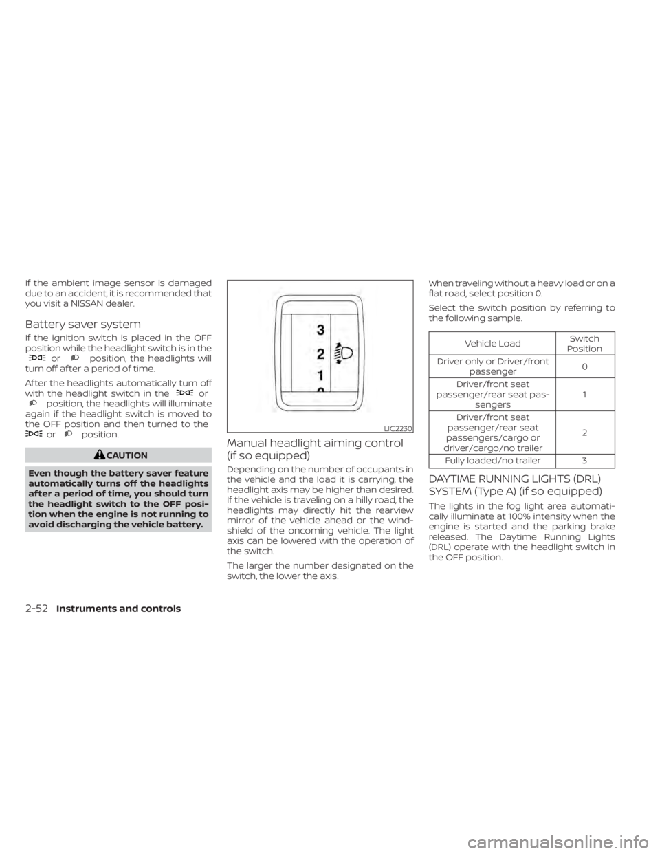
Manual headlight aiming control
(if so equipped)
Depending on the number of occupants in
the vehicle and the load it is carrying, the
headlight axis may be higher than desired.
If the vehicle is traveling on a hilly road, the
headlights may directly hit the rearview
mirror of the vehicle ahead or the wind-
shield of the oncoming vehicle. The light
axis can be lowered with the operation of
the switch.
The larger the number designated on the
switch, the lower the axis. When traveling without a heavy load or on a
flat road, select position 0.
Select the switch position by referring to
the following sample.
Vehicle Load
Switch
Position
Driver only or Driver/front passenger 0
Driver/front seat
passenger/rear seat pas- sengers 1
Driver/front seat
passenger/rear seat
passengers/cargo or
driver/cargo/no trailer 2
Fully loaded/no trailer 3
DAYTIME RUNNING LIGHTS (DRL)
SYSTEM (Type A) (if so equipped)
The lights in the fog light area automati-
cally illuminate at 100% intensity when the
engine is started and the parking brake
released. The Daytime Running Lights
(DRL) operate with the headlight switch in
the OFF position.
LIC2230
2-52Instruments and controls
Page 341 of 657
When adding air to an under-inflated tire,
the TPMS with Easy-Fill Tire Alert provides
visual and audible signals outside the ve-
hicle to help you inflate the tires to the rec-
ommended COLD tire pressure.
Vehicle set-up
1. Park the vehicle in a safe and level place.
2. Apply the parking brake and place theshif t lever in the P (Park) position.
3. Place the ignition switch in the ON posi- tion. Do not start the engine.
Operation
1. Add air to the tire.
2. Af ter a few seconds, the hazard indica- tors will start flashing.
3. When the designated pressure is reached, the horn beeps once and the
hazard indicators stop flashing.
4. Perform the above steps for each tire. • If the tire is over-inflated more thanapproximately 4 psi (30 kPa), the horn
beeps and the hazard indicators flash
three times. To correct the pressure,
push the core of the valve stem on the
tire briefly to release pressure. When
the pressure reaches the designated
pressure, the horn beeps once. • If the hazard indicator does not flash
within approximately 15 seconds af ter
starting to inflate the tire, it indicates
that the Easy-Fill Tire Alert is not oper-
ating.
• The TPMS will not activate the Easy-Fill Tire Alert under the following condi-
tions:– If there is interference from an exter- nal device or transmitter.
– The air pressure from the inflation device is not sufficient to inflate the
tire.
– There is a malfunction in the TPMS.
– There is a malfunction in the horn or hazard indicators.
– The identification code of the tire pressure sensor is not registered to
the system.
– The battery of the tire pressure sen- sor is low.
• If the Easy-Fill Tire Alert does not oper- ate due to TPMS interference, move
the vehicle about 3 f t (1 m) backward
or forward and try again.
If the Easy-Fill Tire Alert is not working, use a
tire pressure gauge.ON-PAVEMENT AND OFF-ROAD
DRIVING PRECAUTIONS
Utility vehicles have a significantly
higher rollover rate than other types of
vehicles.
They have higher ground clearance than
passenger cars to make them capable of
performing in a variety of on-pavement
and off-road applications. This gives them
a higher center of gravity than ordinary ve-
hicles. An advantage of higher ground
clearance is a better view of the road, allow-
ing you to anticipate problems. However,
they are not designed for cornering at the
same speeds as conventional 2-Wheel
Drive vehicles any more than low-slung
sports cars are designed to perform satis-
factorily under off-road conditions. If at all
possible, avoid sharp turns at high speeds.
As with other vehicles of this type, failure to
operate this vehicle correctly may result in
loss of control or vehicle rollover. In a roll-
over crash, an unbelted person is signifi-
cantly more likely to die than a person
wearing a seat belt.
For additional information, refer to “Driving
safety precautions” in this section.
5-8Starting and driving
Page 387 of 657
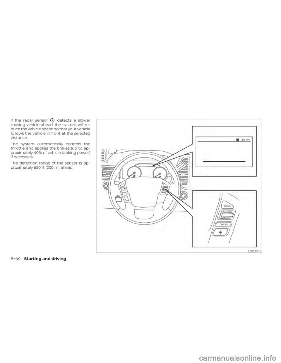
If the radar sensorO1detects a slower
moving vehicle ahead, the system will re-
duce the vehicle speed so that your vehicle
follows the vehicle in front at the selected
distance.
The system automatically controls the
throttle and applies the brakes (up to ap-
proximately 40% of vehicle braking power)
if necessary.
The detection range of the sensor is ap-
proximately 650 f t (200 m) ahead.
LSD3760
5-54Starting and driving
Page 395 of 657
Approach warning
If your vehicle comes closer to the vehicle
ahead due to rapid deceleration of that ve-
hicle or if another vehicle cuts in, the sys-
tem warns the driver with the chime and
ICC system display. Decelerate by depress-
ing the brake pedal to maintain a safe ve-
hicle distance if:
• The chime sounds.
• The vehicle ahead detection indicatorblinks.
The warning chime may not sound in
some cases when there is a short distance
between vehicles. Some examples are:
• When the vehicles are traveling at the same speed and the distance between
vehicles is not changing.
• When the vehicle ahead is traveling faster and the distance between vehicles is in-
creasing.
• When a vehicle cuts in near your vehicle.
The warning chime will not sound when:
• The vehicle approaches other vehicles that are parked or moving slowly.
• The accelerator pedal is depressed, over- riding the system.
NOTE:
The approach warning chime may sound
and the system display may blink when
the ICC sensor detects objects on the
side of the vehicle or on the side of the
road. This may cause the ICC system to
decelerate or accelerate the vehicle. The
ICC sensor may detect these objects
when the vehicle is driven on winding
roads, narrow roads, hilly roads, or when
entering or exiting a curve. In these
cases you will have to manually control
the proper distance ahead of your
vehicle.
Also, the sensor sensitivity can be affected
by vehicle operation (steering maneuver or
driving position in the lane) or traffic or ve-
hicle condition (for example, if a vehicle is
being driven with some damage).
Acceleration when passing
When the ICC system is engaged above 37
mph and following a slower vehicle (below
ICC set speed), and the turn signal is acti-
vated to the lef t, the ICC system will auto-
matically start to accelerate the vehicle to
help initiate passing on the lef t and will begin
to reduce the distance to vehicle directly
ahead. Only the lef t side turn signal operates
this feature. As the driver steers the vehicle and moves into the passing lane, if no vehicle
is detected ahead the ICC system will con-
tinue to accelerate to the ICC system set
speed. If another vehicle is detected ahead,
then the vehicle will accelerate up to the fol-
lowing speed of that vehicle. If the vehicle is
not steered into the lef t lane to pass, the
acceleration will stop af ter a short time and
regain the set following distance. Accelera-
tion can be stopped at any point by depress-
ing the brake pedal or the CANCEL switch on
the steering wheel.
WARNING
In order to reduce the risk of a collision
that may result in serious injury or
death, please be aware of the following:
• This function is only activated with
the lef t turn signal and will briefly ac-
celerate the vehicle even if a lane
change is not initiated. This can in-
clude non-passing situations such as
lef t side exits.
• Ensure that when passing another
vehicle, the adjacent lane is clear be-
fore initiating the pass. Sudden
changes in traffic may occur while
passing — always manually steer or
brake as needed — never solely rely
on the system.
5-62Starting and driving
Page 396 of 657
Automatic cancellation
A chime sounds under the following condi-
tions and the control is automatically can-
celed:
• When the vehicle ahead is not detectedand your vehicle is traveling below the
speed of 15 mph (24 km/h)
• When the system judges the vehicle is at a standstill
• When the shif t lever is not in the D (Drive) position, Manual mode or L (Low) range.
• When the parking brake system is applied
• When the VDC system is turned off
• When VDC operates
• When distance measurement becomes impaired due to adhesion of dirt or ob-
struction to the sensor
• When a wheel slips
• When the radar signal is temporarily in- terrupted
VEHICLE-TO-VEHICLE DISTANCE
CONTROL MODE LIMITATIONS
WARNING
Listed below are the system limitations
for the ICC system. Failure to operate
the vehicle in accordance with these
system limitations could result in seri-
ous injury or death.
• The ICC system is primarily intended
for use on straight, dry, open roads
with light traffic. It is not advisable to
use the ICC system in city traffic or
congested areas.
• The ICC system will not adapt auto-
matically to road conditions. This
system should be used in evenly
flowing traffic. Do not use the system
on roads with sharp curves, or on icy
roads, in heavy rain or in fog.
•
As there is a performance limit to the
distance control function, never rely
solely on the ICC system. This system
does not correct careless, inattentive
or absentminded driving, or overcome
poor visibility in rain, fog, or other bad
weather. Decelerate the vehicle speed
by depressing the brake pedal, de-
pending on the distance to the vehicle ahead and the surrounding circum-
stances in order to maintain a safe dis-
tance between vehicles.
•
If the vehicle ahead comes to a stop,
the vehicle decelerates to a standstill
within the limitations of the system.
The system will cancel once it judges
that the vehicle has come to a stand-
still and sound a warning chime. To
prevent the vehicle from moving, the
driver must depress the brake pedal.
• Always pay attention to the opera-
tion of the vehicle and be ready to
manually control the proper follow-
ing distance. The ICC system may not
be able to maintain the selected dis-
tance between vehicles (following
distance) or selected vehicle speed
under some circumstances.
• The system may not detect the ve-
hicle in front of you in certain road or
weather conditions. To avoid acci-
dents, never use the ICC system un-
der the following conditions: – On roads where the traffic is heavy
or there are sharp curves
– On slippery road surfaces such as
on ice or snow, etc.
– During bad weather (rain, fog,
snow, etc.)
Starting and driving5-63
Page 397 of 657
–When rain, snow or dirt adhere to
the bumper around the distance
sensor
– On steep downhill roads (the ve-
hicle may go beyond the set ve-
hicle speed and frequent braking
may result in overheating the
brakes)
– On repeated uphill and downhill
roads
– When traffic conditions make it
difficult to keep a proper distance
between vehicles because of fre-
quent acceleration or
deceleration
– Interference by other radar
sources
• Do not use the ICC system if you are
towing a trailer. The system may not
detect a vehicle ahead.
• In some road or traffic conditions, a
vehicle or object can unexpectedly
come into the sensor detection zone
and cause automatic braking. Al-
ways stay alert and avoid using the
ICC system where not recommended
in this warning section. The radar sensor will not detect the follow-
ing objects:
• Stationary and slow moving vehicles
• Pedestrians or objects in the roadway
• Oncoming vehicles in the same lane
• Motorcycles traveling offset in the travel
lane
The sensor generally detects the signals
returned from the vehicle ahead. Therefore,
if the sensor cannot detect the reflection
from the vehicle ahead, the ICC system
may not maintain the selected distance.
The following are some conditions in which
the sensor cannot properly detect a ve-
hicle ahead and the system may not oper-
ate properly:
• When snow or road spray from traveling vehicles reduces the sensor’s detection.
• When your vehicle is towing a trailer, etc.
• When excessively heavy baggage is loaded in the rear seat or cargo area of
your vehicle.
The ICC system is designed to automati-
cally check the sensor’s operation within
the limitations of the system.
When the sensor is covered with dirt or is
obstructed, the system will automatically
be canceled. If the sensor is covered with ice, a transparent or translucent vinyl bag,
etc., the ICC system may not detect them.
In these instances, the vehicle-to-vehicle
distance control mode may not cancel and
may not be able to maintain the selected
following distance from the vehicle ahead.
Be sure to check and clean the sensor
regularly.
The detection zone of the radar sensor is
limited. A vehicle ahead must be in the de-
tection zone for the vehicle-to-vehicle dis-
tance detection mode to maintain the se-
lected distance from the vehicle ahead.
A vehicle ahead may move outside of the
detection zone due to its position within
the same lane of travel. Motorcycles may
not be detected in the same lane ahead if
they are traveling offset from the centerline
of the lane. A vehicle that is entering the
lane ahead may not be detected until the
vehicle has completely moved into the
lane.
If this occurs, the ICC system may warn
you by blinking the system indicator and
sounding the chime. The driver may
have to manually control the proper dis-
tance away from vehicle traveling ahead.
5-64Starting and driving
Page 411 of 657

RAB SYSTEM LIMITATIONS
WARNING
Listed below are the system limitations
for the RAB system. Failure to follow the
warnings and instructions for proper
use of the RAB system could result in
serious injury or death.
• When the vehicle approaches an ob-
stacle while the accelerator or brake
pedal is depressed, the function may
not operate or the start of operation
may be delayed. The RAB system
may not operate or may not perform
sufficiently due to vehicle conditions,
driving conditions, the traffic envi-
ronment, the weather, road surface
conditions, etc. Do not wait for the
system to operate. Operate the brake
pedal by yourself as soon as
necessary.
• If it is necessary to override RAB op-
eration, strongly press the accelera-
tor pedal. •
Always check your surroundings and
turn to check what is behind you be-
fore and while backing up. The RAB
system detects stationary objects
behind the vehicle. The RAB system
does not detect the following ob-
jects:
– Moving objects
– Low objects
– Narrow objects
– Wedge-shaped objects
– Objects close to the bumper (less
than approximately 1 f t [30 cm])
– Objects that suddenly appear
– Thin objects such as rope, wire,
chain, etc.
• The RAB system may not operate for
the following obstacles:
– Obstacles located high off the
ground
– Obstacles in a position offset from
your vehicle
– Obstacles, such as spongy materi-
als or snow, that have sof t outer
surfaces and can easily absorb a
sound wave •
The RAB system may not operate in
the following conditions:
– There is rain, snow, ice, dirt, etc.,
attached to the sonar sensors.
– A loud sound is heard in the area
around the vehicle.
– The surface of the obstacle is di-
agonal to the rear of the vehicle.
• The RAB system may unintentionally
operate in the following conditions:
– There is overgrown grass in the
area around the vehicle.
– When you are towing a trailer etc.
– There is a structure (e.g., a wall, toll
gate equipment, a narrow tunnel,
a parking lot gate) near the side of
the vehicle.
– There are bumps, protrusions, or
manhole covers on the road
surface.
– The vehicle drives through a
draped flag or a curtain.
– There is an accumulation of snow
or ice behind the vehicle.
– An ultrasonic wave source, such as
another vehicle’s sonar, is near
the vehicle.
5-78Starting and driving