driver seat adjustment NISSAN TITAN 2023 Owners Manual
[x] Cancel search | Manufacturer: NISSAN, Model Year: 2023, Model line: TITAN, Model: NISSAN TITAN 2023Pages: 644, PDF Size: 7.8 MB
Page 22 of 644
WARNING
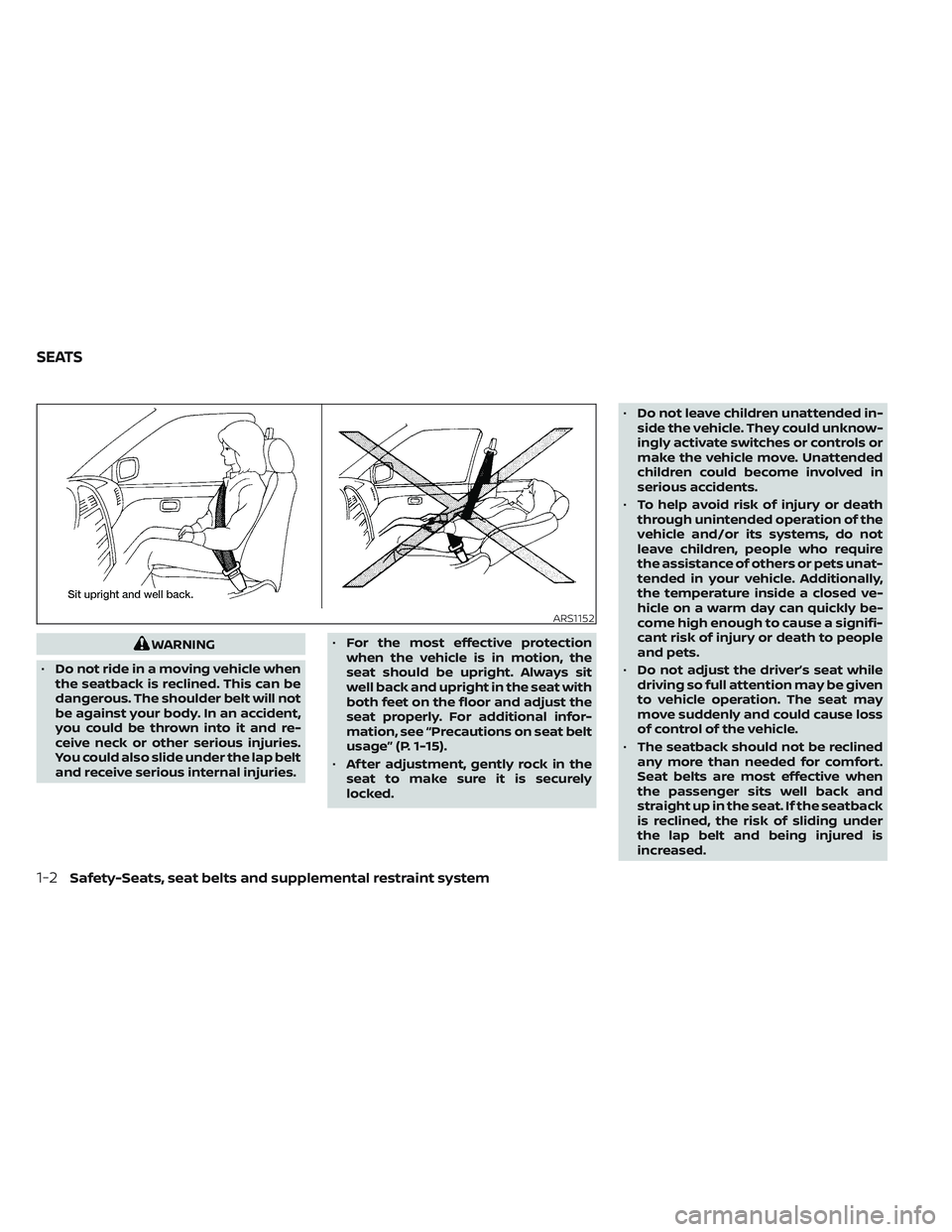
• Do not ride in a moving vehicle when
the seatback is reclined. This can be
dangerous. The shoulder belt will not
be against your body. In an accident,
you could be thrown into it and re-
ceive neck or other serious injuries.
You could also slide under the lap belt
and receive serious internal injuries. •
For the most effective protection
when the vehicle is in motion, the
seat should be upright. Always sit
well back and upright in the seat with
both feet on the floor and adjust the
seat properly. For additional infor-
mation, see “Precautions on seat belt
usage” (P. 1-15).
• Af ter adjustment, gently rock in the
seat to make sure it is securely
locked. •
Do not leave children unattended in-
side the vehicle. They could unknow-
ingly activate switches or controls or
make the vehicle move. Unattended
children could become involved in
serious accidents.
• To help avoid risk of injury or death
through unintended operation of the
vehicle and/or its systems, do not
leave children, people who require
the assistance of others or pets unat-
tended in your vehicle. Additionally,
the temperature inside a closed ve-
hicle on a warm day can quickly be-
come high enough to cause a signifi-
cant risk of injury or death to people
and pets.
• Do not adjust the driver’s seat while
driving so full attention may be given
to vehicle operation. The seat may
move suddenly and could cause loss
of control of the vehicle.
• The seatback should not be reclined
any more than needed for comfort.
Seat belts are most effective when
the passenger sits well back and
straight up in the seat. If the seatback
is reclined, the risk of sliding under
the lap belt and being injured is
increased.
ARS1152
SEATS
1-2Safety-Seats, seat belts and supplemental restraint system
Page 26 of 644
Reclining
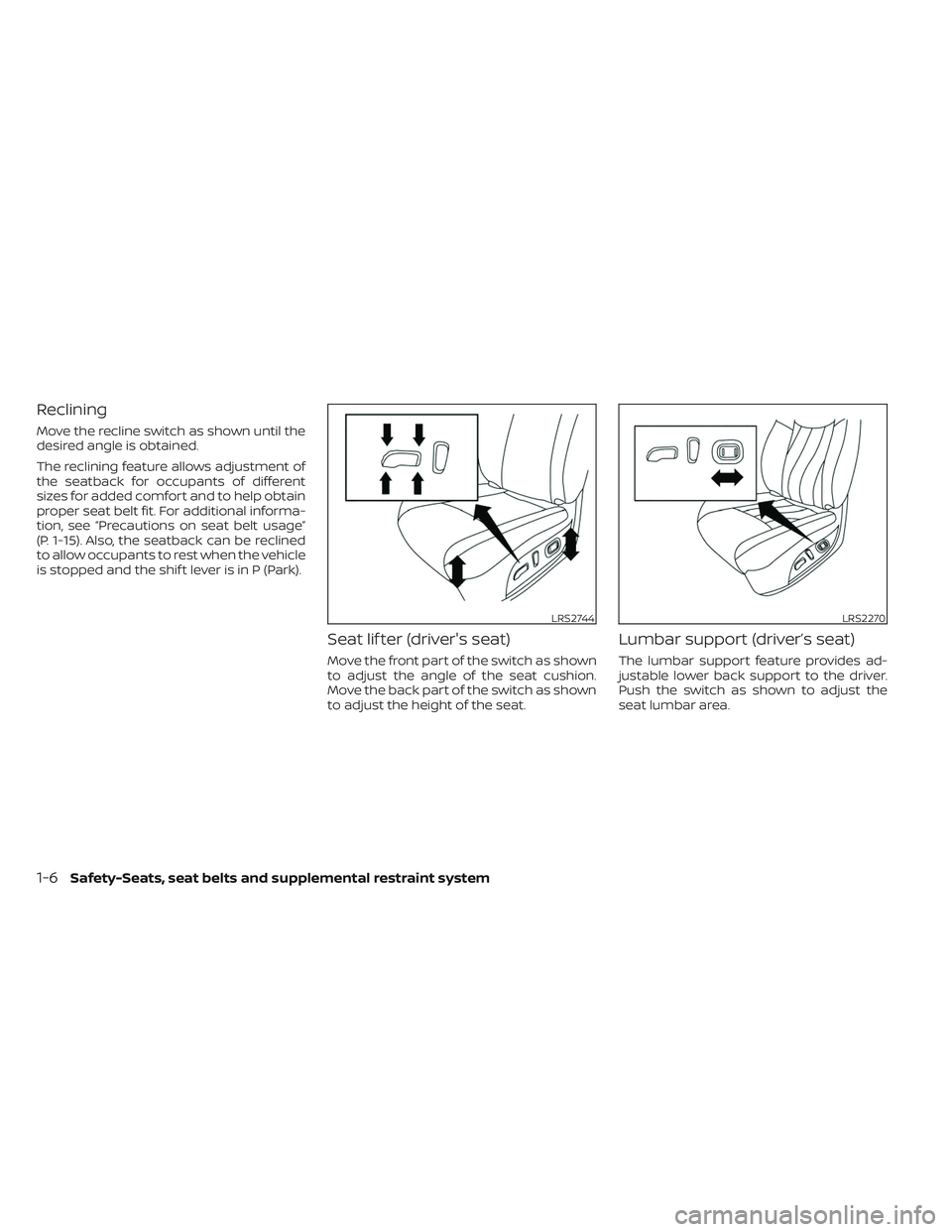
Move the recline switch as shown until the
desired angle is obtained.
The reclining feature allows adjustment of
the seatback for occupants of different
sizes for added comfort and to help obtain
proper seat belt fit. For additional informa-
tion, see “Precautions on seat belt usage”
(P. 1-15). Also, the seatback can be reclined
to allow occupants to rest when the vehicle
is stopped and the shif t lever is in P (Park).
Seat lif ter (driver's seat)
Move the front part of the switch as shown
to adjust the angle of the seat cushion.
Move the back part of the switch as shown
to adjust the height of the seat.
Lumbar support (driver’s seat)
The lumbar support feature provides ad-
justable lower back support to the driver.
Push the switch as shown to adjust the
seat lumbar area.
LRS2744LRS2270
1-6Safety-Seats, seat belts and supplemental restraint system
Page 42 of 644
Center of rear seat
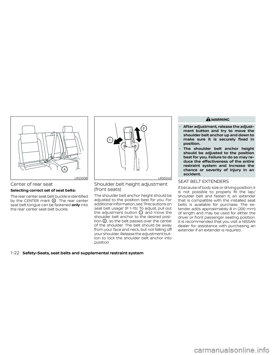
Selecting correct set of seat belts:
The rear center seat belt buckle is identified
by the CENTER mark
OA. The rear center
seat belt tongue can be fastened onlyinto
the rear center seat belt buckle.
Shoulder belt height adjustment
(front seats)
The shoulder belt anchor height should be
adjusted to the position best for you. For
additional information, see “Precautions on
seat belt usage” (P. 1-15). To adjust, pull out
the adjustment button
O1and move the
shoulder belt anchor to the desired posi-
tion
O2, so the belt passes over the center
of the shoulder. The belt should be away
from your face and neck, but not falling off
your shoulder. Release the adjustment but-
ton to lock the shoulder belt anchor into
position.
WARNING
• Af ter adjustment, release the adjust-
ment button and try to move the
shoulder belt anchor up and down to
make sure it is securely fixed in
position.
• The shoulder belt anchor height
should be adjusted to the position
best for you. Failure to do so may re-
duce the effectiveness of the entire
restraint system and increase the
chance or severity of injury in an
accident.
SEAT BELT EXTENDERS
If, because of body size or driving position, it
is not possible to properly fit the lap/
shoulder belt and fasten it, an extender
that is compatible with the installed seat
belts is available for purchase. The ex-
tender adds approximately 8 in (200 mm)
of length and may be used for either the
driver or front passenger seating position.
It is recommended that you visit a NISSAN
dealer for assistance with purchasing an
extender if an extender is required.
LRS3308LRS0242
1-22Safety-Seats, seat belts and supplemental restraint system
Page 207 of 644
3 Pre-driving checks and adjustments
Keys.............................................3-2NISSAN Intelligent Key® .......................3-2
NISSAN Vehicle Immobilizer System
keys..........................................3-4
Doors ...........................................3-4
Locking with key .............................3-5
Locking with inside lock knob ................3-6
Locking with power door lock switch .........3-6
Rear doors (King Cab® models) ............... 3-7
Automatic door locks ........................3-8
Child safety rear door lock
(if so equipped) ...............................3-9
NISSAN Intelligent Key® system ..................3-9
Operating range ............................. 3-11
Door locks/unlocks precaution ...............3-11
NISSAN Intelligent Key® Operation ...........3-12
How to use the remote keyless entry
function ..................................... 3-16
Warning signals ............................. 3-19
Troubleshooting guide ......................3-20
Remote Engine Start (if so equipped) ...........3-22
Remote Engine Start operating range .......3-22
Remote starting the vehicle .................3-23
Extending engine run time ..................3-23
Canceling a Remote Engine Start ...........3-23 Conditions the Remote Engine Start will
notwork ....................................
3-24
Hood ........................................... 3-25
Fuel-filler door .................................. 3-25
Gasoline fuel engines .......................3-26
Steering wheel ................................. 3-28
Manual operation (if so equipped) ...........3-28
Automatic operation (if so equipped) ........3-29
Sun visors ...................................... 3-30
Vanity mirrors (if so equipped) ...............3-30
Card holder (driver’s side only) ...............3-31
Mirrors ......................................... 3-31
Manual anti-glare rearview mirror
(if so equipped) .............................. 3-31
Automatic anti-glare rearview mirror
(if so equipped) .............................. 3-31
Outside mirrors ............................. 3-33
Truck box ...................................... 3-37
Tailgate ..................................... 3-37
Tie down hooks ............................. 3-41
Memor
y Seat (if so equipped) ..................3-41
Memory storage function ...................3-42
Entry/exit function .......................... 3-43
System operation ........................... 3-43
Page 226 of 644
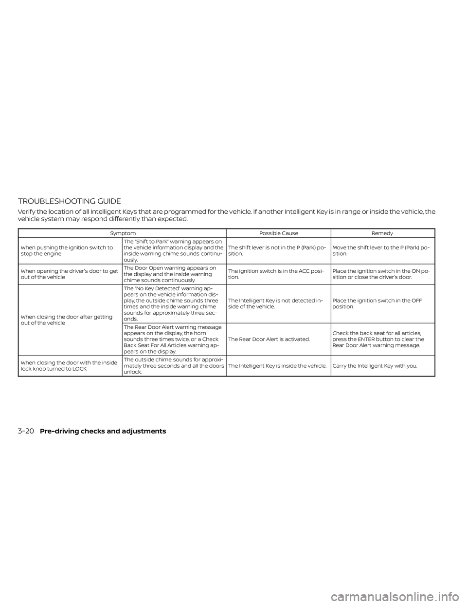
TROUBLESHOOTING GUIDE
Verif y the location of all Intelligent Keys that are programmed for the vehicle. If another Intelligent Key is in range or inside the vehicle, the
vehicle system may respond differently than expected.
SymptomPossible CauseRemedy
When pushing the ignition switch to
stop the engine The “Shif t to Park” warning appears on
the vehicle information display and the
inside warning chime sounds continu-
ously. The shif t lever is not in the P (Park) po-
sition.
Move the shif t lever to the P (Park) po-
sition.
When opening the driver's door to get
out of the vehicle The Door Open warning appears on
the display and the inside warning
chime sounds continuously. The ignition switch is in the ACC posi-
tion.
Place the ignition switch in the ON po-
sition or close the driver’s door.
When closing the door af ter getting
out of the vehicle The “No Key Detected” warning ap-
pears on the vehicle information dis-
play, the outside chime sounds three
times and the inside warning chime
sounds for approximately three sec-
onds.
The Intelligent Key is not detected in-
side of the vehicle.
Place the ignition switch in the OFF
position.
The Rear Door Alert warning message
appears on the display, the horn
sounds three times twice, or a Check
Back Seat For All Articles warning ap-
pears on the display. The Rear Door Alert is activated.
Check the back seat for all articles,
press the ENTER button to clear the
Rear Door Alert warning message.
When closing the door with the inside
lock knob turned to LOCK The outside chime sounds for approxi-
mately three seconds and all the doors
unlock.
The Intelligent Key is inside the vehicle. Carry the Intelligent Key with you.
3-20Pre-driving checks and adjustments
Page 234 of 644
Loose Fuel Cap warning
The Loose Fuel Cap warning appears in the
vehicle information display when the fuel-
filler cap is not tightened correctly af ter the
vehicle has been refueled. It may take a few
driving trips for the message to be dis-
played. To turn off the warning, perform the
following:
1. Remove and install the fuel-filler cap aspreviously described as soon as
possible.
2. Tighten the fuel-filler cap until a single click is heard.
WARNING
• Do not adjust the steering wheel
while driving. You could lose control
of your vehicle and cause an
accident.
• Do not adjust the steering wheel any
closer to you than is necessary for
proper steering operation and com-
fort. The driver's air bag inflates with
great force. If you are unrestrained,
leaning forward, sitting sideways or
out of position in any way, you are at
greater risk of injury or death in a
crash. You may also receive serious
or fatal injuries from the air bag if you
are up against it when it inflates. Al-
ways sit back against the seatback
and as far away as practical from the
steering wheel. Always use the seat
belts.
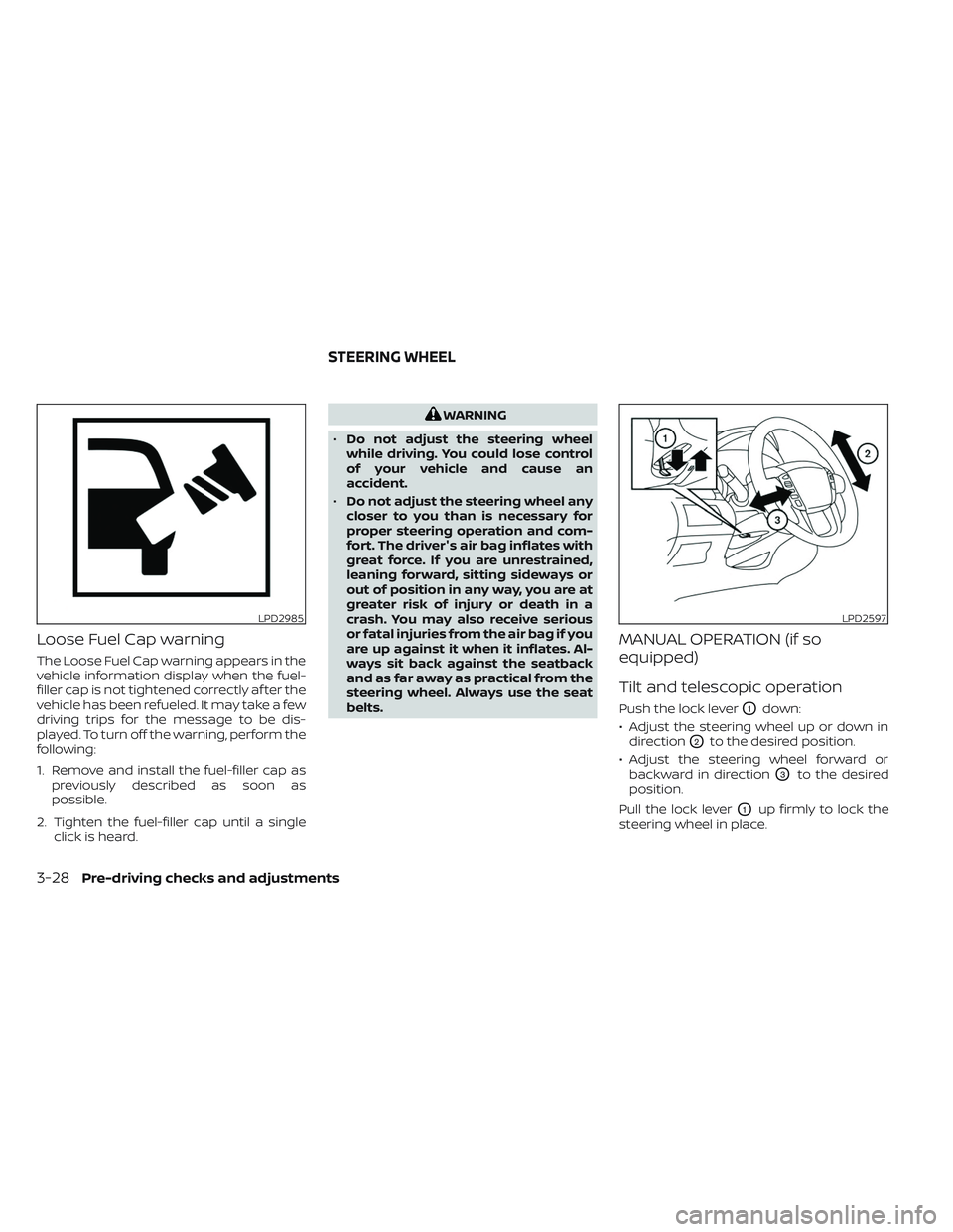
MANUAL OPERATION (if so
equipped)
Tilt and telescopic operation
Push the lock leverO1down:
• Adjust the steering wheel up or down in direction
O2to the desired position.
• Adjust the steering wheel forward or backward in direction
O3to the desired
position.
Pull the lock lever
O1up firmly to lock the
steering wheel in place.
LPD2985LPD2597
STEERING WHEEL
3-28Pre-driving checks and adjustments
Page 235 of 644
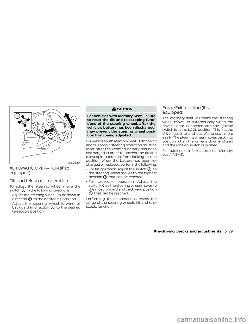
AUTOMATIC OPERATION (if so
equipped)
Tilt and telescopic operation
To adjust the steering wheel move the
switch
O1in the following directions:
• Adjust the steering wheel up or down in direction
O2to the desired tilt position.
• Adjust the steering wheel forward or backward in direction
O3to the desired
telescopic position.
CAUTION
For vehicles with Memory Seat: Failure
to reset the tilt and telescoping func-
tions of the steering wheel, af ter the
vehicle’s battery has been discharged,
may prevent the steering wheel posi-
tion from being adjusted.
For vehicles with Memory Seat: Both the tilt
and telescopic steering operation must be
reset af ter the vehicle’s battery has been
discharged in order to prevent the tilt and
telescopic operation from locking in one
position. When the battery has been re-
charged or replaced, perform the following:
• For tilt operation: Adjust the switch
O1so
the steering wheel moves to the highest
position
O2that can be reached.
• For telescopic operation: Adjust the switch
O1so the steering wheel moves to
the most forward and backward position
O3that can be reached.
Performing these operations resets the
range of the steering wheel’s tilt and tele-
scopic function.
Entry/Exit function (if so
equipped)
The memory seat will make the steering
wheel move up automatically when the
driver's door is opened and the ignition
switch is in the LOCK position. This lets the
driver get into and out of the seat more
easily. The steering wheel moves back into
position when the driver's door is closed
and the ignition switch is pushed.
For additional information, see “Memory
seat” (P. 3-41).
LPD2580
Pre-driving checks and adjustments3-29
Page 248 of 644
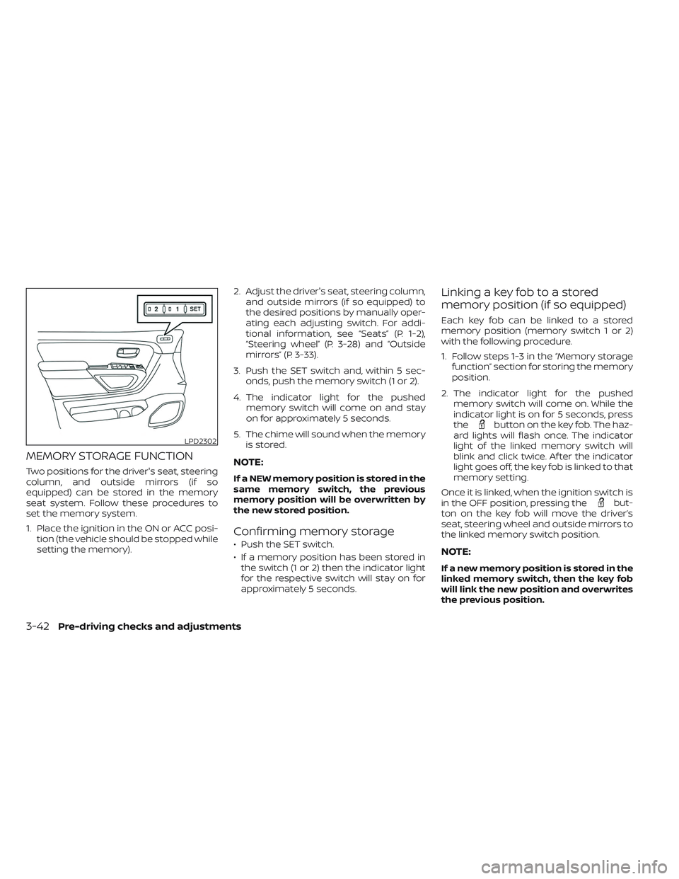
MEMORY STORAGE FUNCTION
Two positions for the driver's seat, steering
column, and outside mirrors (if so
equipped) can be stored in the memory
seat system. Follow these procedures to
set the memory system.
1. Place the ignition in the ON or ACC posi-tion (the vehicle should be stopped while
setting the memory). 2. Adjust the driver's seat, steering column,
and outside mirrors (if so equipped) to
the desired positions by manually oper-
ating each adjusting switch. For addi-
tional information, see “Seats” (P. 1-2),
“Steering wheel” (P. 3-28) and “Outside
mirrors” (P. 3-33).
3. Push the SET switch and, within 5 sec- onds, push the memory switch (1 or 2).
4. The indicator light for the pushed memory switch will come on and stay
on for approximately 5 seconds.
5. The chime will sound when the memory is stored.NOTE:
If a NEW memory position is stored in the
same memory switch, the previous
memory position will be overwritten by
the new stored position.
Confirming memory storage
• Push the SET switch.
• If a memory position has been stored inthe switch (1 or 2) then the indicator light
for the respective switch will stay on for
approximately 5 seconds.
Linking a key fob to a stored
memory position (if so equipped)
Each key fob can be linked to a stored
memory position (memory switch 1 or 2)
with the following procedure.
1. Follow steps 1-3 in the “Memory storage function” section for storing the memory
position.
2. The indicator light for the pushed memory switch will come on. While the
indicator light is on for 5 seconds, press
the
button on the key fob. The haz-
ard lights will flash once. The indicator
light of the linked memory switch will
blink and click twice. Af ter the indicator
light goes off, the key fob is linked to that
memory setting.
Once it is linked, when the ignition switch is
in the OFF position, pressing the
but-
ton on the key fob will move the driver’s
seat, steering wheel and outside mirrors to
the linked memory switch position.
NOTE:
If a new memory position is stored in the
linked memory switch, then the key fob
will link the new position and overwrites
the previous position.
LPD2302
3-42Pre-driving checks and adjustments
Page 249 of 644
ENTRY/EXIT FUNCTION
This system is designed so that the driver's
seat and steering column will automati-
cally move when the shif t lever is in the P
(Park) position. This allows the driver to
easily get in and out of the driver’s seat.
The driver’s seat will slide backward and
the steering column will move up:
• When the driver’s door is opened with theignition switch in the OFF position.
• When the ignition switch is changed from ACC to OFF with the driver’s door open.
The driver’s seat and steering wheel will
return to the previous position:
• When the ignition switch is changed from ACC or ON while the shif t lever is in the P
(Park) position.
The entry/exit function can be adjusted or
canceled through the vehicle settings in
the vehicle information display by perform-
ing the following:
• Switch the Exit Seat Slide from ON to OFF.
• Switch the Exit Steering UP from ON to OFF.
Restarting the entry/exit function
If the battery cable is disconnected, or if the
fuse opens, the stored memory positions
will be lost and some of the functions will
be restricted:
1. Drive the vehicle over 25 mph (40 km/h).
OR
2. Open and close the driver's door more than two times with the ignition switch
in the OFF position.
The entry/exit function should now work
properly.
SYSTEM OPERATION
The memory seat system will not work or
will stop operating under the following
conditions:
• When the vehicle speed is above 4 mph (7 km/h).
• When any of the memory switches are pushed while the memory seat system is
operating. • When the switch for the driver’s seat and
steering column is pushed while the
memory seat system is operating.
• When the seat has already been moved to the memorized position.
• When no seat position is stored in the memory switch.
• When the shif t lever is moved from P (Park) to any other position.
The memory seat system can be adjusted
and canceled. It is recommended you visit
a NISSAN dealer for this service.
Pre-driving checks and adjustments3-43
Page 293 of 644
WARNING
• It is unlawful in most jurisdictions for
a person to drive a motor vehicle
which is equipped with a television
monitor or screen that is visible, di-
rectly or indirectly, to the driver while
operating the vehicle. In the interest
of safety, the unit should never be
installed where it will be directly or
indirectly visible, by the operator of
the motor vehicle.
• For safety reasons when changing
discs, it is recommended that the ve-
hicle is not in motion, and that you do
not allow children to unfasten safety
belts to change discs or make any
adjustments to the system. System
adjustments can be accomplished
using the remote control, while
safety belts remain fastened. •
Enjoy your RSI system but remember
that safety of all passengers remains
the number one priority. Devices in-
stalled in the USB, HDMI, or head-
phone jack may protrude and create
a potential eye impact hazard for un-
belted passengers during a vehicle
accident. To reduce the risk of injury,
use only SD cards (hidden on lef t side
of driver side monitor) or low-profile
USB storage devices.
CAUTION
• If your vehicle is equipped with a
wireless rear seat audio system or
any other wireless infrared device,
make sure it is powered off when op-
erating the RSI system. If both sys-
tems are powered on at the same
time, the two systems may obstruct
each other, possibly creating unde-
sirable audio interference through
the wireless headphones.
• Do not touch the inner pins of the
jacks on the front panel. Electrostatic
discharge may cause permanent
damage to the device. •
The LCD display screen is not touch-
screen. Do not put pressure or add
suction cups on the screen.
• Caution children to avoid touching or
scratching the screen, as it may be-
come dirty or damaged.
• Be sure to run the vehicle engine
while using the system. Using this
system without running the engine
can result in battery drain. To avoid
the risk of battery drain, please re-
member to turn off the system when
the vehicle is not in use.
REAR SEAT INFOTAINMENT (RSI) (if
so equipped)
Monitor, climate, audio, phone and voice recognition systems4-43