engine coolant NISSAN TITAN 2023 Owners Manual
[x] Cancel search | Manufacturer: NISSAN, Model Year: 2023, Model line: TITAN, Model: NISSAN TITAN 2023Pages: 644, PDF Size: 7.8 MB
Page 16 of 644
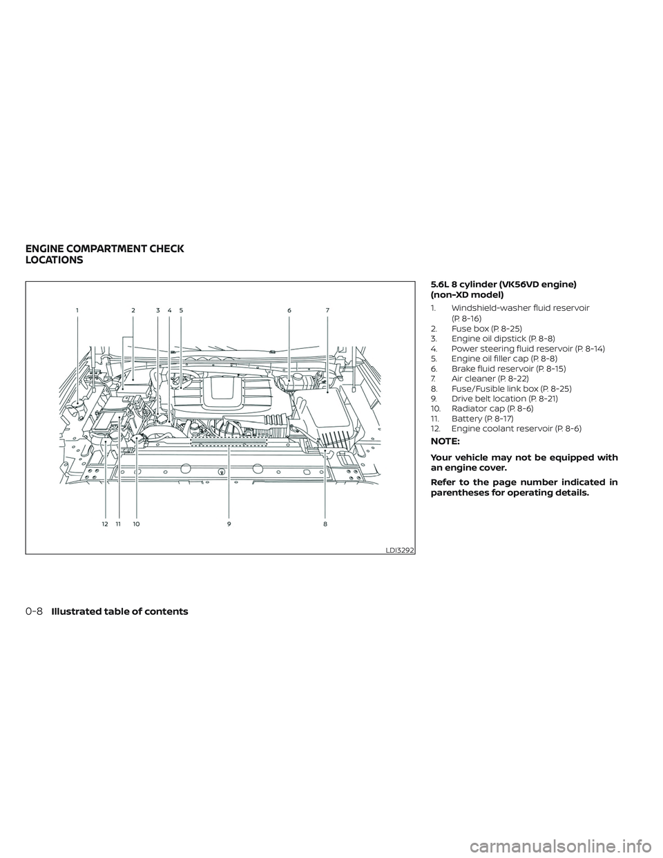
5.6L 8 cylinder (VK56VD engine)
(non-XD model)
1. Windshield-washer fluid reservoir(P. 8-16)
2. Fuse box (P. 8-25)
3. Engine oil dipstick (P. 8-8)
4. Power steering fluid reservoir (P. 8-14)
5. Engine oil filler cap (P. 8-8)
6. Brake fluid reservoir (P. 8-15)
7. Air cleaner (P. 8-22)
8. Fuse/Fusible link box (P. 8-25)
9. Drive belt location (P. 8-21)
10. Radiator cap (P. 8-6)
11. Battery (P. 8-17)
12. Engine coolant reservoir (P. 8-6)
NOTE:
Your vehicle may not be equipped with
an engine cover.
Refer to the page number indicated in
parentheses for operating details.
LDI3292
ENGINE COMPARTMENT CHECK
LOCATIONS
0-8Illustrated table of contents
Page 17 of 644
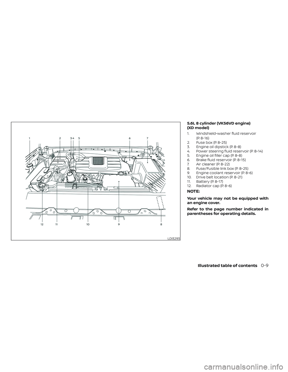
5.6L 8 cylinder (VK56VD engine)
(XD model)
1. Windshield-washer fluid reservoir(P. 8-16)
2. Fuse box (P. 8-25)
3. Engine oil dipstick (P. 8-8)
4. Power steering fluid reservoir (P. 8-14)
5. Engine oil filler cap (P. 8-8)
6. Brake fluid reservoir (P. 8-15)
7. Air cleaner (P. 8-22)
8. Fuse/Fusible link box (P. 8-25)
9. Engine coolant reservoir (P. 8-6)
10. Drive belt location (P. 8-21)
11. Battery (P. 8-17)
12. Radiator cap (P. 8-6)
NOTE:
Your vehicle may not be equipped with
an engine cover.
Refer to the page number indicated in
parentheses for operating details.
LDI3293
Illustrated table of contents0-9
Page 105 of 644
2 Instruments and controls
Instrument panel................................2-4
Meters and gauges .............................2-6
Speedometer and odometer .................2-6
Tachometer ..................................2-8
Engine coolant temperature gauge ..........2-8
Fuel gauge ...................................2-9
Distance To Empty (DTE) .....................2-9
Auxiliary gauges (if so equipped) ............2-10
Off-road and 4–Wheel Drive (4WD)
monitor (if so equipped) ......................2-11
Eco Drive Report (if so equipped) ............2-12
Warning lights, indicator lights and audible
reminders ...................................... 2-13
Checking lights .............................. 2-15
Warning/Indicator lights (red) ...............2-15
Warning/Indicator lights (yellow) ............2-19
Warning/Indicator lights (other) .............2-23
Audible reminders ........................... 2-24
Vehicle information display .....................2-24
How to use the vehicle information
display ...................................... 2-25
Startup display .............................. 2-25
Settings ..................................... 2-25
Vehicle information display warnings
and indicators ............................... 2-33
Security systems ............................... 2-40Vehicle security system
.....................2-40
NISSAN Vehicle Immobilizer System .........2-41
Wiper and washer switch .......................2-42
Switch operation ............................ 2-42
Rain-sensing auto wiper system
(if so equipped) .............................. 2-44
Rear window and/or outside mirror defroster
switch (if so equipped) ......................... 2-45
Headlight switch ............................... 2-45
Headlight control switch ....................2-45
LED Daytime Running Lights (DRL)
system (if so equipped) ......................2-51
Instrument brightness control ..............2-51
Turn signal switch ........................... 2-52
Fog light switch (if so equipped) ................2-52
Horn ........................................... 2-53
Cargo lamp switch ............................. 2-53
Climate
controlled seat switches
(if so equipped) ................................. 2-54
Heated seat switches (if so equipped) ..........2-55
Heated rear seat switches (if so equipped) .....2-56
Heated steering wheel switch (if so equipped) . . 2-57
Warning systems switch .......................2-58
Vehicle Dynamic Control (VDC) OFF switch .....2-59
Hill descent control switch (if so equipped) .....2-59
Page 110 of 644
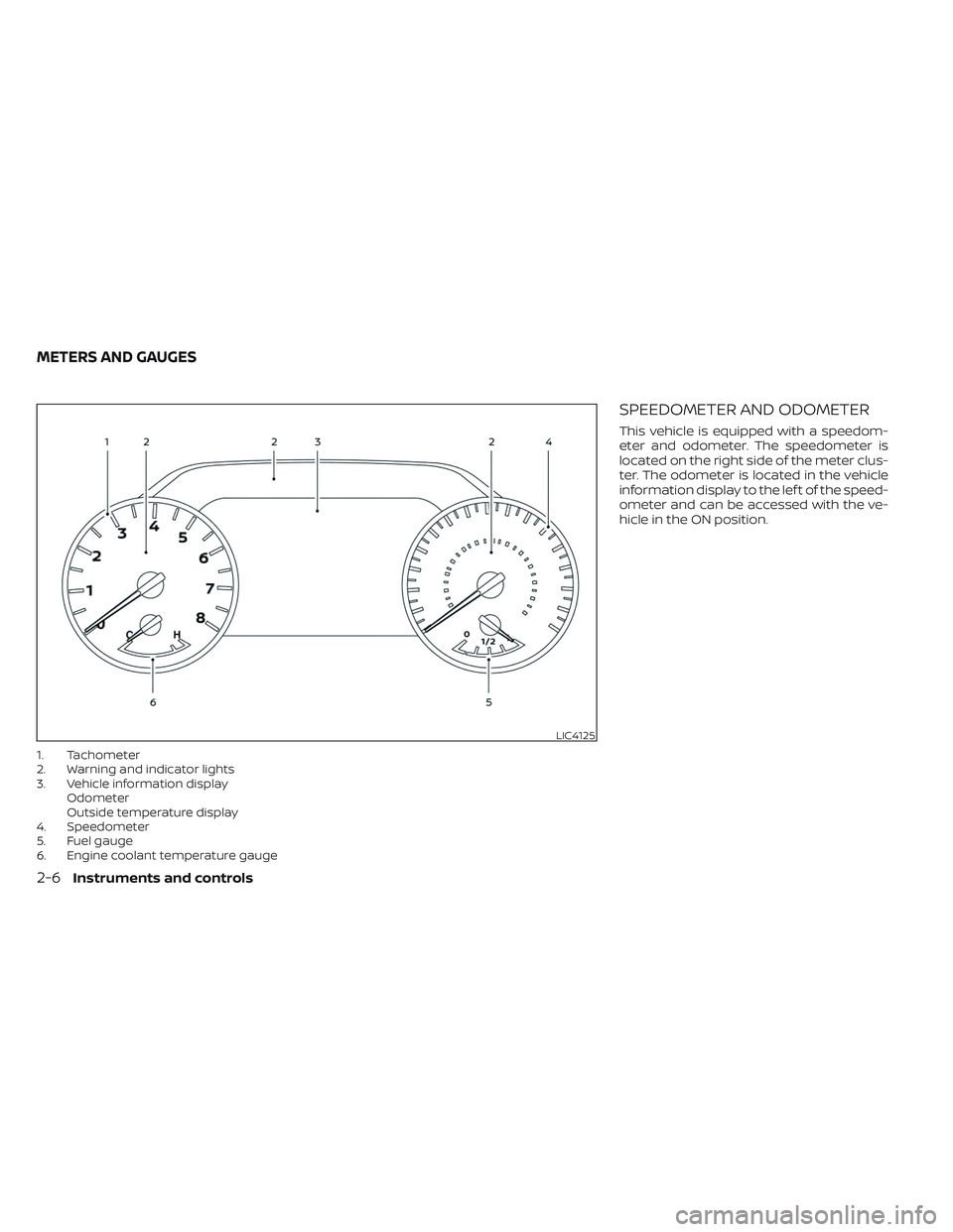
1. Tachometer
2. Warning and indicator lights
3. Vehicle information displayOdometer
Outside temperature display
4. Speedometer
5. Fuel gauge
6. Engine coolant temperature gauge
SPEEDOMETER AND ODOMETER
This vehicle is equipped with a speedom-
eter and odometer. The speedometer is
located on the right side of the meter clus-
ter. The odometer is located in the vehicle
information display to the lef t of the speed-
ometer and can be accessed with the ve-
hicle in the ON position.
LIC4125
METERS AND GAUGES
2-6Instruments and controls
Page 112 of 644
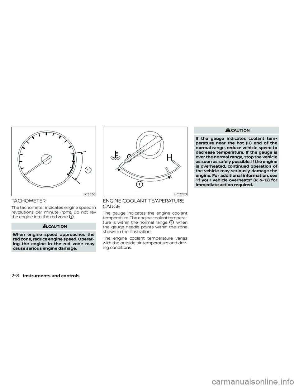
TACHOMETER
The tachometer indicates engine speed in
revolutions per minute (rpm). Do not rev
the engine into the red zone
O1.
CAUTION
When engine speed approaches the
red zone, reduce engine speed. Operat-
ing the engine in the red zone may
cause serious engine damage.
ENGINE COOLANT TEMPERATURE
GAUGE
The gauge indicates the engine coolant
temperature. The engine coolant tempera-
ture is within the normal range
O1when
the gauge needle points within the zone
shown in the illustration.
The engine coolant temperature varies
with the outside air temperature and driv-
ing conditions.
CAUTION
If the gauge indicates coolant tem-
perature near the hot (H) end of the
normal range, reduce vehicle speed to
decrease temperature. If the gauge is
over the normal range, stop the vehicle
as soon as safely possible. If the engine
is overheated, continued operation of
the vehicle may seriously damage the
engine. For additional information, see
“If your vehicle overheats” (P. 6-12) for
immediate action required.
LIC3536LIC2220
2-8Instruments and controls
Page 135 of 644
Maintenance
The maintenance menu allows the user to set reminders for various vehicle maintenance items.
Some menu items shown below may not be equipped on your vehicle.
WARNING
The tire replacement indicator is not a substitute for regular tire checks, including tire pressure checks. For additional informa-
tion, see “Changing wheels and tires” (P. 8-44). Many factors including tire inflation, alignment, driving habits and road conditions
affect tire wear and when tires should be replaced. Setting the tire replacement indicator for a certain driving distance does not
mean your tires will last that long. Use the tire replacement indicator as a guide only and always perform regular tire checks.
Failure to perform regular tire checks, including tire pressure checks could result in tire failure. Serious vehicle damage could
occur and may lead to a collision, which could result in serious personal injury or death.
Menu item Explanation
Maintenance Allows user to cycle through various maintenance items and set reminders to perform maintenance at spe-
cific intervals.
Oil and Filter Allows user to set an oil and filter reminder at a specific interval or reset the current one.
Air Filter Allows user to set an air filter reminder at a specific interval or reset the current one.
Tire Allows user to set a tire reminder at a specific interval or reset the current one.
Brake Pad Allows user to set a brake pad reminder at a specific interval or reset the current one.
Brake Fluid Allows user to set a brake fluid reminder at a specific interval or reset the current one.
Battery Allows user to set a battery reminder at a specific interval or reset the current one.
Transmission Fluid Allows user to set a transmission fluid reminder at a specific interval or reset the current one.
Engine Coolant Allows user to set an engine coolant reminder at a specific interval or reset the current one.
Spark Plug Allows user to set a spark plug reminder at a specific interval or reset the current one.
Other Allows user to set a reminder, other than for the maintenance items listed above, at a specific interval or re-
set the current one.
Instruments and controls2-31
Page 283 of 644
Operating tips
• Keep the windows closed while the airconditioner is in operation.
• Af ter parking in the sun, drive for 2 or 3 minutes with the windows open to vent
hot air from the passenger compart-
ment. Then, close the windows. This al-
lows the air conditioner to cool the inte-
rior more quickly.
• The air conditioning system should be
operated for approximately 10 minutes
at least once a month. This helps pre-
vent damage to the system due to lack
of lubrication.
• A visible mist may be seen coming from the ventilators in hot, humid conditions
as the air is cooled rapidly. This does not
indicate a malfunction.
• If the engine coolant temperature
gauge indicates engine coolant tem-
perature over the normal range, turn
the air conditioner off. For additional
information, see “If your vehicle over-
heats” (P. 6-12).
AIR FLOW CHARTS
The following charts show the button and
dial positions for MAXIMUM AND QUICK
heating, cooling or defrosting. For addi-
tional information on heating and cooling,
see “Heater and air conditioner (manual)”
(P. 4-28). The air recirculation (
) but-
ton should always be in the OFF position
for heating and defrosting.
Monitor, climate, audio, phone and voice recognition systems4-33
Page 291 of 644
To turn system off
Press the ON-OFF button.
Rear window and/or outside
mirror defroster switch (if so
equipped)
For additional information, see “Rear win-
dow and/or outside mirror defroster
switch” (P. 2-45).
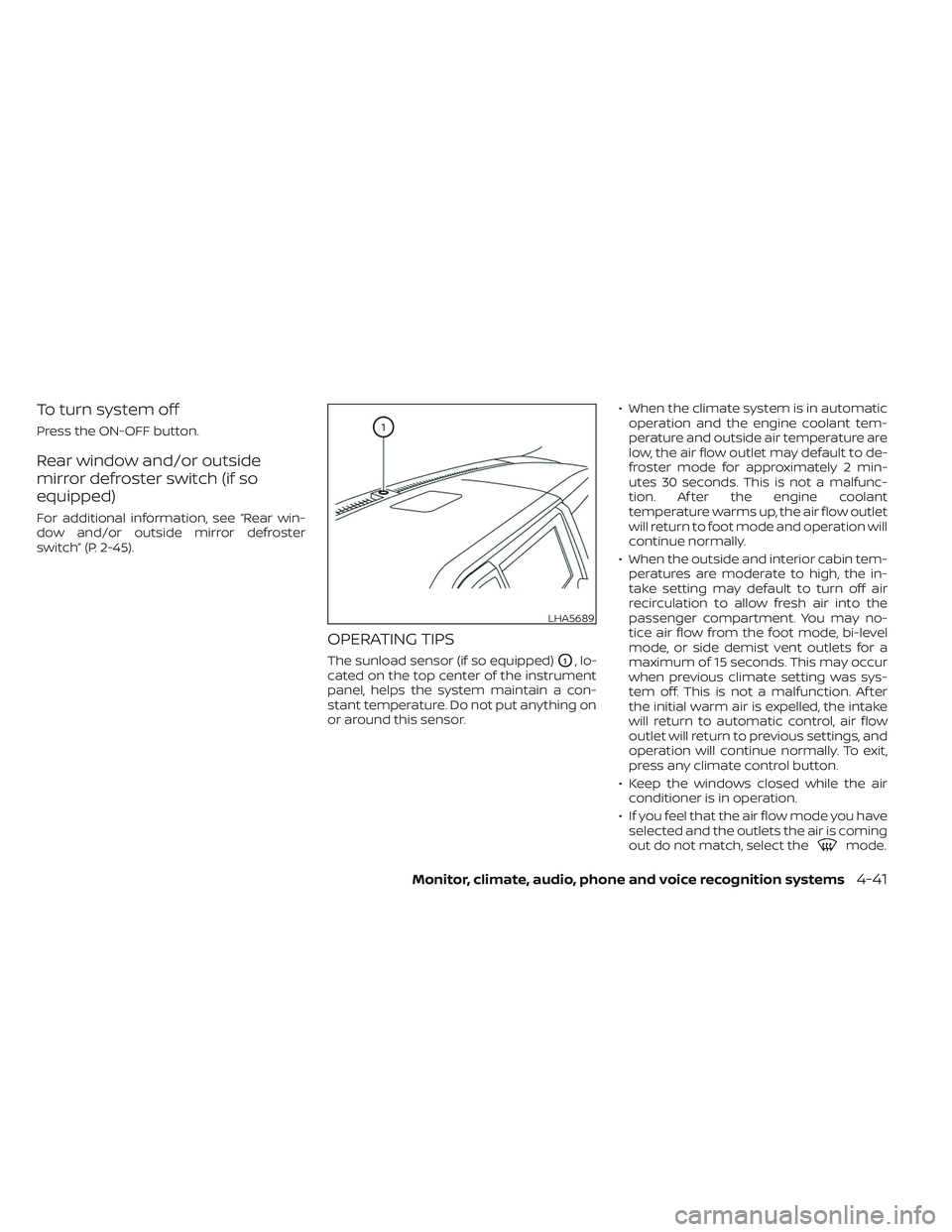
OPERATING TIPS
The sunload sensor (if so equipped)O1, lo-
cated on the top center of the instrument
panel, helps the system maintain a con-
stant temperature. Do not put anything on
or around this sensor. • When the climate system is in automatic
operation and the engine coolant tem-
perature and outside air temperature are
low, the air flow outlet may default to de-
froster mode for approximately 2 min-
utes 30 seconds. This is not a malfunc-
tion. Af ter the engine coolant
temperature warms up, the air flow outlet
will return to foot mode and operation will
continue normally.
• When the outside and interior cabin tem- peratures are moderate to high, the in-
take setting may default to turn off air
recirculation to allow fresh air into the
passenger compartment. You may no-
tice air flow from the foot mode, bi-level
mode, or side demist vent outlets for a
maximum of 15 seconds. This may occur
when previous climate setting was sys-
tem off. This is not a malfunction. Af ter
the initial warm air is expelled, the intake
will return to automatic control, air flow
outlet will return to previous settings, and
operation will continue normally. To exit,
press any climate control button.
• Keep the windows closed while the air conditioner is in operation.
• If you feel that the air flow mode you have selected and the outlets the air is coming
out do not match, select the
mode.
LHA5689
Monitor, climate, audio, phone and voice recognition systems4-41
Page 337 of 644
Intelligent Driver Alertness (I-DA)
system limitations......................... 5-102
Break-in schedule ............................. 5-103
Fuel efficient driving tips .......................5-104
Increasing fuel economy ......................5-105
Using 4–Wheel Drive (4WD) (if so equipped) ....5-105
Transfer case shif ting procedures ..........5-106
Electronic locking rear differential (E-Lock)
system (if so equipped) ......................... 5-111
Parking/parking on hills .......................5-112
Power steering ................................ 5-113
Brake system ................................. 5-114
Brake precautions .......................... 5-114
Anti-lock Braking System (ABS) .............5-114
Brake Assist ................................ 5-115
Active Brake Limited Slip (ABLS) system .......5-116
Vehicle Dynamic Control (VDC) system .........5-117
Brake force distribution ....................5-118Hill descent control system (if so equipped) . . . 5-119
Hill start assist system
........................5-120
Front and rear sonar system (if so equipped) . . 5-121 System operation .......................... 5-122
How to enable/disable the sonar
system ..................................... 5-124
Sonar limitations ........................... 5-125
System maintenance ......................5-126
Cold weather driving .......................... 5-126
Freeing a frozen door lock ..................5-126
Antifreeze .................................. 5-126
Battery..................................... 5-126
Draining of coolant water ..................5-126
Tire equipment ............................. 5-127
Special winter equipment ..................5-127
Driving on snow or ice ......................5-127
Engine block heater (if so equipped) ........5-128
Page 352 of 644
ENGINE PROTECTION MODE
The engine has an engine protection mode
to reduce the chance of damage if the
coolant temperature becomes too high
(for example, when climbing steep grades
in high temperatures with heavy loads,
such as when towing a trailer). When the
engine temperature reaches a certain
level:
• The engine coolant temperature gaugewill move toward the H position.
• Engine power may be reduced.
• The air conditioning cooling function may be automatically turned off for a short
time (the blower will continue to operate).
Engine power and, under some conditions,
vehicle speed will decrease. Vehicle speed
can be controlled with the accelerator
pedal, but the vehicle may not accelerate at
the desired speed. The transmission will
downshif t or upshif t as it reaches pre-
scribed shif t points. You can also shif t
manually.
As driving conditions change and engine
coolant temperature is reduced, vehicle
speed can be increased using the accel-
erator pedal, and the air conditioning cool-
ing function will automatically be turned
back on. The Malfunction Indicator Light (MIL) may
also come on if the engine coolant tem-
perature is not reduced or the air condi-
tioning cooling function does not turn back
on. If
only it remains on, you do not need to
have your vehicle towed, but have it in-
spected soon. It is recommended that you
visit a NISSAN dealer for this service. For
additional information, see “Malfunction In-
dicator Light (MIL)” (P. 2-22).
WARNING
Overheating can result in reduced en-
gine power and vehicle speed. The re-
duced speed may be lower than other
traffic, which could increase the chance
of a collision. Be especially careful
when driving. If the vehicle cannot
maintain a safe driving speed, pull to
the side of the road in a safe area. Allow
the engine to cool and return to normal
operation. For additional information,
see “If your vehicle overheats” (P. 6-12).
CAUTION
Running the engine with the engine oil
pressure warning light on could cause
serious damage to the engine almost
immediately. Such damage is not cov-
ered by warranty. Turn off the engine as
soon as it is safe to do so.
AUTOMATIC TRANSMISSION (A/T)
WARNING
• Do not depress the accelerator pedal
while shif ting from P (Park) or N (Neu-
tral) to R (Reverse) or D (Drive). Always
depress the brake pedal until shif ting
is completed. Failure to do so could
cause you to lose control and have an
accident.
• Cold engine idle speed is high, so use
caution when shif ting into a forward
or reverse gear before the engine has
warmed up.
• Never shif t to either the P (Park) or R
(Reverse) position while the vehicle is
moving forward and P (Park) or D
(Drive) position while the vehicle is
reversing. This could cause an acci-
dent or damage the transmission.
DRIVING THE VEHICLE
5-18Starting and driving