instrument cluster NISSAN VERSA 2006 Workshop Service User Guide
[x] Cancel search | Manufacturer: NISSAN, Model Year: 2006, Model line: VERSA, Model: NISSAN VERSA 2006Pages: 2896, PDF Size: 64.73 MB
Page 2118 of 2896
IP-18
INSTRUMENT PANEL ASSEMBLY
Revision: June 20062007 Versa
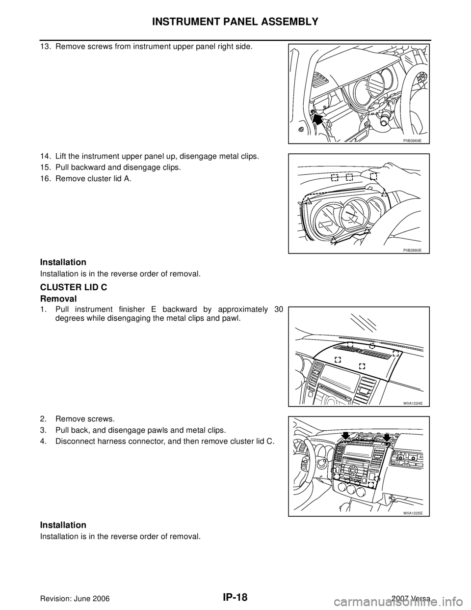
13. Remove screws from instrument upper panel right side.
14. Lift the instrument upper panel up, disengage metal clips.
15. Pull backward and disengage clips.
16. Remove cluster lid A.
Installation
Installation is in the reverse order of removal.
CLUSTER LID C
Removal
1. Pull instrument finisher E backward by approximately 30
degrees while disengaging the metal clips and pawl.
2. Remove screws.
3. Pull back, and disengage pawls and metal clips.
4. Disconnect harness connector, and then remove cluster lid C.
Installation
Installation is in the reverse order of removal.
PIIB3969E
PIIB2880E
WIIA1224E
WIIA1225E
Page 2120 of 2896
IP-20
INSTRUMENT PANEL ASSEMBLY
Revision: June 20062007 Versa
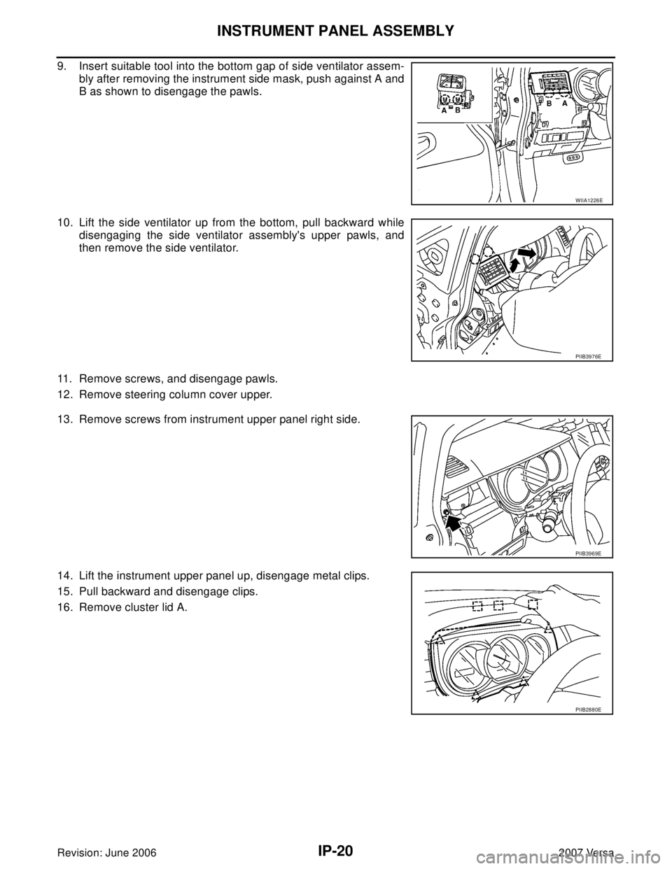
9. Insert suitable tool into the bottom gap of side ventilator assem-
bly after removing the instrument side mask, push against A and
B as shown to disengage the pawls.
10. Lift the side ventilator up from the bottom, pull backward while
disengaging the side ventilator assembly's upper pawls, and
then remove the side ventilator.
11. Remove screws, and disengage pawls.
12. Remove steering column cover upper.
13. Remove screws from instrument upper panel right side.
14. Lift the instrument upper panel up, disengage metal clips.
15. Pull backward and disengage clips.
16. Remove cluster lid A.
WIIA1226E
PIIB3976E
PIIB3969E
PIIB2880E
Page 2274 of 2896
LT-66
HAZARD SWITCH
Revision: June 20062007 Versa
HAZARD SWITCHPFP:25290
Removal and InstallationEKS00HYI
REMOVAL
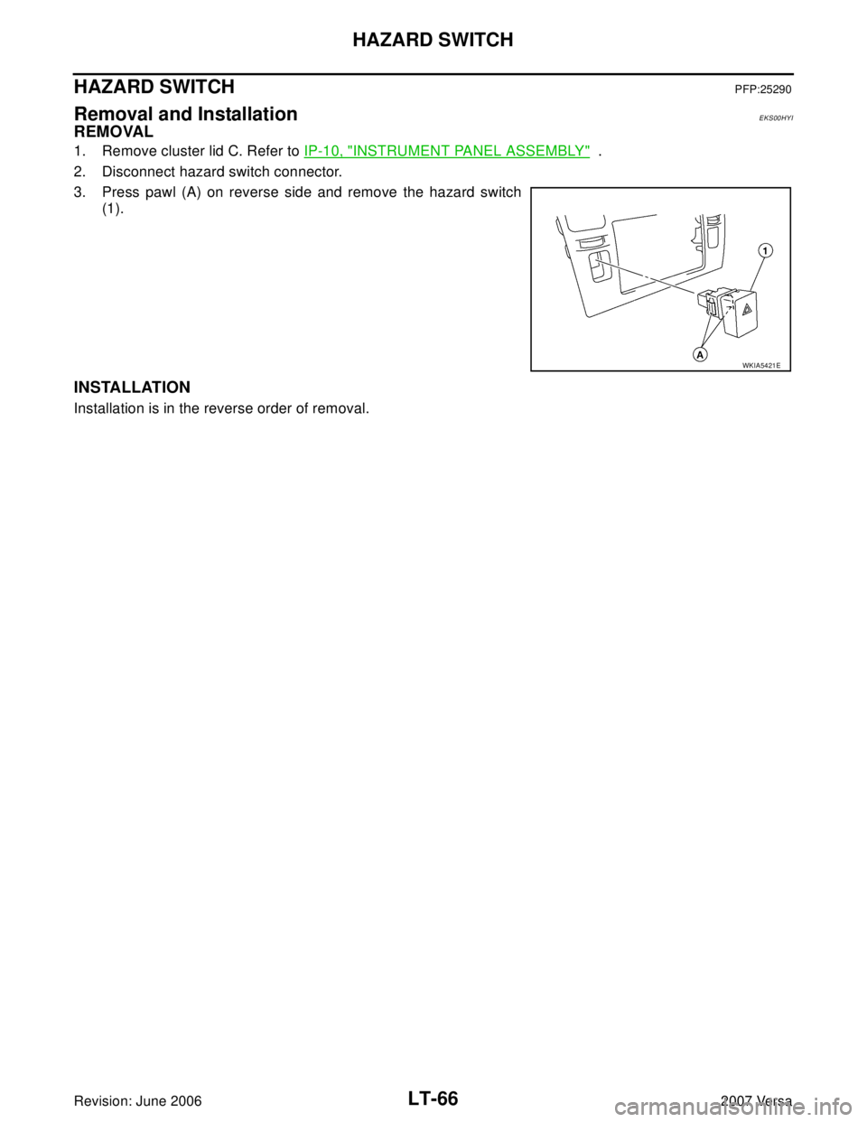
1. Remove cluster lid C. Refer to IP-10, "INSTRUMENT PANEL ASSEMBLY" .
2. Disconnect hazard switch connector.
3. Press pawl (A) on reverse side and remove the hazard switch
(1).
INSTALLATION
Installation is in the reverse order of removal.
WKIA5421E
Page 2473 of 2896
CONTROLLER
MTC-61
C
D
E
F
G
H
I
K
L
MA
B
MTC
Revision: June 20062007 Versa
CONTROLLERPFP:28074
Removal and InstallationEJS00580
REMOVAL
1. Remove cluster lid C and instrument finisher D. Refer to IP-10, "INSTRUMENT PANEL ASSEMBLY" .
2. Remove intake door lever knob. Refer to MTC-62, "
Disassembly
and Assembly" .
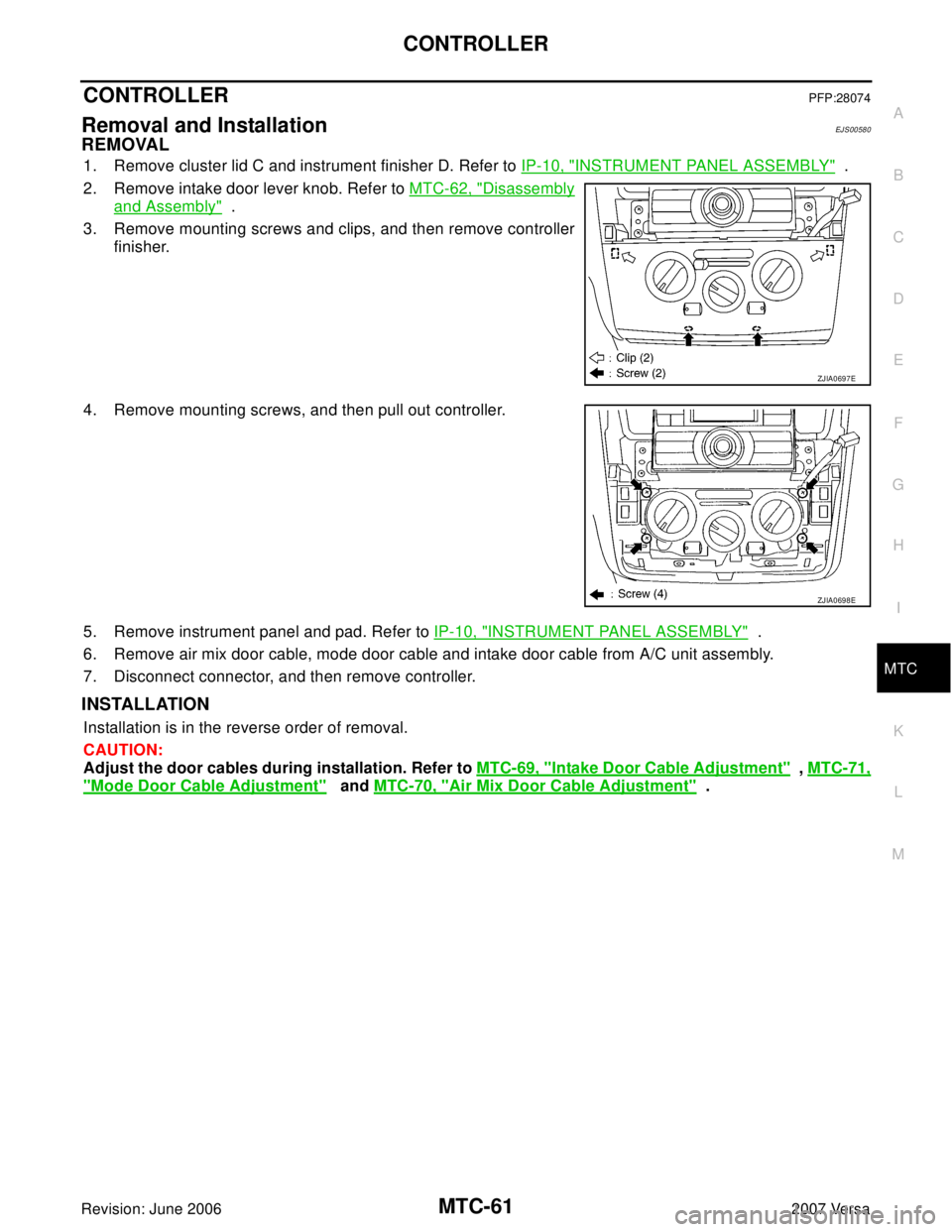
3. Remove mounting screws and clips, and then remove controller
finisher.
4. Remove mounting screws, and then pull out controller.
5. Remove instrument panel and pad. Refer to IP-10, "
INSTRUMENT PANEL ASSEMBLY" .
6. Remove air mix door cable, mode door cable and intake door cable from A/C unit assembly.
7. Disconnect connector, and then remove controller.
INSTALLATION
Installation is in the reverse order of removal.
CAUTION:
Adjust the door cables during installation. Refer to MTC-69, "
Intake Door Cable Adjustment" , MTC-71,
"Mode Door Cable Adjustment" and MTC-70, "Air Mix Door Cable Adjustment" .
ZJIA0697E
ZJIA0698E
Page 2487 of 2896
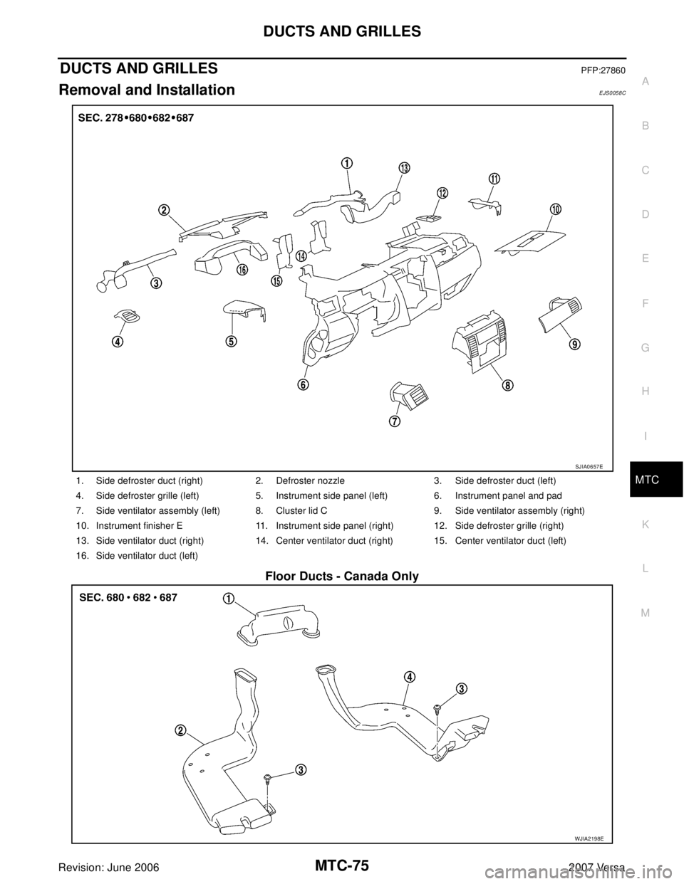
DUCTS AND GRILLES
MTC-75
C
D
E
F
G
H
I
K
L
MA
B
MTC
Revision: June 20062007 Versa
DUCTS AND GRILLESPFP:27860
Removal and InstallationEJS0058C
Floor Ducts - Canada Only
1. Side defroster duct (right) 2. Defroster nozzle 3. Side defroster duct (left)
4. Side defroster grille (left) 5. Instrument side panel (left) 6. Instrument panel and pad
7. Side ventilator assembly (left) 8. Cluster lid C 9. Side ventilator assembly (right)
10. Instrument finisher E 11. Instrument side panel (right) 12. Side defroster grille (right)
13. Side ventilator duct (right) 14. Center ventilator duct (right) 15. Center ventilator duct (left)
16. Side ventilator duct (left)
SJIA0657E
WJIA2198E
Page 2488 of 2896

MTC-76
DUCTS AND GRILLES
Revision: June 20062007 Versa
CENTER VENTILATOR GRILLES
Removal
1. Remove cluster lid C. Refer to IP-10, "INSTRUMENT PANEL ASSEMBLY" .
2. Remove center ventilator grills (1) from cluster lid C using suit-
able tool (A).
Installation
Installation is in the reverse order of removal.
SIDE VENTILATOR GRILLES (LH/RH)
Removal
1. Remove side ventilator assembly (LH). Refer to IP-10, "INSTRUMENT PANEL ASSEMBLY" .
2. Remove side ventilator grille (LH) (1) using suitable tool (A).
3. Remove side ventilator assembly (RH). Refer to IP-10, "
INSTRUMENT PANEL ASSEMBLY" .
4. Remove side ventilator grille (RH) (1) using suitable tool (A).
Installation
Installation is in the reverse order of removal.
1. Front floor duct 2. Rear floor duct (left) 3. Clip
4. Rear floor duct (right)
ZJIA0661E
SJIA0658E
SJIA0659E
Page 2624 of 2896
RF-6
SQUEAK AND RATTLE TROUBLE DIAGNOSES
Revision: June 20062007 Versa
FELT CLOTH TAPE
Used to insulate where movement does not occur. Ideal for instrument panel applications.
68370-4B000: 15 × 25 mm (0.59 × 0.98 in) pad/68239-13E00: 5 mm (0.20 in) wide tape roll
The following materials, not available through NISSAN Parts Department, can also be used to repair squeaks
and rattles.
UHMW(TEFLON) TAPE
Insulates where slight movement is present. Ideal for instrument panel applications.
SILICONE GREASE
Used in place of UHMW tape that will be visible or not fit.
Note: Will only last a few months.
SILICONE SPRAY
Use when grease cannot be applied.
DUCT TAPE
Use to eliminate movement.
CONFIRM THE REPAIR
Confirm that the cause of a noise is repaired by test driving the vehicle. Operate the vehicle under the same
conditions as when the noise originally occurred. Refer to the notes on the Diagnostic Worksheet.
Generic Squeak and Rattle TroubleshootingEIS009ON
Refer to Table of Contents for specific component removal and installation information.
INSTRUMENT PANEL
Most incidents are caused by contact and movement between:
1. The cluster lid A and instrument panel
2. Acrylic lens and combination meter housing
3. Instrument panel to front pillar garnish
4. Instrument panel to windshield
5. Instrument panel pins
6. Wiring harnesses behind the combination meter
7. A/C defroster duct and duct joint
These incidents can usually be located by tapping or moving the components to duplicate the noise or by
pressing on the components while driving to stop the noise. Most of these incidents can be repaired by apply-
ing felt cloth tape or silicone spray (in hard to reach areas). Urethane pads can be used to insulate wiring har-
ness.
CAUTION:
Do not use silicone spray to isolate a squeak or rattle. If you saturate the area with silicone, you will
not be able to recheck the repair.
CENTER CONSOLE
Components to pay attention to include:
1. Shifter assembly cover to finisher
2. A/C control unit and cluster lid C
3. Wiring harnesses behind audio and A/C control unit
The instrument panel repair and isolation procedures also apply to the center console.
DOORS
Pay attention to the:
1. Finisher and inner panel making a slapping noise
2. Inside handle escutcheon to door finisher
3. Wiring harnesses tapping
4. Door striker out of alignment causing a popping noise on starts and stops
Tapping or moving the components or pressing on them while driving to duplicate the conditions can isolate
many of these incidents. You can usually insulate the areas with felt cloth tape or insulator foam blocks from
the NISSAN Squeak and Rattle Kit (J-43980) to repair the noise.
Page 2714 of 2896
SE-6
SQUEAK AND RATTLE TROUBLE DIAGNOSES
Revision: June 20062007 Versa
80845-71L00: 30 mm (1.18 in) thick, 30×50 mm (1.18×1.97 in)
FELT CLOTH TAPE
Used to insulate where movement does not occur. Ideal for instrument panel applications.
68370-4B000: 15×25 mm (0.59×0.98 in) pad/68239-13E00: 5 mm (0.20 in) wide tape roll. The following
materials not found in the kit can also be used to repair squeaks and rattles.
UHMW (TEFLON) TAPE
Insulates where slight movement is present. Ideal for instrument panel applications.
SILICONE GREASE
Used instead of UHMW tape that will be visible or not fit.
Note: Will only last a few months.
SILICONE SPRAY
Use when grease cannot be applied.
DUCT TAPE
Use to eliminate movement.
CONFIRM THE REPAIR
Confirm that the cause of a noise is repaired by test driving the vehicle. Operate the vehicle under the same
conditions as when the noise originally occurred. Refer to the notes on the Diagnostic Worksheet.
Generic Squeak and Rattle TroubleshootingEIS009AR
Refer to Table of Contents for specific component removal and installation information.
INSTRUMENT PANEL
Most incidents are caused by contact and movement between:
1. The cluster lid A and instrument panel
2. Acrylic lens and combination meter housing
3. Instrument panel to front pillar garnish
4. Instrument panel to windshield
5. Instrument panel mounting pins
6. Wiring harnesses behind the combination meter
7. A/C defroster duct and duct joint
These incidents can usually be located by tapping or moving the components to duplicate the noise or by
pressing on the components while driving to stop the noise. Most of these incidents can be repaired by apply-
ing felt cloth tape or silicone spray (in hard to reach areas). Urethane pads can be used to insulate wiring har-
ness.
CAUTION:
Do not use silicone spray to isolate a squeak or rattle. If you saturate the area with silicone, you will
not be able to recheck the repair.
CENTER CONSOLE
Components to pay attention to include:
1. Shifter assembly cover to finisher
2. A/C control unit and cluster lid C
3. Wiring harnesses behind audio and A/C control unit
The instrument panel repair and isolation procedures also apply to the center console.
DOORS
Pay attention to the:
1. Finisher and inner panel making a slapping noise
2. Inside handle escutcheon to door finisher
3. Wiring harnesses tapping
4. Door striker out of alignment causing a popping noise on starts and stops
Tapping or moving the components or pressing on them while driving to duplicate the conditions can isolate
many of these incidents. You can usually insulate the areas with felt cloth tape or insulator foam blocks from
the NISSAN Squeak and Rattle Kit (J-43980) to repair the noise.