fog light NISSAN VERSA NOTE 2018 Owner´s Manual
[x] Cancel search | Manufacturer: NISSAN, Model Year: 2018, Model line: VERSA NOTE, Model: NISSAN VERSA NOTE 2018Pages: 878, PDF Size: 9.62 MB
Page 12 of 878
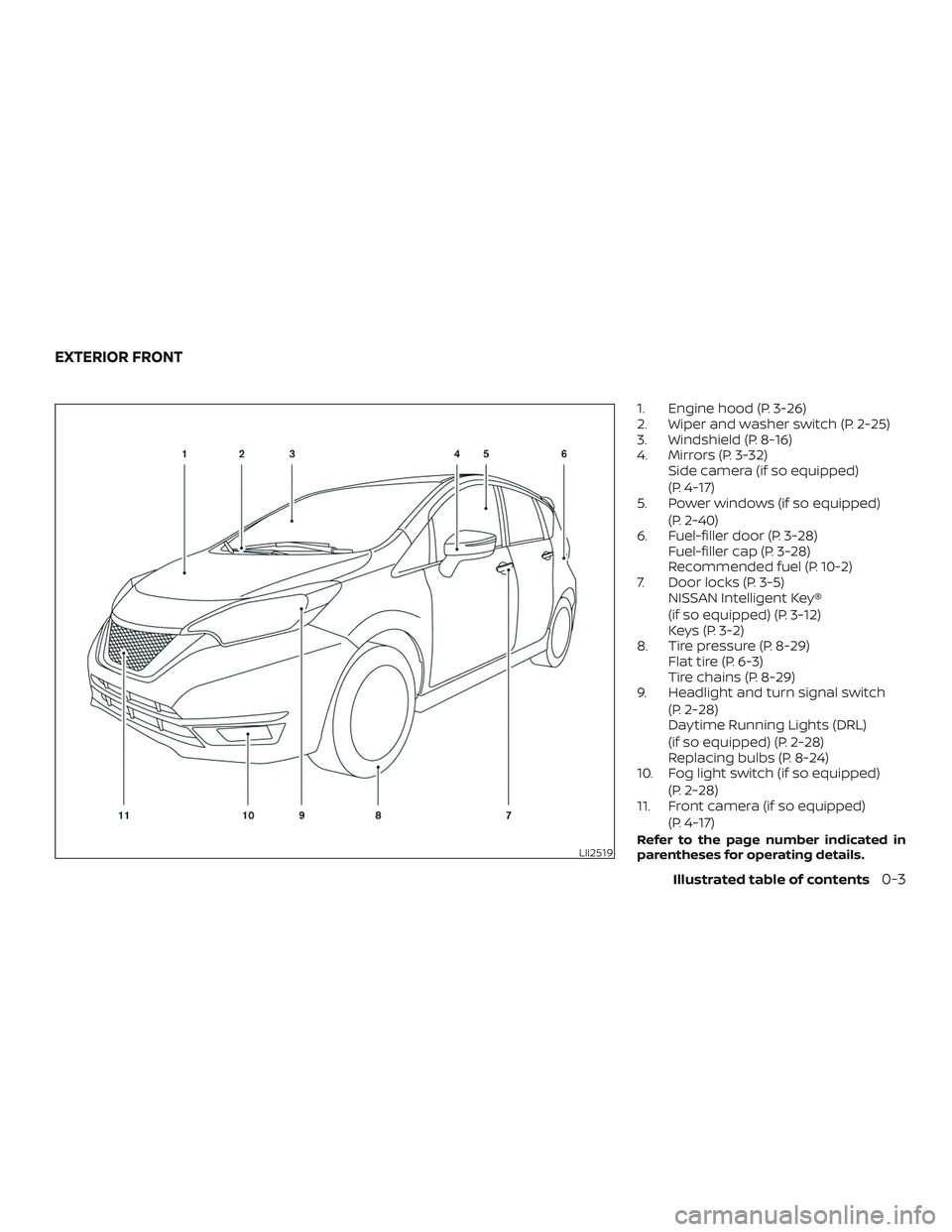
1. Engine hood (P. 3-26)
2. Wiper and washer switch (P. 2-25)
3. Windshield (P. 8-16)
4. Mirrors (P. 3-32)Side camera (if so equipped)
(P. 4-17)
5. Power windows (if so equipped)
(P. 2-40)
6. Fuel-filler door (P. 3-28) Fuel-filler cap (P. 3-28)
Recommended fuel (P. 10-2)
7. Door locks (P. 3-5) NISSAN Intelligent Key®
(if so equipped) (P. 3-12)
Keys (P. 3-2)
8. Tire pressure (P. 8-29) Flat tire (P. 6-3)
Tire chains (P. 8-29)
9. Headlight and turn signal switch
(P. 2-28)
Daytime Running Lights (DRL)
(if so equipped) (P. 2-28)
Replacing bulbs (P. 8-24)
10. Fog light switch (if so equipped)
(P. 2-28)
11. Front camera (if so equipped)
(P. 4-17)
Refer to the page number indicated in
parentheses for operating details.LII2519
EXTERIOR FRONT
Illustrated table of contents0-3
Page 15 of 878
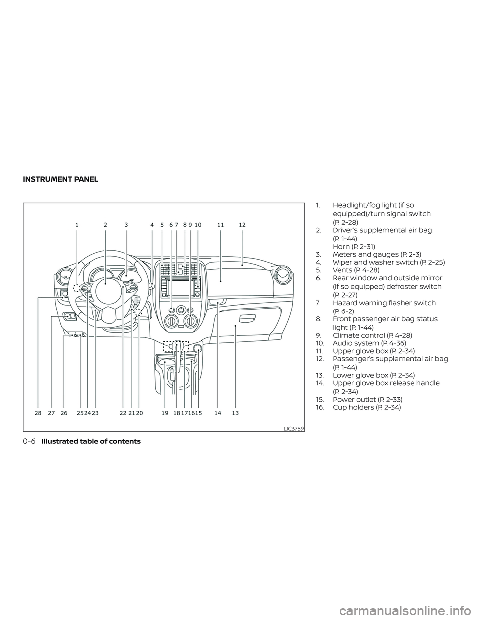
1. Headlight/fog light (if soequipped)/turn signal switch
(P. 2-28)
2. Driver’s supplemental air bag
(P. 1-44)
Horn (P. 2-31)
3. Meters and gauges (P. 2-3)
4. Wiper and washer switch (P. 2-25)
5. Vents (P. 4-28)
6. Rear window and outside mirror
(if so equipped) defroster switch
(P. 2-27)
7. Hazard warning flasher switch
(P. 6-2)
8. Front passenger air bag status
light (P. 1-44)
9. Climate control (P. 4-28)
10. Audio system (P. 4-36)
11. Upper glove box (P. 2-34)
12. Passenger’s supplemental air bag
(P. 1-44)
13. Lower glove box (P. 2-34)
14. Upper glove box release handle
(P. 2-34)
15. Power outlet (P. 2-33)
16. Cup holders (P. 2-34)
LIC3759
INSTRUMENT PANEL
0-6Illustrated table of contents
Page 19 of 878
Indicatorlight Name Page
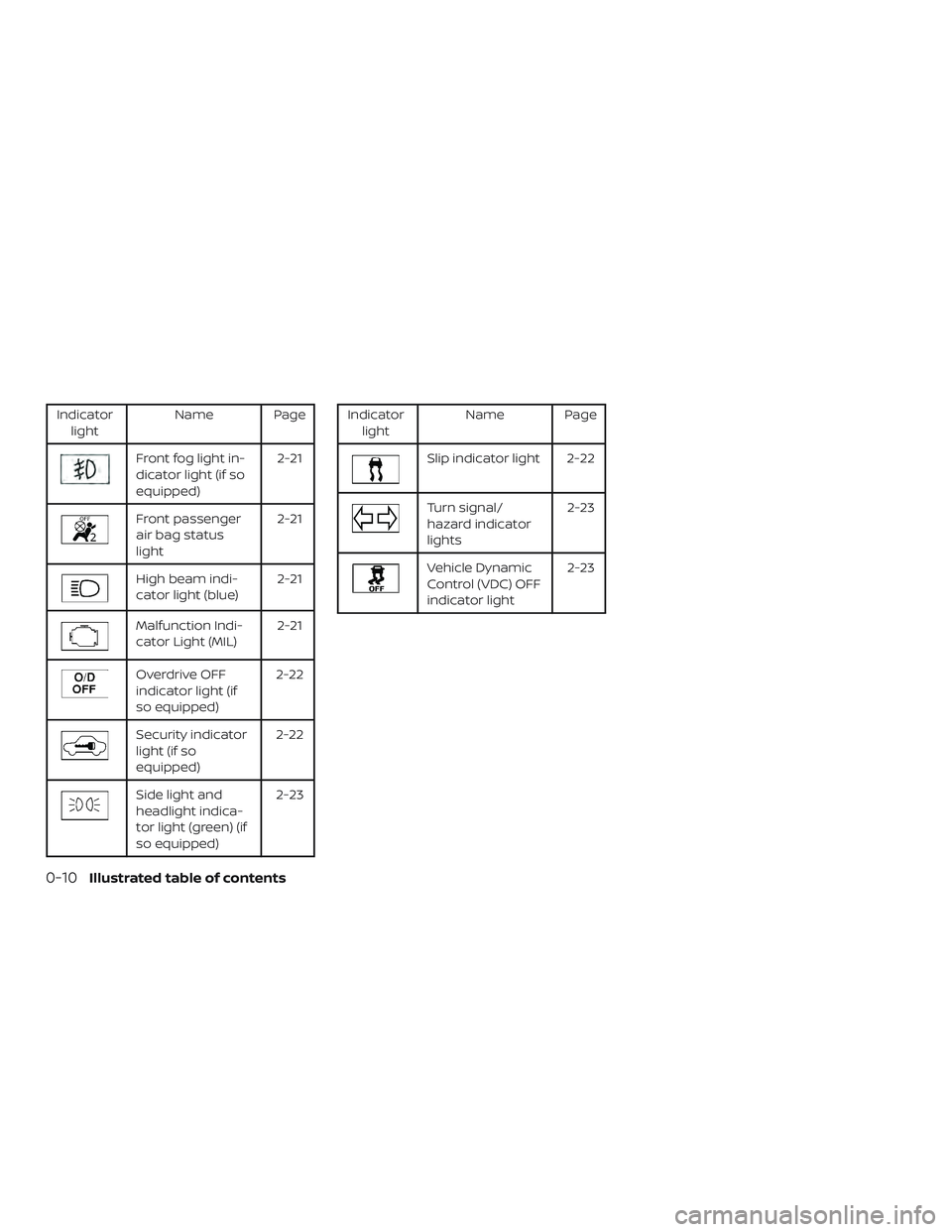
Front fog light in-
dicator light (if so
equipped) 2-21
Front passenger
air bag status
light2-21
High beam indi-
cator light (blue)
2-21
Malfunction Indi-
cator Light (MIL)2-21
Overdrive OFF
indicator light (if
so equipped)2-22
Security indicator
light (if so
equipped)2-22
Side light and
headlight indica-
tor light (green) (if
so equipped) 2-23
Indicator
light Name Page
Slip indicator light 2-22
Turn signal/
hazard indicator
lights 2-23
Vehicle Dynamic
Control (VDC) OFF
indicator light2-23
0-10Illustrated table of contents
Page 84 of 878
2 Instruments and controls
Instrument panel................................2-2
Meters and gauges ..............................2-3
Speedometer and odometer .................2-5
Tachometer ..................................2-8
Engine coolant temperature gauge ..........2-9
Fuel gauge .................................. 2-10
Trip computer ................................ 2-11
Service interval reminder
(if so equipped) .............................. 2-12
Warning lights, indicator lights and audible
reminders ...................................... 2-14
Checking lights .............................. 2-15
Warning lights ............................... 2-15
Indicator lights .............................. 2-20
Audible reminders ........................... 2-23
Security systems ............................... 2-24
NISSAN Vehicle Immobilizer System
(if so equipped) .............................. 2-24
Wiper and washer switch .......................2-25
Switch operation ............................ 2-25
Rear switch operation .......................2-26
Rear window and outside mirror
(if so equipped) defroster switch ................2-27
Headlight and turn signal switch ...............2-28
Headlight control switch .....................2-28Daytime running light (DRL) system
(Canada only)
................................ 2-29
Instrument brightness control ...............2-29
Turn signal switch ........................... 2-30
Fog light switch (if so equipped) .............2-31
Horn ........................................... 2-31
Heated seat switches (if so equipped) ..........2-32
Vehicle Dynamic Control (VDC) OFF switch ......2-33
Power outlets .................................. 2-33
Storage ........................................ 2-34
Front-door pockets .......................... 2-34
Seatback pocket ............................ 2-35
Storagetray................................. 2-35
Glovebox.................................... 2-36
Upper glove box ............................. 2-36
Cup holders ................................. 2-36
Divide-n-hide®
adjustable floor
(if so equipped) .............................. 2-38
Cargo cover (if so equipped) .................2-39
Windows ....................................... 2-40
Power windows (if so equipped) .............2-40
Manual windows (if so equipped) ............2-42
Interior lights ................................... 2-42
Map light .................................... 2-43
Luggage compartment light ...................2-44
Page 85 of 878
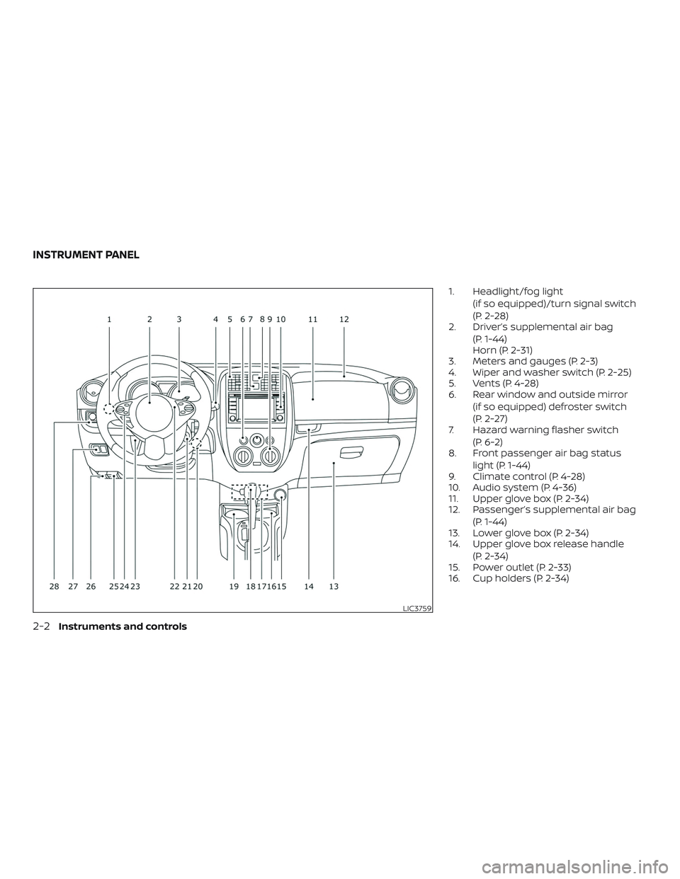
1. Headlight/fog light(if so equipped)/turn signal switch
(P. 2-28)
2. Driver’s supplemental air bag
(P. 1-44)
Horn (P. 2-31)
3. Meters and gauges (P. 2-3)
4. Wiper and washer switch (P. 2-25)
5. Vents (P. 4-28)
6. Rear window and outside mirror
(if so equipped) defroster switch
(P. 2-27)
7. Hazard warning flasher switch
(P. 6-2)
8. Front passenger air bag status
light (P. 1-44)
9. Climate control (P. 4-28)
10. Audio system (P. 4-36)
11. Upper glove box (P. 2-34)
12. Passenger’s supplemental air bag
(P. 1-44)
13. Lower glove box (P. 2-34)
14. Upper glove box release handle
(P. 2-34)
15. Power outlet (P. 2-33)
16. Cup holders (P. 2-34)
LIC3759
INSTRUMENT PANEL
2-2Instruments and controls
Page 97 of 878
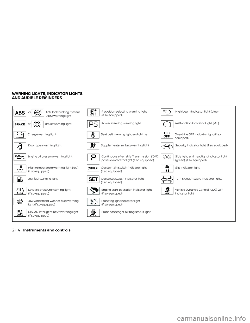
orAnti-lock Braking System
(ABS) warning lightP position selecting warning light
(if so equipped)High beam indicator light (blue)
orBrake warning lightPower steering warning lightMalfunction Indicator Light (MIL)
Charge warning lightSeat belt warning light and chimeOverdrive OFF indicator light (if so
equipped)
Door open warning lightSupplemental air bag warning lightSecurity indicator light (if so equipped)
Engine oil pressure warning lightContinuously Variable Transmission (CVT)
position indicator light (if so equipped)Side light and headlight indicator light
(green) (if so equipped)
High temperature warning light (red)
(if so equipped)Cruise main switch indicator light
(if so equipped)Slip indicator light
Low fuel warning lightCruise set switch indicator light
(if so equipped)Turn signal/hazard indicator lights
Low tire pressure warning light
(if so equipped)Engine start operation indicator light
(if so equipped)Vehicle Dynamic Control (VDC) OFF
indicator light
Low windshield-washer fluid warning
light (if so equipped)Front fog light indicator light
(if so equipped)
NISSAN Intelligent Key® warning light
(if so equipped)Front passenger air bag status light
WARNING LIGHTS, INDICATOR LIGHTS
AND AUDIBLE REMINDERS
2-14Instruments and controls
Page 104 of 878
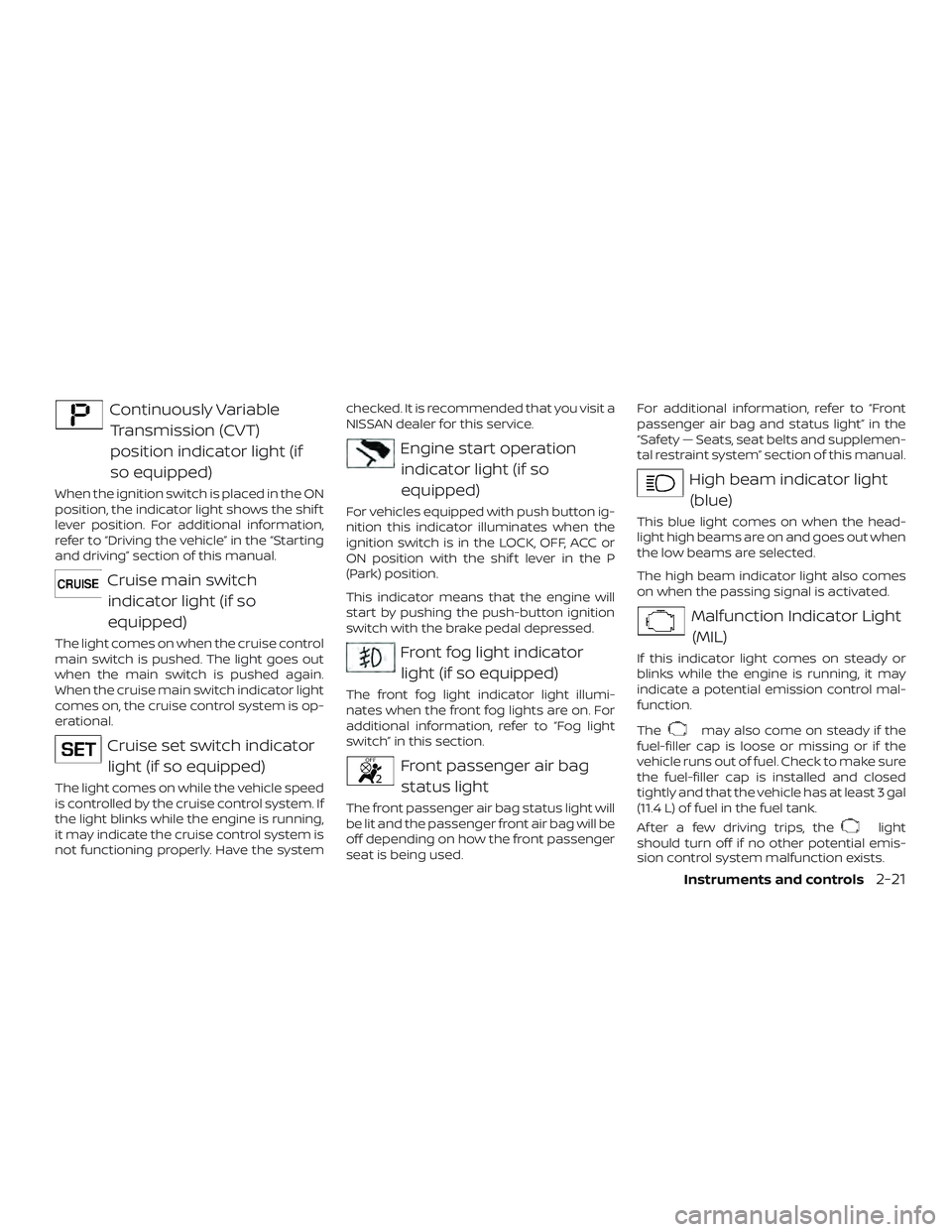
Continuously VariableTransmission (CVT)
position indicator light (if
so equipped)
When the ignition switch is placed in the ON
position, the indicator light shows the shif t
lever position. For additional information,
refer to “Driving the vehicle” in the “Starting
and driving” section of this manual.
Cruise main switchindicator light (if so
equipped)
The light comes on when the cruise control
main switch is pushed. The light goes out
when the main switch is pushed again.
When the cruise main switch indicator light
comes on, the cruise control system is op-
erational.
Cruise set switch indicatorlight (if so equipped)
The light comes on while the vehicle speed
is controlled by the cruise control system. If
the light blinks while the engine is running,
it may indicate the cruise control system is
not functioning properly. Have the system checked. It is recommended that you visit a
NISSAN dealer for this service.
Engine start operation
indicator light (if so
equipped)
For vehicles equipped with push button ig-
nition this indicator illuminates when the
ignition switch is in the LOCK, OFF, ACC or
ON position with the shif t lever in the P
(Park) position.
This indicator means that the engine will
start by pushing the push-button ignition
switch with the brake pedal depressed.
Front fog light indicatorlight (if so equipped)
The front fog light indicator light illumi-
nates when the front fog lights are on. For
additional information, refer to “Fog light
switch” in this section.
Front passenger air bagstatus light
The front passenger air bag status light will
be lit and the passenger front air bag will be
off depending on how the front passenger
seat is being used. For additional information, refer to “Front
passenger air bag and status light” in the
“Safety — Seats, seat belts and supplemen-
tal restraint system” section of this manual.
High beam indicator light
(blue)
This blue light comes on when the head-
light high beams are on and goes out when
the low beams are selected.
The high beam indicator light also comes
on when the passing signal is activated.
Malfunction Indicator Light(MIL)
If this indicator light comes on steady or
blinks while the engine is running, it may
indicate a potential emission control mal-
function.
The
may also come on steady if the
fuel-filler cap is loose or missing or if the
vehicle runs out of fuel. Check to make sure
the fuel-filler cap is installed and closed
tightly and that the vehicle has at least 3 gal
(11.4 L) of fuel in the fuel tank.
Af ter a few driving trips, the
light
should turn off if no other potential emis-
sion control system malfunction exists.
Instruments and controls2-21
Page 114 of 878
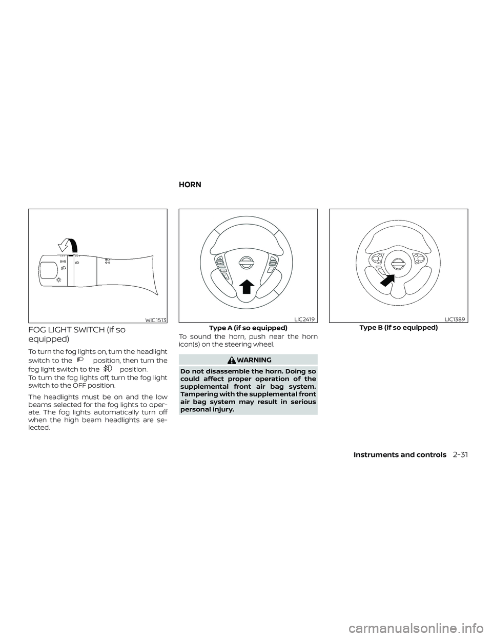
FOG LIGHT SWITCH (if so
equipped)
To turn the fog lights on, turn the headlight
switch to the
position, then turn the
fog light switch to the
position.
To turn the fog lights off, turn the fog light
switch to the OFF position.
The headlights must be on and the low
beams selected for the fog lights to oper-
ate. The fog lights automatically turn off
when the high beam headlights are se-
lected. To sound the horn, push near the horn
icon(s) on the steering wheel.
WARNING
Do not disassemble the horn. Doing so
could affect proper operation of the
supplemental front air bag system.
Tampering with the supplemental front
air bag system may result in serious
personal injury.
WIC1513
Type A (if so equipped)
LIC2419
Type B (if so equipped)
LIC1389
HORN
Instruments and controls2-31
Page 191 of 878
— Air flows from defroster outletsand foot outlets.
— Air flows mainly from defrosteroutlets.
Temperature control dial
The temperature control dial allows you to
adjust the temperature of the outlet air. To
lower the temperature, turn the dial to the
lef t. To increase the temperature, turn the
dial to the right.
Fresh air
Move the air intake lever to theposi-
tion. The air flow is drawn from outside the
vehicle.
Air recirculation
Move the air intake lever to theposi-
tion to recirculate air inside the vehicle.
Use the
selection:
∙ when driving on a dusty road.
∙ to prevent traffic fumes from entering passenger compartment.
∙ for maximum cooling when using the air conditioner.
Air conditioner button
Start the engine, turn the fan control dial to
the desired position and press the
button to turn on the air conditioner. The
indicator light comes on when the air con-
ditioner is operating. To turn off the air con-
ditioner, press the
button again.
The air conditioner cooling function op-
erates only when the engine is running.
Rear window and outside mirror
(if so equipped) defroster switch
For additional information, refer to “Rear
window and outside mirror (if so equipped)
defroster switch” in the “Instruments and
controls” section of this manual.
HEATER OPERATION
Heating
This mode is used to direct heated air to
the foot outlets. Some air also flows from
the defrost outlets.
1. Move the air intake lever to the
position for normal heating.
2. Turn the air flow control dial to the
position. 3. Turn the
fan control dial to the
desired position.
4. Turn the temperature control dial to the desired position between the
middle and the hot position.
Ventilation
This mode directs outside air to the side
and center vents.
1. Move the air intake lever to the
position.
2. Turn the air flow control dial to the
position.
3. Turn the
fan control dial to the
desired position.
4. Turn the temperature control dial to the desired position.
Defrosting or defogging
This mode directs the air to the defrost
outlets to defrost/defog the windows.
1. Move the air intake lever to the
position.
2. Turn the air flow control dial to the
position.
4-30Monitor, climate, audio, phone and voice recognition systems
Page 192 of 878
3. Turn thefan control dial to the de-
sired position.
4. Turn the temperature control dial to the desired position between the
middle and the hot position.
∙ To quickly remove ice or fog from the windows, turn the fan control dial to the
maximum position and the tempera-
ture control dial to the full hot position.
∙ For additional information on how to optimize defogging performance, refer
to the advice label on the sun visor.
When the
orposition is se-
lected, press the
button to turn on
the air conditioner for better performance.
This will dehumidif y the air and help defog
the windows.
Bi-level heating
This mode directs cooler air from the side
and center vents and warmer air from the
floor outlets. When the temperature con-
trol dial is moved to the full hot or full cool
position, the air between the vents and the
floor outlets is the same temperature.
1. Move the air intake lever to the
position. 2. Turn the air flow control dial to
the
position.
3. Turn the
fan control dial to the
desired position.
4. Turn the temperature control dial to the desired position.
Heating and defogging
This mode heats the interior and defogs
the windshield.
1. Move the air intake lever to the
position.
2. Turn the air flow control dial to the
position.
3. Turn the
fan control dial to the de-
sired position.
4. Turn the temperature control dial to the desired position between the
middle and the hot position.
∙ When
orare selected, the air
conditioner turns on (the indicator light
may not illuminate). This will dehumidif y
the air and help defog the windows.
Operating tips
Clear snow and ice from the wiper blades
and air inlet in front of the windshield.
This improves heater operation.
AIR CONDITIONER OPERATION
Start the engine, turn thefan control
dial to the desired position, and press
the
button to activate the air condi-
tioner. When the air conditioner is on, cool-
ing and dehumidif ying functions are
added to the heater operation.
The air conditioner cooling function op-
erates only when the engine is running.
Cooling
This mode is used to cool and dehumidif y
the air.
1. Move the air intake lever to the
position.
2. Turn the air flow control dial to the
position.
3. Turn the
fan control dial to the
desired position.
4. Press the
button. The indicator
light comes on.
Monitor, climate, audio, phone and voice recognition systems4-31