check engine NISSAN X-TRAIL 2001 Service Repair Manual
[x] Cancel search | Manufacturer: NISSAN, Model Year: 2001, Model line: X-TRAIL, Model: NISSAN X-TRAIL 2001Pages: 3833, PDF Size: 39.49 MB
Page 3811 of 3833

ENGINE MAINTENANCE (YD22DDTI)
MA-31
C
D
E
F
G
H
I
J
K
MA
B
MA
Changing Fuel FilterELS000CF
REMOVAL
1. Remove air duct and upper air cleaner case.
2. Remove fuel filter protector.
3. Remove fuel hoses from fuel filter bracket.
CAUTION:
Plug the pipe to prevent fuel from draining.
4. Remove fuel filter with bracket.
CAUTION:
Do not splash fuel during removal. If fuel is splashed,
immediately wipe it off.
5. Using band-type filter wrench (commercial service tool), remove
fuel filter.
6. Turn fuel filter upside down to drain fuel.
7. Remove drain plug from fuel filter.
INSTALLATION
Install in reverse order of removal, paying attention to following:
●Replace O-ring on drain plug with new one.
●Screw the fuel filter by hand until packing contacts sealing surface of bracket. Then tighten it by turning
approximately 2/3 turn.
●After installation, bleed air from fuel path. Refer to FL-16, "Air Bleeding" .
●Check for fuel leakage with running engine.
SBIA0134E
SBIA0135E
SBIA0136E
Fuel filter drain plug:
: 3.9 - 5.9 N·m (0.4 - 0.6 kg-m, 35 - 52 in-lb)
Page 3812 of 3833

MA-32
ENGINE MAINTENANCE (YD22DDTI)
Changing Air Cleaner Filter
ELS000CG
VISCOUS PAPER TYPE
The viscous paper type air cleaner filter does not require any clean-
ing operation between renewal.
Changing Engine OilELS000CH
WARNING:
●Be careful not to burn yourself, as the engine oil is hot.
●Prolonged and repeated contact with used engine oil may
cause skin cancer: try to avoid direct skin contact with
used engine oil. If skin contact is made, wash thoroughly
with soap or hand cleaner as soon as possible.
1. Warm up engine, put vehicle horizontally and check for engine
oil leakage from engine components.
2. Stop engine and wait for 10 minutes.
3. Remove drain plug and oil filler cap.
4. Drain engine oil.
●Install drain plug and refill with new engine oil.
Engine oil specification and viscosity:
●API grade CF-4.
●ACEA B1, B3, B4, B5
●Refer to MA-16, "RECOMMENDED FLUIDS AND LUBRI-
CANTS" .
Engine oil capacity (Approximate):
●The refill capacity depends on the engine oil temperature and drain time. Use these specifications for
reference only.
Always use the dipstick to the determine when the proper amount of engine oil is in the engine.
CAUTION:
●Be sure to clean drain plug and install with new washer.
●The refill capacity depends on the engine oil temperature and drain time. Use these specifica-
tions for reference only.
Always use the dipstick to the determine when the proper amount of engine oil is in the
engine.
5. Warm up engine and check area around drain plug and oil filter for engine oil leakage.
6. Stop engine and wait for 10 minutes.
7. Check engine oil level. Refer to LU-18, "
ENGINE OIL" .
PBIC0526E
PBIC0527E
Drain and refillWith oil filter change
5.2 (4-5/8 Imp qt)
Without oil filter change
4.9 (4-3/8 Imp qt)
Dry engine (engine overhaul)6.3 (5-1/2 Imp qt)
Oil pan drain plug:
: 29 - 39 N·m (3.0 - 4.0 kg-m, 22 - 29 ft-lb)
SBIA0122E
Page 3814 of 3833

MA-34
ENGINE MAINTENANCE (YD22DDTI)
4. Remove the O-ring from the filter body.
●Push the O-ring in one direction, lift the slack part using fin-
gers, and remove the O-ring from the filter body.
CAUTION:
Do not use wires or flat-bladed screwdrivers etc. as they
may cause damage to the filter body.
INSTALLATION
1. Completely remove all foreign objects adhering to the inside of the filter body or O-ring mounting area
(body side and bracket side).
2. Install the oil filter and O-ring to the filter body.
●Push the oil filter into the filter body completely.
3. Install the filter body to the oil filter bracket.
4. After warming up the engine, check for engine oil leakage.
5. Check engine oil level and add engine oil. Refer to LU-18, "
ENGINE OIL" .
Draining WaterELS000CJ
1. Prepare a tray at the drain hose open end.
2. Loosen drain cock, and operate priming pump to drain water
from fuel filter.
CAUTION:
●Water in filter is drained with fuel. Prepare larger capacity
pan than fuel filter volume.
●Drained water is mixed with fuel. Prevent fuel from adher-
ing to rubber parts such as engine mount insulator.
3. After draining, close drain cock by hand.
CAUTION:
If drain cock is tightened excessively, it may be damaged
and fuel will leak. Do not use tools to tighten drain cock.
4. Bleed air in fuel piping. Refer to FL-16, "
Air Bleeding" .
5. Start engine and check fuel leakage.
JLC292B
Oil filter:
: 20 - 24 N·m (2.0 - 2.5 Kg-m, 15 - 18 ft-lb)
SBIA0138E
Page 3815 of 3833
CHASSIS AND BODY MAINTENANCE
MA-35
C
D
E
F
G
H
I
J
K
MA
B
MA
CHASSIS AND BODY MAINTENANCEPFP:00100
Checking Exhaust SystemELS000B9
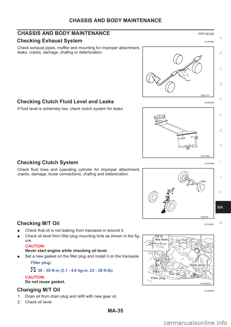
Check exhaust pipes, muffler and mounting for improper attachment,
leaks, cracks, damage, chafing or deterioration.
Checking Clutch Fluid Level and LeaksELS000BA
If fluid level is extremely low, check clutch system for leaks.
Checking Clutch SystemELS000BB
Check fluid lines and operating cylinder for improper attachment,
cracks, damage, loose connections, chafing and deterioration.
Checking M/T OilELS000BC
●Check that oil is not leaking from transaxle or around it.
●Check oil level from filler plug mounting hole as shown in the fig-
ure.
CAUTION:
Never start engine while checking oil level.
●Set a new gasket on the filler plug and install it on the transaxle.
CAUTION:
Do not reuse gasket.
Changing M/T OilELS000BD
1. Drain oil from drain plug and refill with new gear oil.
2. Check oil level.
SMA211A
SFIA0066J
SMA859
Filler plug:
: 30 - 39 N·m (3.1 - 4.0 kg-m, 23 - 28 ft-lb)
SCIA0361E
Page 3816 of 3833
MA-36
CHASSIS AND BODY MAINTENANCE
CAUTION:
Do not reuse gasket.
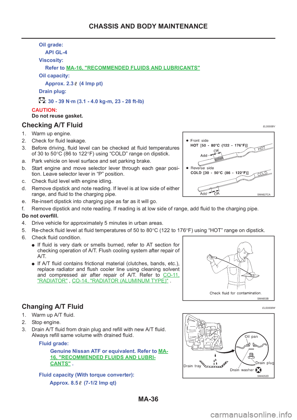
Checking A/T FluidELS000BV
1. Warm up engine.
2. Check for fluid leakage.
3. Before driving, fluid level can be checked at fluid temperatures
of 30 to 50°C (86 to 122°F) using “COLD” range on dipstick.
a. Park vehicle on level surface and set parking brake.
b. Start engine and move selector lever through each gear posi-
tion. Leave selector lever in “P” position.
c. Check fluid level with engine idling.
d. Remove dipstick and note reading. If level is at low side of either
range, and fluid to the charging pipe.
e. Re-insert dipstick into charging pipe as far as it will go.
f. Remove dipstick and note reading. If reading is at low side of range, add fluid to the charging pipe.
Do not overfill.
4. Drive vehicle for approximately 5 minutes in urban areas.
5. Re-check fluid level at fluid temperatures of 50 to 80°C (122 to 176°F) using “HOT” range on dipstick.
6. Check fluid condition.
●If fluid is very dark or smells burned, refer to AT section for
checking operation of A/T. Flush cooling system after repair of
A/T.
●If A/T fluid contains frictional material (clutches, bands, etc.),
replace radiator and flush cooler line using cleaning solvent
and compressed air after repair of A/T. Refer to CO-11,
"RADIATOR" , CO-14, "RADIATOR (ALUMINUM TYPE)" .
Changing A/T FluidELS000BW
1. Warm up A/T fluid.
2. Stop engine.
3. Drain A/T fluid from drain plug and refill with new A/T fluid.
Always refill same volume with drained fluid.Oil grade:
API GL-4
Viscosity:
Refer to MA-16, "
RECOMMENDED FLUIDS AND LUBRICANTS"
Oil capacity:
Approx. 2.3 (4 lmp pt)
Drain plug:
: 30 - 39 N·m (3.1 - 4.0 kg-m, 23 - 28 ft-lb)
SMA827CA
SMA853B
Fluid grade:
Genuine Nissan ATF or equivalent. Refer to MA-
16, "RECOMMENDED FLUIDS AND LUBRI-
CANTS" .
Fluid capacity (With torque converter):
Approx. 8.5 (7-1/2 lmp qt)
SMA052D
Page 3817 of 3833
CHASSIS AND BODY MAINTENANCE
MA-37
C
D
E
F
G
H
I
J
K
MA
B
MA
4. Run engine at idle speed for five minutes.
5. Check fluid level and condition. Refer to MA-36, "
Checking A/T Fluid" . If fluid is still dirty, repeat steps 2
through 5.
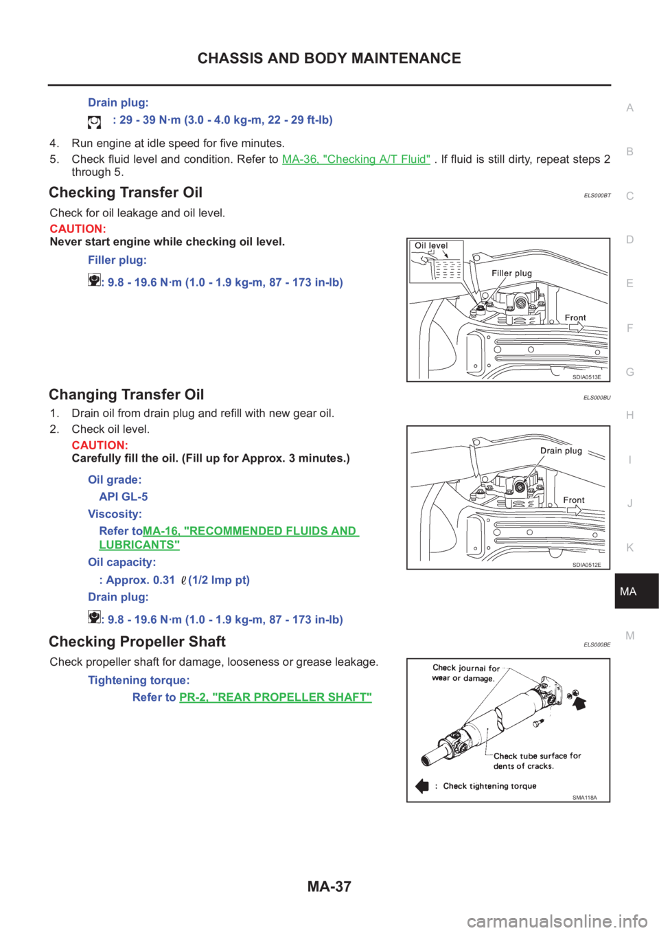
Checking Transfer OilELS000BT
Check for oil leakage and oil level.
CAUTION:
Never start engine while checking oil level.
Changing Transfer OilELS000BU
1. Drain oil from drain plug and refill with new gear oil.
2. Check oil level.
CAUTION:
Carefully fill the oil. (Fill up for Approx. 3 minutes.)
Checking Propeller ShaftELS000BE
Check propeller shaft for damage, looseness or grease leakage.Drain plug:
: 29 - 39 N·m (3.0 - 4.0 kg-m, 22 - 29 ft-lb)
Filler plug:
: 9.8 - 19.6 N·m (1.0 - 1.9 kg-m, 87 - 173 in-lb)
SDIA0513E
Oil grade:
API GL-5
Viscosity:
Refer toMA-16, "
RECOMMENDED FLUIDS AND
LUBRICANTS"
Oil capacity:
: Approx. 0.31 (1/2 lmp pt)
Drain plug:
: 9.8 - 19.6 N·m (1.0 - 1.9 kg-m, 87 - 173 in-lb)SDIA0512E
Tightening torque:
Refer to PR-2, "
REAR PROPELLER SHAFT"
SMA118A
Page 3820 of 3833
MA-40
CHASSIS AND BODY MAINTENANCE
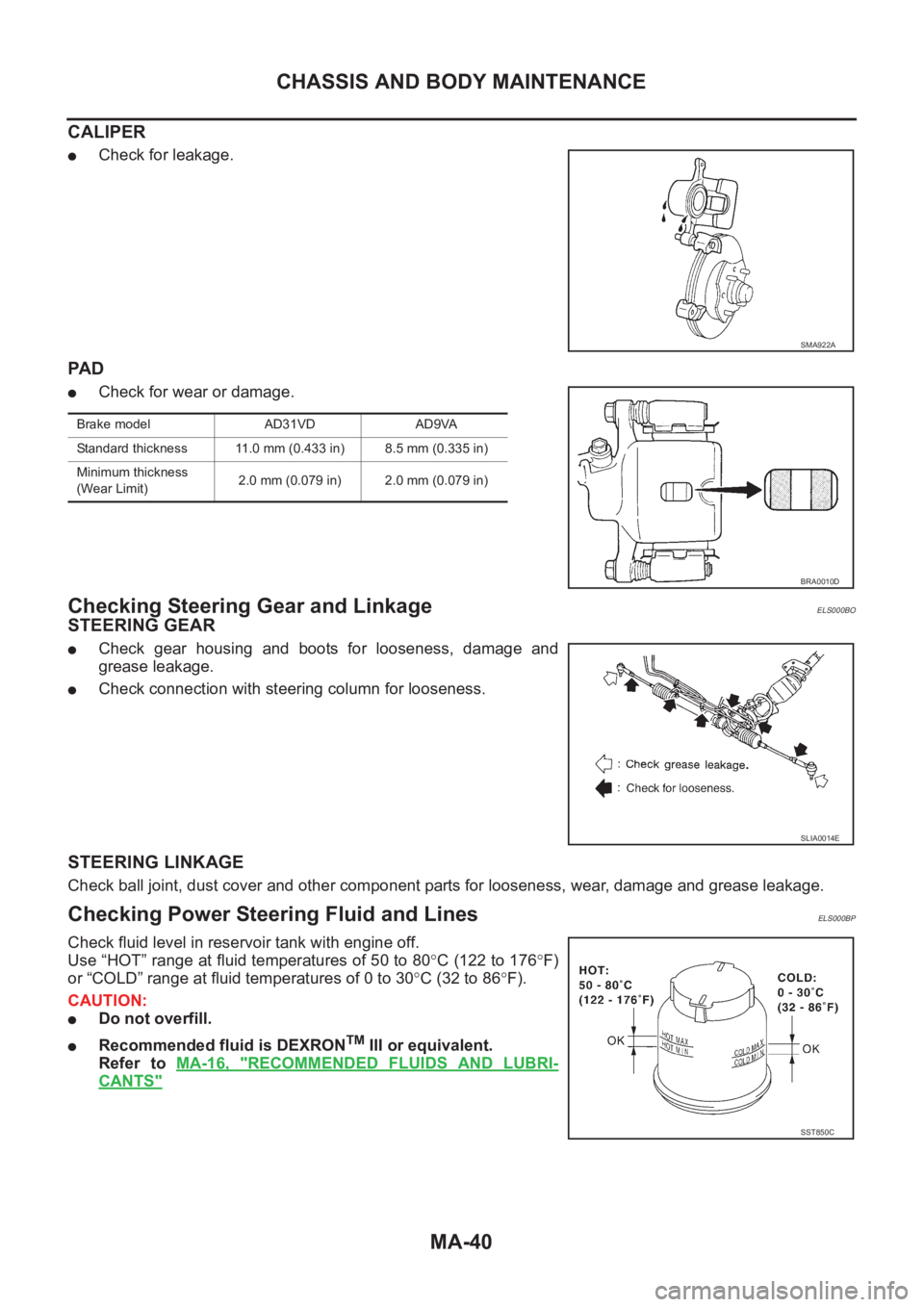
CALIPER
●Check for leakage.
PA D
●Check for wear or damage.
Checking Steering Gear and LinkageELS000BO
STEERING GEAR
●Check gear housing and boots for looseness, damage and
grease leakage.
●Check connection with steering column for looseness.
STEERING LINKAGE
Check ball joint, dust cover and other component parts for looseness, wear, damage and grease leakage.
Checking Power Steering Fluid and LinesELS000BP
Check fluid level in reservoir tank with engine off.
Use “HOT” range at fluid temperatures of 50 to 80°C (122 to 176°F)
or “COLD” range at fluid temperatures of 0 to 30°C (32 to 86°F).
CAUTION:
●Do not overfill.
●Recommended fluid is DEXRONTM III or equivalent.
Refer to MA-16, "
RECOMMENDED FLUIDS AND LUBRI-
CANTS"
SMA922A
Brake model AD31VD AD9VA
Standard thickness 11.0 mm (0.433 in) 8.5 mm (0.335 in)
Minimum thickness
(Wear Limit)2.0 mm (0.079 in) 2.0 mm (0.079 in)
BRA0010D
SLIA0014E
SST850C
Page 3822 of 3833

MA-42
CHASSIS AND BODY MAINTENANCE
Checking Seat Belts, Buckles, Retractors, Anchors and Adjusters
ELS000BS
Checking Body CorrosionELS000C0
Visually check body panels for collision damage (scratches, chipping, rubbing, etc.) or damage to the anti-cor-
rosion materials. In particular, check the following locations.
HEMMED PANELS
Hood front end, door lower end, trunk lid rear end, etc.
PANEL JOINT
Side sill of rear fender and center pillar, rear wheel housing of rear fender, around strut tower in engine com-
partment, etc.
PANEL EDGE
Trunk lid opening, sunroof opening, fender wheel-arch flange, fuel filler lid flange, around holes in panel, etc.
PARTS CONTACT
Waist moulding, windshield moulding, bumper, etc.
PROTECTORS
Damage or condition of mudguard, fender protector, chipping protector, etc.
ANTI-CORROSION MATERIALS
Damage or separation of anti-corrosion materials under the body.
DRAIN HOLES
Condition of drain holes at door and side sill. When repairing corroded areas, refer to the Corrosion Repair
Manual.
Page 3827 of 3833
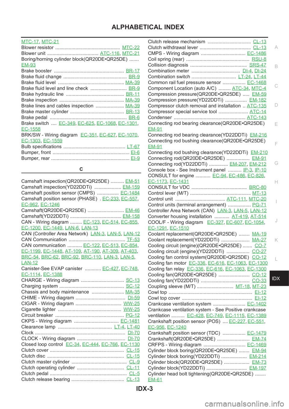
IDX-3
A
C
D
E
F
G
H
I
J
K
L B
IDX
ALPHABETICAL INDEX
MTC-17,MTC-21
Blower resistor ................................................ MTC-22
Blower unit ...................................... ATC-116,MTC-21
Boring/horning cylinder block(QR20DE•QR25DE) .......
EM-93
Brake booster .................................................... BR-17
Brake fluid change ............................................... BR-9
Brake fluid level ................................................. MA-39
Brake fluid level and line check ........................... BR-9
Brake hydraulic line ........................................... BR-11
Brake inspection ................................................ MA-39
Brake lines and cables inspection ..................... MA-39
Brake master cylinder ........................................ BR-13
Brake pedal ......................................................... BR-6
Brake switch .... EC-349,EC-625,EC-1068,EC-1301,
EC-1558
BRK/SW - Wiring diagram EC-351,EC-627,EC-1070,
EC-1303
,EC-1559
Bulb specifications .............................................. LT-67
Bumper, front ......................................................... EI-6
Bumper, rear .......................................................... EI-9
C
Camshaft inspection(QR20DE•QR25DE) .......... EM-51
Camshaft inspection(YD22DDTi) .................... EM-159
Camshaft position sensor (CMPS) ................ EC-1484
Camshaft position sensor (PHASE) . EC-233,EC-557,
EC-962
,EC-1246
Camshaft(QR20DE•QR25DE) ........................... EM-46
Camshaft(YD22DDTi) ...................................... EM-158
CAN - Wiring diagram ......... EC-123,EC-514,EC-855,
EC-1200
,EC-1449,LAN-6,LAN-13
CAN (Controller Area Network) LAN-3,LAN-5,LAN-12
CAN Communication .......................................... TF-53
CAN communication ........... EC-122,EC-513,EC-854,
EC-1199
,EC-1448,AT-109,AT-190,AT-309,AT-403,
BRC-54
,BRC-62,BRC-92,BRC-110,LAN-3,LAN-5,
LAN-12
Canister-See EVAP canister ............ EC-427,EC-748,
EC-1114
,EC-1388
CHARGE - Wiring diagram ................................ SC-13
Charging system ................................................ SC-12
Chassis and body maintenance ........................ MA-35
CHIME - Wiring diagram ..................................... DI-59
CIGAR - Wiring diagram .................................. WW-25
Cigarette lighter ............................................... WW-25
Circuit breaker ................................................... PG-12
CKPS - Wiring diagram ................................. EC-1481
Clearance lamp ........................................ LT-4,LT-40
Clock ................................................................... DI-70
CLOCK - Wiring diagram .................................... DI-70
Closed loop control EC-34,EC-444,EC-766,EC-1130
Clutch cover ....................................................... CL-15
Clutch disc ......................................................... CL-15
Clutch master cylinder ......................................... CL-9
Clutch operating cylinder ................................... CL-11
Clutch pedal ......................................................... CL-5
Clutch release bearing ....................................... CL-13
Clutch release mechanism ................................ CL-13
Clutch withdrawal lever ...................................... CL-13
CMPS - Wiring diagram ................................. EC-1486
Coil spring (rear) ............................................... RSU-8
Collision diagnosis .......................................... SRS-47
Combination meter .................................... DI-4,DI-24
Combination switch ................................. LT-24,LT-44
Common rail fuel pressure sensor ................. EC-1468
Component Location (auto A/C) ......... ATC-34,MTC-4
Compression pressure(QR20DE•QR25DE) ..... EM-59
Compression pressure(YD22DDTi) ................ EM-182
Compressor clutch removal and installation .. ATC-135
Compressor special service tool ...................... ATC-14
Condenser ..................................................... ATC-143
Connecting rod bearing clearance(QR20DE•QR25DE)
EM-91
Connecting rod bearing clearance(YD22DDTi) EM-216
Connecting rod bushing clearance(QR20DE•QR25DE)
EM-91
Connecting rod bushing clearance(YD22DDTi) EM-210
Connecting rod(QR20DE•QR25DE) ................. EM-91
Connecting rod(YD22DDTi) .............. EM-207,EM-212
Console box - See Instrument panel .......... IP-3,IP-10
CONSULT for engine ........... EC-94,EC-486,EC-826,
EC-1173
,EC-1431
CONSULT for VDC ......................................... BRC-80
Control lever (M/T) ............................................. MT-13
Control unit ..................................... ATC-111,MTC-20
Control units (terminal arrangement) ................. PG-71
Controller Area Network (CAN) LAN-3,LAN-5,LAN-12
Converter housing installation ........... AT-419,AT-514
COOL/F - Wiring diagram EC-327,EC-607,EC-1054,
EC-1291
,EC-1510
Coolant replacement(QR20DE•QR25DE) ........ MA-19
Coolant replacement(YD22DDTi) ..................... MA-27
Cooling circuit (engine)(QR20DE•QR25DE) ....... CO-7
Cooling circuit (engine)(YD22DDTi) ................. CO-27
Cooling fan control system(QR20DE•QR25DE) CO-12
Cooling fan motor EC-336,EC-616,EC-1063,EC-1300
Cooling fan relay EC-336,EC-616,EC-1063,EC-1300
Cooling fan(QR20DE•QR25DE) ....................... CO-12
Cooling fan(YD22DDTi) .................................... CO-33
Coupling sleeve (M/T) ........................... MT-18,MT-23
Cowl top .............................................................. EI-12
Cowl top cover .................................................... EI-12
Crankcase ventilation system ........................ EC-1402
Crankcase ventilation system - See Positive crankcase
ventilation .......... EC-428
,EC-749,EC-1115,EC-1389
Crankshaft position sensor (POS) .... EC-227,EC-551,
EC-956
,EC-1240
Crankshaft position sensor (TDC) ................. EC-1479
Crankshaft(QR20DE•QR25DE) ........................ EM-74
CRFPS - Wiring diagram ............................... EC-1469
Cylinder block boring(QR20DE•QR25DE) ........ EM-94
Cylinder block boring(YD22DDTi) ................... EM-214
Cylinder block(QR20DE•QR25DE) ................... EM-73
Cylinder block(YD22DDTi) .............................. EM-197
Cylinder head bolt tightening(QR20DE•QR25DE) ........
EM-61
Page 3829 of 3833

IDX-5
A
C
D
E
F
G
H
I
J
K
L B
IDX
ALPHABETICAL INDEX
EC-1368
Fan control amp. ............................. ATC-74,ATC-120
Fan switch ........................................ ATC-30,MTC-17
FIAR - Wiring diagram ................................... EC-1526
Final drive (FF M/T) .............................. MT-21,MT-26
Final drive disassembly ................................... RFD-11
Final drive removal and installation ................. RFD-11
Finisher, interior - See Trim ...................... EI-23,EI-25
Finisher, rear panel .............................................. EI-22
Floor trim ............................................................. EI-28
Flow charts ......................................................... GI-23
Fluid temperature sensor (A/T) ........................ AT-121
Fluorescent leak detector .............................. ATC-147
Flywheel (clutch) ................................................ CL-15
Flywheel runout(QR20DE•QR25DE) ................. EM-97
Flywheel runout(YD22DDTi) ............................ EM-218
Fog lamp, front ................................................... LT-33
Fork rod (M/T) ....................................... MT-20,MT-25
Freeze frame data EC-48,EC-455,EC-780,EC-1142
FRO2 - Wiring diagram .................... EC-672,EC-1321
FRO2/H - Wiring diagram ................ EC-658,EC-1308
Front bumper ......................................................... EI-6
Front disc brake ................................................. BR-21
Front door ............................................................. BL-8
Front Door Trim ................................................... EI-23
Front fog lamp .................................................... LT-33
Front passenger air bag .................................. SRS-35
Front seat ............................................................ SE-7
Front seat belt ...................................................... SB-3
Front seat belt pre-tensioner .... SB-2,SRS-3,SRS-39
Front side air bag ............................................. SRS-36
Front suspension ............................................... FSU-5
Front washer ...................................................... WW-4
Front wiper ......................................................... WW-4
FTS - Wiring diagram .................................... EC-1497
Fuel check valve ................ EC-425,EC-746,EC-1112
Fuel cut control (at no load high engine speed) EC-37,
EC-447
,EC-769,EC-1133,EC-1401
Fuel filler lid ........................................................ BL-75
Fuel filter ........................................................ EC-1404
Fuel filter replacement(QR20DE•QR25DE) .......... FL-4
Fuel filter replacement(YD22DDTi) ....... FL-15,MA-31
Fuel gauge .................................................. DI-4,DI-24
Fuel injection control system ......................... EC-1399
Fuel injection system .......... EC-200,EC-206,EC-934,
EC-940
Fuel injector ................................................... EC-1472
Fuel injector adjustment resistor .................... EC-1525
Fuel injector and fuel tube(QR20DE•QR25DE) . EM-32
Fuel injector and fuel tube(YD22DDTi) ............ EM-144
Fuel leak ........................................................ EC-1529
Fuel line inspection(QR20DE•QR25DE) . FL-3,MA-22
Fuel line inspection(YD22DDTi) ............ FL-14,MA-30
Fuel pressure check EC-42,EC-452,EC-775,EC-1139
Fuel pressure release ........... EC-42,EC-452,EC-775,
EC-1139
Fuel pressure relief valve .............................. EC-1405
Fuel pump ......... EC-405,EC-726,EC-1092,EC-1366
Fuel pump and gauge(QR20DE•QR25DE) .......... FL-4
Fuel system(QR20DE•QR25DE) .......................... FL-3
Fuel system(YD22DDTi) ..................................... FL-14
Fuel tank(QR20DE•QR25DE) ............................... FL-9
Fuel tank(YD22DDTi) ......................................... FL-21
Fuel temperature sensor ................................ EC-1496
Fuse ................................................................... PG-12
Fuse and fusible link box ................................... PG-75
Fusible link ......................................................... PG-12
G
Gear components (M/T) ........................ MT-18
,MT-23
Generator ........................................................... SC-12
Generator - See Alternator ................................ SC-12
Generic scan tool (GST) .................... EC-104,EC-836
Glass ................................................... GW-44,GW-46
GLOW - Wiring diagram ................................ EC-1545
Glow plug ....................................................... EC-1544
Glow plug(YD22DDTi) .................................... EM-138
Glow relay ...................................................... EC-1544
Grille - See Exterior ............................................ EI-11
Ground distribution ............................................ PG-13
G-sensor ............................................................ TF-50
H
H/AIM - Wiring diagram ...................................... LT-15
H/LAMP - Wiring diagram ........................... LT-4,LT-5
H/MIRROR - Wiring diagram ............................ GW-15
Harness connector ............................................. PG-68
Harness layout ................................................... PG-29
Headlamp ............................................................. LT-4
Headlamp aiming control .................................... LT-15
Headlamp leveler - See Headlamp aiming control .......
LT-15
Headlamp washer ............................................ WW-19
Headlining - See Roof trim .................................. EI-29
Heated oxygen sensor 1 .... EC-163,EC-169,EC-178,
EC-295
,EC-301,EC-534,EC-671,EC-899,EC-905,
EC-914
,EC-1023,EC-1029,EC-1229,EC-1320
Heated oxygen sensor 1 heater ........ EC-128,EC-657,
EC-860
,EC-1307
Heated oxygen sensor 2 .... EC-185,EC-192,EC-307,
EC-315
,EC-677,EC-921,EC-927,EC-1035,EC-1042,
EC-1326
Heated oxygen sensor 2 heater ........ EC-133,EC-662,
EC-865
,EC-1312
Heated seat ............................................... SE-3,SE-5
HEATER - Wiring diagram ................................ MTC-6
Heater and cooling unit (Heater core) ............ ATC-122
Heater mirror ..................................................... GW-15
Heater system - Wiring diagram ....................... MTC-6
Heater unit (heater core) .. ATC-126,MTC-24,MTC-26
HFC134a (R134a) system precaution ............... ATC-4
HFC134a (R134a) system service procedure ATC-129
HFC134a (R134a) system service tools .......... ATC-15
HFC134a system service equipment precaution ..........
ATC-10
HO2S1 - Wiring diaram ...... EC-130,EC-165,EC-172,