Injectors NISSAN X-TRAIL 2001 Service Repair Manual
[x] Cancel search | Manufacturer: NISSAN, Model Year: 2001, Model line: X-TRAIL, Model: NISSAN X-TRAIL 2001Pages: 3833, PDF Size: 39.49 MB
Page 8 of 3833
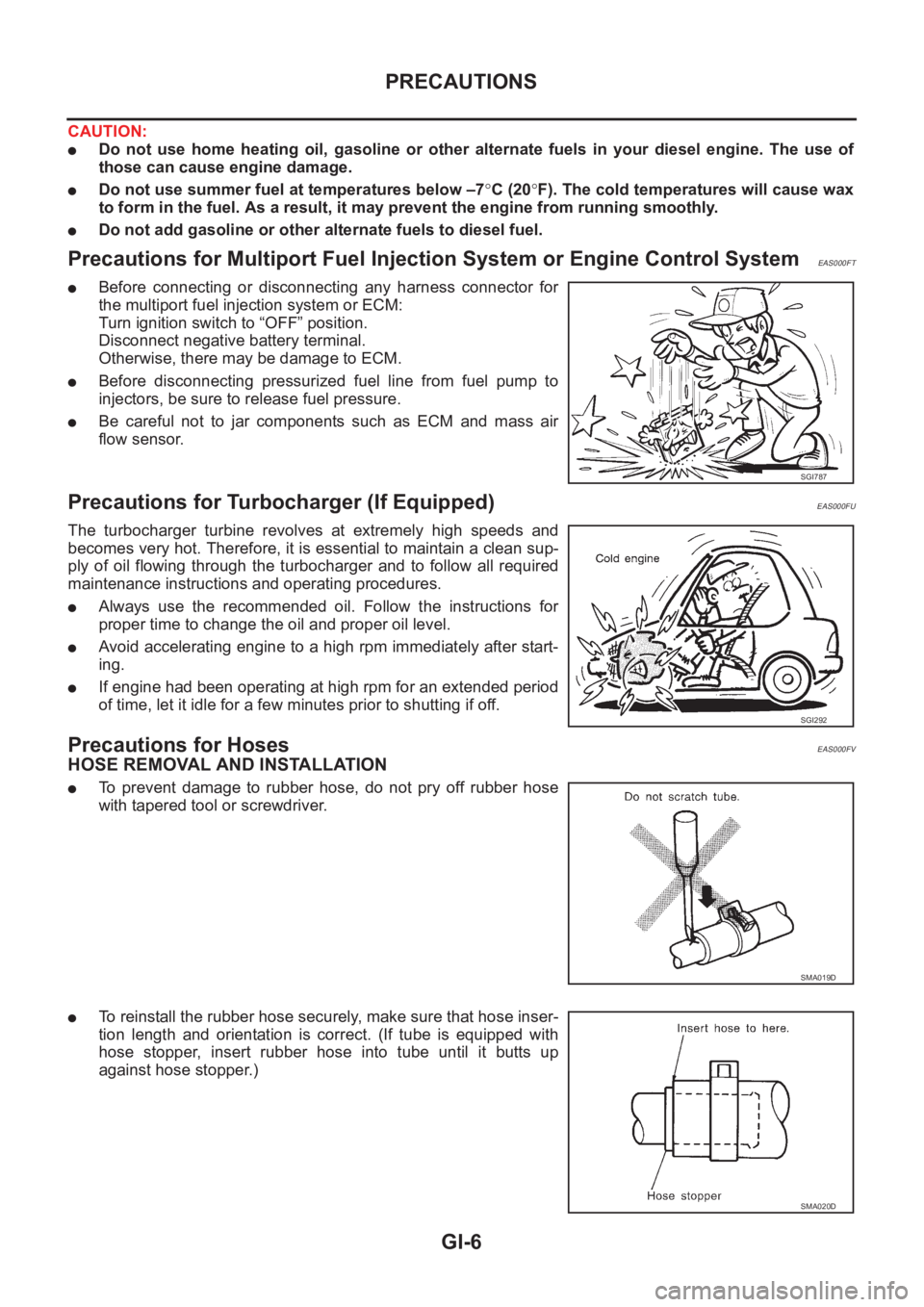
GI-6
PRECAUTIONS
CAUTION:
●Do not use home heating oil, gasoline or other alternate fuels in your diesel engine. The use of
those can cause engine damage.
●Do not use summer fuel at temperatures below –7°C (20°F). The cold temperatures will cause wax
to form in the fuel. As a result, it may prevent the engine from running smoothly.
●Do not add gasoline or other alternate fuels to diesel fuel.
Precautions for Multiport Fuel Injection System or Engine Control SystemEAS000FT
●Before connecting or disconnecting any harness connector for
the multiport fuel injection system or ECM:
Turn ignition switch to “OFF” position.
Disconnect negative battery terminal.
Otherwise, there may be damage to ECM.
●Before disconnecting pressurized fuel line from fuel pump to
injectors, be sure to release fuel pressure.
●Be careful not to jar components such as ECM and mass air
flow sensor.
Precautions for Turbocharger (If Equipped)EAS000FU
The turbocharger turbine revolves at extremely high speeds and
becomes very hot. Therefore, it is essential to maintain a clean sup-
ply of oil flowing through the turbocharger and to follow all required
maintenance instructions and operating procedures.
●Always use the recommended oil. Follow the instructions for
proper time to change the oil and proper oil level.
●Avoid accelerating engine to a high rpm immediately after start-
ing.
●If engine had been operating at high rpm for an extended period
of time, let it idle for a few minutes prior to shutting if off.
Precautions for HosesEAS000FV
HOSE REMOVAL AND INSTALLATION
●To prevent damage to rubber hose, do not pry off rubber hose
with tapered tool or screwdriver.
●To reinstall the rubber hose securely, make sure that hose inser-
tion length and orientation is correct. (If tube is equipped with
hose stopper, insert rubber hose into tube until it butts up
against hose stopper.)
SGI787
SGI292
SMA019D
SMA020D
Page 383 of 3833
![NISSAN X-TRAIL 2001 Service Repair Manual ENGINE CONTROL SYSTEM
EC-33
[QR25(WITH EURO-OBD)]
C
D
E
F
G
H
I
J
K
L
MA
EC
System ChartEBS00M0B
*1: This sensor is not used to control the engine system under normal conditions.
*2: These signals are](/img/5/57405/w960_57405-382.png "NISSAN X-TRAIL 2001 Service Repair Manual ENGINE CONTROL SYSTEM
EC-33
[QR25(WITH EURO-OBD)]
C
D
E
F
G
H
I
J
K
L
MA
EC
System ChartEBS00M0B
*1: This sensor is not used to control the engine system under normal conditions.
*2: These signals are")
ENGINE CONTROL SYSTEM
EC-33
[QR25(WITH EURO-OBD)]
C
D
E
F
G
H
I
J
K
L
MA
EC
System ChartEBS00M0B
*1: This sensor is not used to control the engine system under normal conditions.
*2: These signals are sent to the ECM through CAN communication line.
Multiport Fuel Injection (MFI) SystemEBS00M0C
INPUT/OUTPUT SIGNAL CHART
*1: Under normal conditions, this sensor is not for engine control operation.
SYSTEM DESCRIPTION
The amount of fuel injected from the fuel injector is determined by the ECM. The ECM controls the length of
time the valve remains open (injection pulse duration). The amount of fuel injected is a program value in the
ECM memory. The program value is preset by engine operating conditions. These conditions are determined
Input (Sensor) ECM Function Output (Actuator)
●Camshaft position sensor (PHASE)
●Crankshaft position sensor (POS)
●Mass air flow sensor
●Engine coolant temperature sensor
●Heated oxygen sensor 1
●Throttle position sensor
●Accelerator pedal position sensor
●Park/neutral position (PNP) switch
●Intake air temperature sensor
●Power steering pressure sensor
●Ignition switch
●Battery voltage
●Knock sensor
●Refrigerant pressure sensor
●Heated oxygen sensor 2 *1
●TCM (Transmission control module) *2
●Wheel sensor
●Air conditioner switch
●Electrical loadFuel injection & mixture ratio control Fuel injectors
Electronic ignition system Power transistors
Fuel pump control Fuel pump relay
On board diagnostic system MI (On the instrument panel)
Heated oxygen sensor 1 heater control Heated oxygen sensor 1 heater
Heated oxygen sensor 2 heater control Heated oxygen sensor 2 heater
Power valve control VIAS control solenoid valve
EVAP canister purge flow controlEVAP canister purge volume control
solenoid valve
Air conditioning cut control Air conditioner relay
Cooling fan control Cooling fan relays
Sensor Input Signal to ECMECM func-
tionActuator
Crankshaft position sensor (POS)
Engine speed
Piston position
Fuel injec-
tion & mix-
ture ratio
controlFuel injectors Camshaft position sensor (PHASE)
Mass air flow sensor Amount of intake air
Engine coolant temperature sensor Engine coolant temperature
Heated oxygen sensor 1 Density of oxygen in exhaust gas
Throttle position sensor Throttle position
Accelerator pedal position sensor Accelerator pedal position
Park/neutral position (PNP) switch Gear position
Ignition switch Start signal
Knock sensor Engine knocking condition
Battery Battery voltage
Power steering pressure sensor Power steering operation
Heated oxygen sensor 2 *
1Density of oxygen in exhaust gas
Wheel sensor Vehicle speed
Air conditioner switch Air conditioner operation
Page 385 of 3833
![NISSAN X-TRAIL 2001 Service Repair Manual ENGINE CONTROL SYSTEM
EC-35
[QR25(WITH EURO-OBD)]
C
D
E
F
G
H
I
J
K
L
MA
EC
inally designed. Both manufacturing differences (i.e., mass air flow sensor hot film) and characteristic changes
during oper](/img/5/57405/w960_57405-384.png "NISSAN X-TRAIL 2001 Service Repair Manual ENGINE CONTROL SYSTEM
EC-35
[QR25(WITH EURO-OBD)]
C
D
E
F
G
H
I
J
K
L
MA
EC
inally designed. Both manufacturing differences (i.e., mass air flow sensor hot film) and characteristic changes
during oper")
ENGINE CONTROL SYSTEM
EC-35
[QR25(WITH EURO-OBD)]
C
D
E
F
G
H
I
J
K
L
MA
EC
inally designed. Both manufacturing differences (i.e., mass air flow sensor hot film) and characteristic changes
during operation (i.e., injector clogging) directly affect mixture ratio.
Accordingly, the difference between the basic and theoretical mixture ratios is monitored in this system. This is
then computed in terms of “injection pulse duration” to automatically compensate for the difference between
the two ratios.
“Fuel trim” refers to the feedback compensation value compared against the basic injection duration. Fuel trim
includes short term fuel trim and long term fuel trim.
“Short term fuel trim” is the short-term fuel compensation used to maintain the mixture ratio at its theoretical
value. The signal from heated oxygen sensor 1 indicates whether the mixture ratio is RICH or LEAN compared
to the theoretical value. The signal then triggers a reduction in fuel volume if the mixture ratio is rich, and an
increase in fuel volume if it is lean.
“Long term fuel trim” is overall fuel compensation carried out long-term to compensate for continual deviation
of the short term fuel trim from the central value. Such deviation will occur due to individual engine differences,
wear over time and changes in the usage environment.
FUEL INJECTION TIMING
Two types of systems are used.
Sequential Multiport Fuel Injection System
Fuel is injected into each cylinder during each engine cycle according to the firing order. This system is used
when the engine is running.
Simultaneous Multiport Fuel Injection System
Fuel is injected simultaneously into all four cylinders twice each engine cycle. In other words, pulse signals of
the same width are simultaneously transmitted from the ECM.
The four injectors will then receive the signals two times for each engine cycle.
This system is used when the engine is being started and/or if the fail-safe system (CPU) is operating.
FUEL SHUT-OFF
Fuel to each cylinder is cut off during deceleration or operation of the engine at excessively high speeds.
Electronic Ignition (EI) SystemEBS00M0D
INPUT/OUTPUT SIGNAL CHART
SEF337W
Sensor Input Signal to ECMECM func-
tionActuator
Crankshaft position sensor (POS)
Engine speed
Piston position
Ignition
timing con-
trolPower transistor Camshaft position sensor (PHASE)
Mass air flow sensor Amount of intake air
Engine coolant temperature sensor Engine coolant temperature
Throttle position sensor Throttle position
Accelerator pedal position sensor Accelerator pedal position
Ignition switch Start signal
Knock sensor Engine knocking
Park/neutral position (PNP) switch Gear position
Battery Battery voltage
Wheel sensor Vehicle speed
Page 387 of 3833
![NISSAN X-TRAIL 2001 Service Repair Manual ENGINE CONTROL SYSTEM
EC-37
[QR25(WITH EURO-OBD)]
C
D
E
F
G
H
I
J
K
L
MA
EC
Fuel Cut Control (at No Load and High Engine Speed)EBS00M0F
INPUT/OUTPUT SIGNAL CHART
SYSTEM DESCRIPTION
If the engine sp](/img/5/57405/w960_57405-386.png "NISSAN X-TRAIL 2001 Service Repair Manual ENGINE CONTROL SYSTEM
EC-37
[QR25(WITH EURO-OBD)]
C
D
E
F
G
H
I
J
K
L
MA
EC
Fuel Cut Control (at No Load and High Engine Speed)EBS00M0F
INPUT/OUTPUT SIGNAL CHART
SYSTEM DESCRIPTION
If the engine sp")
ENGINE CONTROL SYSTEM
EC-37
[QR25(WITH EURO-OBD)]
C
D
E
F
G
H
I
J
K
L
MA
EC
Fuel Cut Control (at No Load and High Engine Speed)EBS00M0F
INPUT/OUTPUT SIGNAL CHART
SYSTEM DESCRIPTION
If the engine speed is above 1,800 rpm with no load (for example, in neutral and engine speed over 1,800
rpm) fuel will be cut off after some time. The exact time when the fuel is cut off varies based on engine speed.
Fuel cut will operate until the engine speed reaches 1,500 rpm, then fuel cut is cancelled.
NOTE:
This function is different from deceleration control listed under “Multiport Fuel Injection (MFI) System”, EC-33
.
CAN CommunicationEBS00NBI
SYSTEM DESCRIPTION
CAN (Controller Area Network) is a serial communication line for real time application. It is an on-vehicle mul-
tiplex communication line with high data communication speed and excellent error detection ability. Many elec-
tronic control units are equipped onto a vehicle, and each control unit shares information and links with other
control units during operation (not independent). In CAN communication, control units are connected with 2
communication lines (CAN H line, CAN L line) allowing a high rate of information transmission with less wiring.
Each control unit transmits/receives data but selectively reads required data only.
FOR A/T MODELS
System diagram
Input/output signal chart
T: Transmit R: Receive Sensor Input Signal to ECMECM func-
tionActuator
Park/neutral position (PNP) switch Neutral position
Fuel cut
controlFuel injectors Throttle position sensor Throttle position
Accelerator pedal position sensor Accelerator pedal position
Engine coolant temperature sensor Engine coolant temperature
Crankshaft position sensor (POS) Engine speed
Wheel sensor Vehicle speed
SKIA0884E
Signals ECM TCM
Engine coolant temperature signal T R
Accelerator pedal position signal T R
A/T self-diagnosis signal R T
Page 446 of 3833
![NISSAN X-TRAIL 2001 Service Repair Manual EC-96
[QR25(WITH EURO-OBD)]
TROUBLE DIAGNOSIS
X: Applicable
*1: This item includes 1st trip DTCs.
*2: This mode includes 1st trip freeze frame data or freeze frame data. The items appear on CONSULT-I](/img/5/57405/w960_57405-445.png "NISSAN X-TRAIL 2001 Service Repair Manual EC-96
[QR25(WITH EURO-OBD)]
TROUBLE DIAGNOSIS
X: Applicable
*1: This item includes 1st trip DTCs.
*2: This mode includes 1st trip freeze frame data or freeze frame data. The items appear on CONSULT-I")
EC-96
[QR25(WITH EURO-OBD)]
TROUBLE DIAGNOSIS
X: Applicable
*1: This item includes 1st trip DTCs.
*2: This mode includes 1st trip freeze frame data or freeze frame data. The items appear on CONSULT-II screen in freeze frame data
mode only if a 1st trip DTC or DTC is detected. For details, refer to EC-48
.
CONSULT-II INSPECTION PROCEDURE
1. Turn ignition switch OFF.
2. Connect “CONSULT-II” to data link connector, which is located
under LH dash panel near the fuse box cover.
3. Turn ignition switch ON.
4. Touch “START (NISSAN BASED VHCL)”.
5. Touch “ENGINE”.
ENGINE CONTROL COMPONENT PARTS
OUTPUT
Injectors×× ×
Power transistor (Ignition timing)×× ×
Throttle control motor relay×××
EVAP canister purge volume con-
trol solenoid valve××××
Air conditioner relay××
Fuel pump relay××××
Cooling fan relay××××
Heated oxygen sensor 1 heater××××
Heated oxygen sensor 2 heater××××
Intake valve timing control solenoid
valve××××
Calculated load value×××
VIAS control solenoid valve×× × ItemDIAGNOSTIC TEST MODE
WORK
SUP-
PORTSELF-DIAGNOSTIC
RESULTS
DATA
MONI-
TORDATA
MONI-
TOR
(SPEC)ACTIVE
TESTDTC & SRT
CONFIRMATION
DTC*1FREEZE
FRAME
DATA*2SRT
STATUSDTC
WORK
SUP-
PORT
PBIB0376E
MBIB0233E
Page 452 of 3833
![NISSAN X-TRAIL 2001 Service Repair Manual EC-102
[QR25(WITH EURO-OBD)]
TROUBLE DIAGNOSIS
DATA MONITOR (SPEC) MODE
Monitored Item
NOTE:
●Any monitored item that does not match the vehicle being diagnosed is deleted from the display automatic](/img/5/57405/w960_57405-451.png "NISSAN X-TRAIL 2001 Service Repair Manual EC-102
[QR25(WITH EURO-OBD)]
TROUBLE DIAGNOSIS
DATA MONITOR (SPEC) MODE
Monitored Item
NOTE:
●Any monitored item that does not match the vehicle being diagnosed is deleted from the display automatic")
EC-102
[QR25(WITH EURO-OBD)]
TROUBLE DIAGNOSIS
DATA MONITOR (SPEC) MODE
Monitored Item
NOTE:
●Any monitored item that does not match the vehicle being diagnosed is deleted from the display automatically.
ACTIVE TEST MODE
Test Item
Monitored item [Unit]ECM
input
signalsMain
signalsDescription Remarks
ENG SPEED [rpm]×
●Indicates the engine speed computed
from the signals of the crankshaft posi-
tion sensor (POS) and camshaft position
sensor (PHASE).
MAS A/F SE-B1 [V]××
●The signal voltage of the mass air flow
sensor specification is displayed.●When engine is running specification
range is indicated.
B/FUEL SCHDL
[msec]
●“Base fuel schedule” indicates the fuel
injection pulse width programmed into
ECM, prior to any learned on board cor-
rection.
●When engine is running specification
range is indicated.
A/F ALPHA-B1 [%]×
●The mean value of the air-fuel ratio feed-
back correction factor per cycle is indi-
cated.●When engine is running specification
range is indicated.
●This data also includes the data for the
air-fuel ratio learning control.
TEST ITEM CONDITION JUDGEMENT CHECK ITEM (REMEDY)
FUEL INJEC-
TION
●Engine: Return to the original
trouble condition
●Change the amount of fuel injec-
tion using CONSULT-II.If trouble symptom disappears, see
CHECK ITEM.
●Harness and connectors
●Fuel injectors
●Heated oxygen sensor 1
IGNITION TIM-
ING
●Engine: Return to the original
trouble condition
●Timing light: Set
●Retard the ignition timing using
CONSULT-II.If trouble symptom disappears, see
CHECK ITEM.
●Perform “Idle Air Volume Learn-
ing”.
POWER BAL-
ANCE
●Engine: After warming up, idle
the engine.
●A/C switch “OFF”
●Shift lever “N”
●Cut off each injector signal one at
a time using CONSULT-II.Engine runs rough or dies.
●Harness and connectors
●Compression
●Fuel injectors
●Power transistor
●Spark plugs
●Ignition coils
COOLING FAN
●Ignition switch: ON
●Turn the cooling fan “ON” and
“OFF” with CONSULT-II.Cooling fan moves and stops.
●Harness and connectors
●Cooling fan relay
●Cooling fan motor
ENG COOLANT
TEMP
●Engine: Return to the original
trouble condition
●Change the engine coolant tem-
perature using CONSULT-II.If trouble symptom disappears, see
CHECK ITEM.
●Harness and connectors
●Engine coolant temperature sen-
sor
●Fuel injectors
FUEL PUMP
RELAY
●Ignition switch: ON (Engine
stopped)
●Turn the fuel pump relay “ON”
and “OFF” using CONSULT-II
and listen to operating sound.Fuel pump relay makes the operat-
ing sound.●Harness and connectors
●Fuel pump relay
Page 520 of 3833
![NISSAN X-TRAIL 2001 Service Repair Manual EC-170
[QR25(WITH EURO-OBD)]
DTC P0133 HO2S1
On Board Diagnosis Logic
EBS00M3L
To judge the malfunction of heated oxygen sensor 1, this diagnosis
measures response time of heated oxygen sens](/img/5/57405/w960_57405-519.png "NISSAN X-TRAIL 2001 Service Repair Manual EC-170
[QR25(WITH EURO-OBD)]
DTC P0133 HO2S1
On Board Diagnosis Logic
EBS00M3L
To judge the malfunction of heated oxygen sensor 1, this diagnosis
measures response time of heated oxygen sens")
EC-170
[QR25(WITH EURO-OBD)]
DTC P0133 HO2S1
On Board Diagnosis Logic
EBS00M3L
To judge the malfunction of heated oxygen sensor 1, this diagnosis
measures response time of heated oxygen sensor 1 signal. The time
is compensated by engine operating (speed and load), fuel feedback
control constant, and heated oxygen sensor 1 temperature index.
Judgment is based on whether the compensated time (heated oxy-
gen sensor 1 cycling time index) is inordinately long or not.
DTC Confirmation ProcedureEBS00M3M
CAUTION:
Always drive vehicle at a safe speed.
NOTE:
If “DTC Confirmation Procedure” has been previously conducted, always turn ignition switch “OFF” and wait at
least 10 seconds before conducting the next test.
TESTING CONDITION:
●Always perform at a temperature above −10°C (14°F).
●Before performing the following procedure, confirm that battery voltage is more than 11V at idle.
WITH CONSULT-II
1. Start engine and warm it up to normal operating temperature.
2. Stop engine and wait at least 10 seconds.
3. Turn ignition switch “ON” and select “HO2S1 (B1) P0133” of “HO2S1” in “DTC WORK SUPPORT” mode
with CONSULT-II.
4. Touch “START”.
5. Start engine and let it idle for at least 3 minutes.
NOTE:
Never raise engine speed above 3,600 rpm after this step. If
the engine speed limit is exceeded, return to step 5.
SEF010V
DTC No. Trouble diagnosis name DTC detecting condition Possible cause
P0133
0133Heated oxygen sensor
1 circuit slow responseThe response of the voltage signal from the
sensor takes more than the specified time.
●Harness or connectors
(The sensor circuit is open or shorted)
●Heated oxygen sensor 1
●Heated oxygen sensor 1 heater
●Fuel pressure
●Injectors
●Intake air leaks
●Exhaust gas leaks
●PCV valve
●Mass air flow sensor
SEF338Z
Page 543 of 3833
![NISSAN X-TRAIL 2001 Service Repair Manual DTC P0139 HO2S2
EC-193
[QR25(WITH EURO-OBD)]
C
D
E
F
G
H
I
J
K
L
MA
EC
DTC Confirmation ProcedureEBS00M4G
NOTE:
If “DTC Confirmation Procedure” has been previously conducted, always turn ignition](/img/5/57405/w960_57405-542.png "NISSAN X-TRAIL 2001 Service Repair Manual DTC P0139 HO2S2
EC-193
[QR25(WITH EURO-OBD)]
C
D
E
F
G
H
I
J
K
L
MA
EC
DTC Confirmation ProcedureEBS00M4G
NOTE:
If “DTC Confirmation Procedure” has been previously conducted, always turn ignition")
DTC P0139 HO2S2
EC-193
[QR25(WITH EURO-OBD)]
C
D
E
F
G
H
I
J
K
L
MA
EC
DTC Confirmation ProcedureEBS00M4G
NOTE:
If “DTC Confirmation Procedure” has been previously conducted, always turn ignition switch “OFF” and wait at
least 10 seconds before conducting the next test.
TESTING CONDITION:
For the best results, perform “DTC WORK SUPPORT” at a temperature of 0 to 30°C (32 to 86°F).
Open engine hood before conducting following procedure.
WITH CONSULT-II
1. Start engine and warm it up to normal operating temperature.
2. Turn ignition switch “OFF” and wait at least 10 seconds.
3. Start engine and keep the engine speed between 3,500 and 4,000 rpm for at lest one minute under no
load.
4. Let engine idle for one minute.
5. Select “HO2S2 (B1) P0139” of “HO2S2” in “DTC WORK SUPPORT” mode with CONSULT-II and follow
the instruction of CONSULT-II.
6. Make sure that “OK” is displayed after touching “SELF-DIAG RESULTS”.
If “NG” is displayed, refer to EC-196, "
Diagnostic Procedure" .
If “CAN NOT BE DIAGNOSED” is displayed, perform the following.
a. Turn ignition switch “OFF” and leave the vehicle in a cool place (soak the vehicle).
b. Turn ignition switch “ON” and select “COOLANTEMP/S” in “DATA MONITOR” mode with CONSULT-II.
c. Start engine and warm it up while monitoring “COOLANTEMP/S” indication on CONSULT-II.
d. When “COOLANTEMP/S” indication reaches to 70°C (158°F), go to step 3.
Overall Function CheckEBS00M4H
Use this procedure to check the overall function of the heated oxygen sensor 2 circuit. During this check, a
DTC might not be confirmed.
CAUTION:
Always drive vehicle at a safe speed.
WITH GST
1. Start engine and warm it up to the normal operating temperature.
2. Turn ignition switch “OFF” and wait at least 10 seconds.
3. Start engine and keep the engine speed between 3,500 and 4,000 rpm for at least one minute under no
load.
4. Let engine idle for one minute.
DTC No. Trouble diagnosis name DTC detecting condition Possible cause
P0139
0139Heated oxygen sensor
2 circuit slow responseIt takes more time for the sensor to respond
between rich and lean than the specified time.
●Harness or connectors
(The sensor circuit is open or shorted)
●Heated oxygen sensor 2
●Fuel pressure
●Injectors
●Intake air leaks
PBIB0115E
Page 550 of 3833
![NISSAN X-TRAIL 2001 Service Repair Manual EC-200
[QR25(WITH EURO-OBD)]
DTC P0171 FUEL INJECTION SYSTEM FUNCTION
DTC P0171 FUEL INJECTION SYSTEM FUNCTION
PFP:16600
On Board Diagnosis LogicEBS00M4M
With the Air-Fuel Mixture Ratio Self-Lear](/img/5/57405/w960_57405-549.png "NISSAN X-TRAIL 2001 Service Repair Manual EC-200
[QR25(WITH EURO-OBD)]
DTC P0171 FUEL INJECTION SYSTEM FUNCTION
DTC P0171 FUEL INJECTION SYSTEM FUNCTION
PFP:16600
On Board Diagnosis LogicEBS00M4M
With the Air-Fuel Mixture Ratio Self-Lear")
EC-200
[QR25(WITH EURO-OBD)]
DTC P0171 FUEL INJECTION SYSTEM FUNCTION
DTC P0171 FUEL INJECTION SYSTEM FUNCTION
PFP:16600
On Board Diagnosis LogicEBS00M4M
With the Air-Fuel Mixture Ratio Self-Learning Control, the actual mixture ratio can be brought closely to the
theoretical mixture ratio based on the mixture ratio feedback signal from the heated oxygen sensor 1. The
ECM calculates the necessary compensation to correct the offset between the actual and the theoretical
ratios.
In case the amount of the compensation value is extremely large (The actual mixture ratio is too lean.), the
ECM judges the condition as the fuel injection system malfunction and light up the MI (2 trip detection logic).
DTC Confirmation ProcedureEBS00M4N
NOTE:
If “DTC Confirmation Procedure” has been previously conducted, always turn ignition switch “OFF” and wait at
least 10 seconds before conducting the next test.
WITH CONSULT-II
1. Start engine and warm it up to normal operating temperature.
2. Turn ignition switch “OFF” and wait at least 10 seconds.
3. Turn ignition switch “ON” and select “SELF-LEARNING CONT” in “WORK SUPPORT” mode with CON-
SULT-II.
4. Clear the self-learning control coefficient by touching “CLEAR”.
5. Select “DATA MONITOR” mode with CONSULT-II.
6. Start engine again and let it idle for at least 10 minutes.
The 1st trip DTC P0171 should be detected at this stage, if a
malfunction exists. If so, go to EC-203, "
Diagnostic Procedure" .
7. If it is difficult to start engine at step 6, the fuel injection system
has a malfunction, too.
8. Crank engine while depressing accelerator pedal. If engine
starts, go to EC-203, "
Diagnostic Procedure" . If engine does not
start, check exhaust and intake air leak visually.
WITH GST
1. Start engine and warm it up to normal operating temperature.
2. Turn ignition switch “OFF” and wait at least 10 seconds.
Sensor Input Signal to ECMECM
functionActuator
Heated oxygen sensors 1Density of oxygen in exhaust gas
(Mixture ratio feedback signal)Fuel injec-
tion controlFuel injectors
DTC No.Trouble diagnosis
nameDTC detecting condition Possible cause
P0171
0171Fuel injection system
too lean
●Fuel injection system does not operate properly.
●The amount of mixture ratio compensation is too
large.
(The mixture ratio is too lean.)
●Intake air leaks
●Heated oxygen sensor 1
●Injectors
●Exhaust gas leaks
●Incorrect fuel pressure
●Lack of fuel
●Mass air flow sensor
●Incorrect PCV hose connection
SEF215Z
Page 554 of 3833
![NISSAN X-TRAIL 2001 Service Repair Manual EC-204
[QR25(WITH EURO-OBD)]
DTC P0171 FUEL INJECTION SYSTEM FUNCTION
5. CHECK MASS AIR FLOW SENSOR
With CONSULT-II
1. Install all removed parts.
2. Check “MASS AIR FLOW” in “DATA MONITOR” mod](/img/5/57405/w960_57405-553.png "NISSAN X-TRAIL 2001 Service Repair Manual EC-204
[QR25(WITH EURO-OBD)]
DTC P0171 FUEL INJECTION SYSTEM FUNCTION
5. CHECK MASS AIR FLOW SENSOR
With CONSULT-II
1. Install all removed parts.
2. Check “MASS AIR FLOW” in “DATA MONITOR” mod")
EC-204
[QR25(WITH EURO-OBD)]
DTC P0171 FUEL INJECTION SYSTEM FUNCTION
5. CHECK MASS AIR FLOW SENSOR
With CONSULT-II
1. Install all removed parts.
2. Check “MASS AIR FLOW” in “DATA MONITOR” mode with CONSULT-II.
With GST
1. Install all removed parts.
2. Check mass air flow sensor signal in MODE 1 with GST.
OK or NG
OK >> GO TO 6.
NG >> Check connectors for rusted terminals or loose connections in the mass air flow sensor circuit or
engine grounds. Refer to EC-138, "
DTC P0102, P0103 MAF SENSOR" .
6. CHECK FUNCTION OF INJECTORS
With CONSULT-II
1. Start engine.
2. Perform “POWER BALANCE” in “ACTIVE TEST” mode with
CONSULT-II.
3. Make sure that each circuit produces a momentary engine
speed drop.
Without CONSULT-II
1. Start engine.
2. Listen to each injector operating sound.
OK or NG
OK >> GO TO 7.
NG >> Perform trouble diagnosis for “INJECTORS”, EC-388
. 1.0 - 4.0 g·m/sec: at idling
4.0 - 10 g·m/sec: at 2,500 rpm
1.0 - 4.0 g·m/sec: at idling
4.0 - 10 g·m/sec: at 2,500 rpm
PBIB0133E
Clicking noise should be heard.
MEC703B