hood release NISSAN X-TRAIL 2001 Service Repair Manual
[x] Cancel search | Manufacturer: NISSAN, Model Year: 2001, Model line: X-TRAIL, Model: NISSAN X-TRAIL 2001Pages: 3833, PDF Size: 39.49 MB
Page 20 of 3833

GI-18
HOW TO USE THIS MANUAL
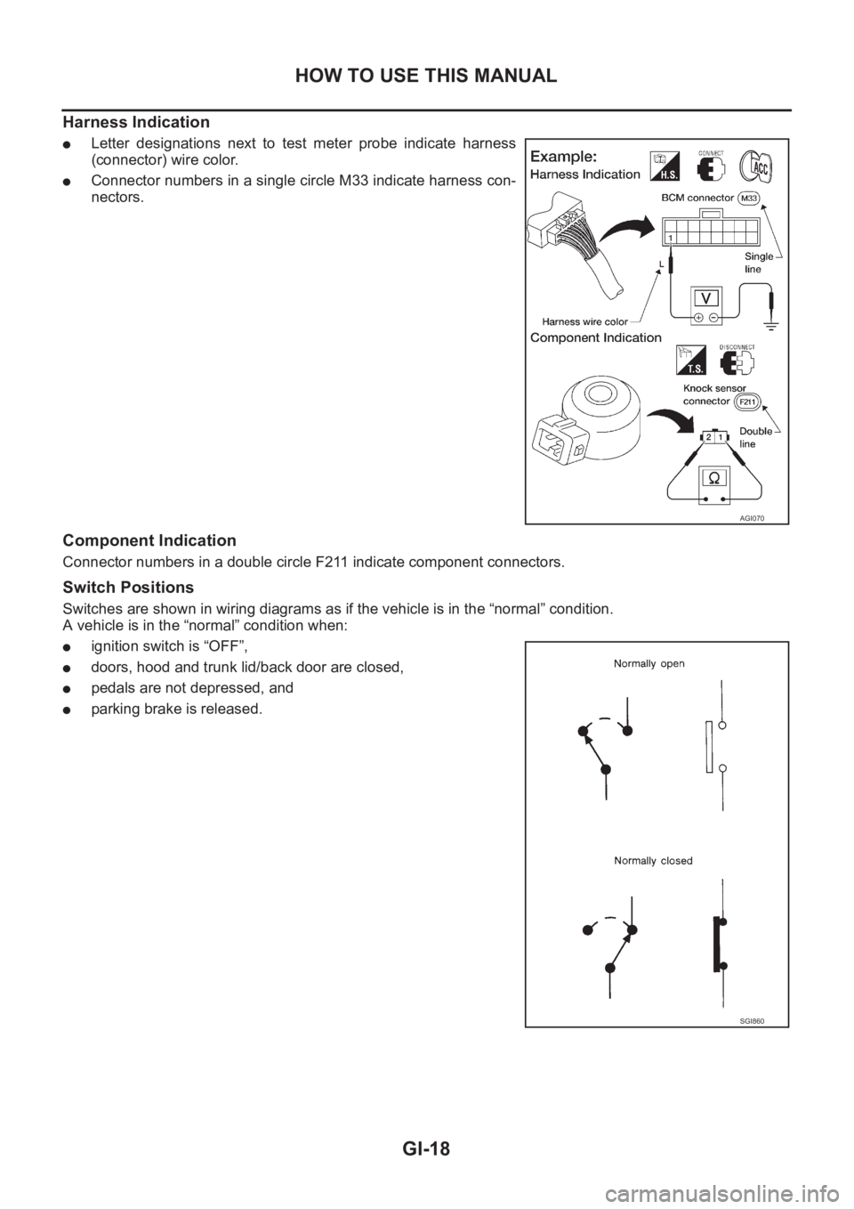
Harness Indication
●Letter designations next to test meter probe indicate harness
(connector) wire color.
●Connector numbers in a single circle M33 indicate harness con-
nectors.
Component Indication
Connector numbers in a double circle F211 indicate component connectors.
Switch Positions
Switches are shown in wiring diagrams as if the vehicle is in the “normal” condition.
A vehicle is in the “normal” condition when:
●ignition switch is “OFF”,
●doors, hood and trunk lid/back door are closed,
●pedals are not depressed, and
●parking brake is released.
AGI070
SGI860
Page 110 of 3833
![NISSAN X-TRAIL 2001 Service Repair Manual EM-60
[QR]
CYLINDER HEAD
●If the engine speed is out of specified range, check battery liquid for proper gravity. Check engine
speed again with normal battery gravity.
●If compression NISSAN X-TRAIL 2001 Service Repair Manual EM-60
[QR]
CYLINDER HEAD
●If the engine speed is out of specified range, check battery liquid for proper gravity. Check engine
speed again with normal battery gravity.
●If compression](/img/5/57405/w960_57405-109.png)
EM-60
[QR]
CYLINDER HEAD
●If the engine speed is out of specified range, check battery liquid for proper gravity. Check engine
speed again with normal battery gravity.
●If compression pressure is below minimum value, check valve clearances and parts associated with
combustion chamber (Valve, valve seat, piston, piston ring, cylinder bore, cylinder head, cylinder head
gasket). After the checking, measure compression pressure again.
●If some cylinders have low compression pressure, pour small amount of engine oil into the spark plug
hole of the cylinder to re-check it for compression.
–If the added engine oil improves the compression, the piston rings may be worn out or damaged. Check
the piston rings and replace if necessary.
–If the compression pressure remains at low level despite the addition of engine oil, the valves may be
malfunctioning. Check the valves for damage. Replace the valve or valve seat accordingly.
●If two adjacent cylinders have respectively low compression pressure and their compression remains
low even after the addition of engine oil, the gaskets are leaking. In such a case, replace the cylinder
head gaskets.
8. Install spark plug, ignition coil and harness connectors.
Removal and InstallationEBS00KNQ
REMOVAL
1. Release fuel pressure. Refer to EC-775, "FUEL PRESSURE RELEASE" [QR20DE (WITH EURO-OBD)],
EC-1139, "
FUEL PRESSURE RELEASE" [QR20DE (WITHOUT EURO-OBD)], EC-42, "FUEL PRES-
SURE RELEASE" [QR25DE (WITH EURO-OBD)] or EC-452, "FUEL PRESSURE RELEASE" [QR25DE
(WITHOUT EURO-OBD)].
2. Drain engine coolant and engine oil.
3. Remove the following components and related parts.
●Engine hood and engine undercover.
●Air cleaner case and air duct assembly; Refer to EM-14, "AIR CLEANER AND AIR DUCT" .
●Ignition coils; Refer to EM-29, "IGNITION COIL" .
●Rocker cover; Refer to EM-35, "ROCKER COVER" .
●Engine coolant reservoir tank
●Drive belt; Refer to EM-12, "REMOVAL" .
●Alternator
●Drive belt auto-tensioner; Refer to EM-13, "REMOVAL" .
●Exhaust front tube; Refer to EX-2, "Removal and Installation" .
●Exhaust manifold; Refer to EM-24, "EXHAUST MANIFOLD AND THREE WAY CATALYST" .
KBIA0250E
1. Cylinder head assembly 2. Cylinder head gasket 3. Cylinder head bolt
Page 120 of 3833
![NISSAN X-TRAIL 2001 Service Repair Manual EM-70
[QR]
ENGINE ASSEMBLY
1. Release fuel pressure. Refer to EC-775, "FUEL PRESSURE RELEASE" [QR20DE (WITH EURO-OBD)],
EC-1139, "
FUEL PRESSURE RELEASE" [QR20DE (WITHOUT EURO NISSAN X-TRAIL 2001 Service Repair Manual EM-70
[QR]
ENGINE ASSEMBLY
1. Release fuel pressure. Refer to EC-775, "FUEL PRESSURE RELEASE" [QR20DE (WITH EURO-OBD)],
EC-1139, "
FUEL PRESSURE RELEASE" [QR20DE (WITHOUT EURO](/img/5/57405/w960_57405-119.png)
EM-70
[QR]
ENGINE ASSEMBLY
1. Release fuel pressure. Refer to EC-775, "FUEL PRESSURE RELEASE" [QR20DE (WITH EURO-OBD)],
EC-1139, "
FUEL PRESSURE RELEASE" [QR20DE (WITHOUT EURO-OBD)], EC-42, "FUEL PRES-
SURE RELEASE" [QR25DE (WITH EURO-OBD)] or EC-452, "FUEL PRESSURE RELEASE" [QR25DE
(WITHOUT EURO-OBD)].
2. Remove engine hood.
3. Drain engine coolant from radiator drain plug. Refer to CO-9, "
DRAINING ENGINE COOLANT" .
4. Remove the following parts.
●LH/RH undercovers
●LH/RH front wheels
●Battery
●Drive belts; Refer to EM-12, "REMOVAL" .
●Air duct and air cleaner case assembly; Refer to EM-14, "REMOVAL" .
●Alternator
●Radiator and radiator fan assembly; Refer to CO-11, "RADIATOR" .
5. Disconnect engine room harness from the engine side and set it aside for easier work.
6. Disconnect all the body-side vacuum hoses and air hoses at engine side.
Engine room LH
7. Disconnect fuel hose, and plug it to prevent fuel from draining. Refer to EM-16, "
INTAKE MANIFOLD"
8. Disconnect heater hose, and install plug it to prevent engine coolant from draining.
9. Disconnect select cable from transaxle (A/T models).
10. Remove clutch operating cylinder from transaxle, and move it aside (M/T models).
11. Disconnect shift cable from transaxle (M/T models).
Engine room RH
12. Remove engine coolant reservoir tank.
13. Remove air conditioner compressor with piping connected from engine. Temporarily secure it on body
with a rope to avoid putting load on it.
Vehicle underbody
14. Remove exhaust front tube.
15. Remove propeller shaft.
16. Remove steering shaft from steering gear.
17. Disconnect power steering fluid cooler piping at a point between body and engine.
18. Remove ABS sensor from brake caliper.
19. Remove brake caliper with piping connected from steering knuckle. Temporarily secure it on body with a
rope to avoid load on it.
20. Remove LH/RH suspensions from steering knuckle under strut.
Removal
21. Install engine slingers into front left of cylinder head and rear right of cylinder head.
●Use alternator bracket mounting bolt holes for the front side.
22. Lift with hoist and secure the engine in position.Slinger bolts:
Front
: 51.0 - 64.7 N·m (5.2 - 6.6 kg-m, 38 - 47 ft-lb)
Rear
: 24.5 - 31.4 N·m (2.5 - 3.2 kg-m, 18 - 23 ft-lb)
SBIA0271E
Page 589 of 3833
![NISSAN X-TRAIL 2001 Service Repair Manual DTC P0420 THREE WAY CATALYST FUNCTION
EC-239
[QR25(WITH EURO-OBD)]
C
D
E
F
G
H
I
J
K
L
MA
EC
DTC P0420 THREE WAY CATALYST FUNCTIONPFP:20905
On Board Diagnosis LogicEBS00M5U
The ECM monitors the sw NISSAN X-TRAIL 2001 Service Repair Manual DTC P0420 THREE WAY CATALYST FUNCTION
EC-239
[QR25(WITH EURO-OBD)]
C
D
E
F
G
H
I
J
K
L
MA
EC
DTC P0420 THREE WAY CATALYST FUNCTIONPFP:20905
On Board Diagnosis LogicEBS00M5U
The ECM monitors the sw](/img/5/57405/w960_57405-588.png)
DTC P0420 THREE WAY CATALYST FUNCTION
EC-239
[QR25(WITH EURO-OBD)]
C
D
E
F
G
H
I
J
K
L
MA
EC
DTC P0420 THREE WAY CATALYST FUNCTIONPFP:20905
On Board Diagnosis LogicEBS00M5U
The ECM monitors the switching frequency ratio of heated oxygen
sensors 1 and 2.
A three way catalyst (Manifold) with high oxygen storage capacity
will indicate a low switching frequency of heated oxygen sensor 2.
As oxygen storage capacity decreases, the heated oxygen sensor 2
switching frequency will increase.
When the frequency ratio of heated oxygen sensors 1 and 2
approaches a specified limit value, the three way catalyst (Manifold)
malfunction is diagnosed.
DTC Confirmation ProcedureEBS00M5V
NOTE:
If “DTC Confirmation Procedure” has been previously conducted, always turn ignition switch “OFF” and wait at
least 10 seconds before conducting the next test.
WITH CONSULT-II
TESTING CONDITION:
●Open engine hood before conducting the following procedure.
●Do not hold engine speed for more than the specified minutes below.
1. Start engine and warm it up to the normal operating temperature.
2. Turn ignition switch ″OFF″ and wait at least 10 seconds.
3. Start engine and keep the engine speed between 3,500 and 4,000 rpm for at least one minute under no
load.
4. Let engine idle for one minute.
5. Select “DTC & SRT CONFIRMATION” then “SRT WORK SUP-
PORT” mode with CONSULT-II.
6. Rev engine up to 2,000 to 3,000 rpm and hold it for 3 consecu-
tive minutes then release the accelerator pedal completely.
If “INCMP” of “CATALYST” changed to “COMPLT”, go to step 9
7. Wait 5 seconds at idle.
SEF484YF
DTC No. Trouble diagnosis name DTC detecting condition Possible cause
P0420
0420Catalyst system effi-
ciency below threshold
●Three way catalyst (Manifold) does not oper-
ate properly.
●Three way catalyst (Manifold) does not have
enough oxygen storage capacity.
●Three way catalyst (Manifold)
●Exhaust tube
●Intake air leaks
●Fuel injectors
●Fuel injector leaks
●Spark plug
●Improper ignition timing
PBIB0822E
Page 1318 of 3833
![NISSAN X-TRAIL 2001 Service Repair Manual EC-968
[QR20(WITH EURO-OBD)]
DTC P0420 THREE WAY CATALYST FUNCTION
DTC P0420 THREE WAY CATALYST FUNCTION
PFP:20905
On Board Diagnosis LogicEBS00MXP
The ECM monitors the switching frequency ratio of he NISSAN X-TRAIL 2001 Service Repair Manual EC-968
[QR20(WITH EURO-OBD)]
DTC P0420 THREE WAY CATALYST FUNCTION
DTC P0420 THREE WAY CATALYST FUNCTION
PFP:20905
On Board Diagnosis LogicEBS00MXP
The ECM monitors the switching frequency ratio of he](/img/5/57405/w960_57405-1317.png)
EC-968
[QR20(WITH EURO-OBD)]
DTC P0420 THREE WAY CATALYST FUNCTION
DTC P0420 THREE WAY CATALYST FUNCTION
PFP:20905
On Board Diagnosis LogicEBS00MXP
The ECM monitors the switching frequency ratio of heated oxygen
sensors 1 and 2.
A three way catalyst (Manifold) with high oxygen storage capacity
will indicate a low switching frequency of heated oxygen sensor 2.
As oxygen storage capacity decreases, the heated oxygen sensor 2
switching frequency will increase.
When the frequency ratio of heated oxygen sensors 1 and 2
approaches a specified limit value, the three way catalyst (Manifold)
malfunction is diagnosed.
DTC Confirmation ProcedureEBS00MXQ
NOTE:
If “DTC Confirmation Procedure” has been previously conducted, always turn ignition switch “OFF” and wait at
least 10 seconds before conducting the next test.
WITH CONSULT-II
TESTING CONDITION:
●Open engine hood before conducting the following procedure.
●Do not hold engine speed for more than the specified minutes below.
1. Turn ignition switch “ON”.
2. Select “DTC & SRT CONFIRMATION” then “SRT WORK SUP-
PORT” mode with CONSULT-II.
3. Start engine.
4. Rev engine up to 2,000 to 3,000 rpm and hold it for 3 consecu-
tive minutes then release the accelerator pedal completely.
If “INCMP” of “CATALYST” changed to “COMPLT”, go to step 7
5. Wait 5 seconds at idle.
SEF484YF
DTC No. Trouble diagnosis name DTC detecting condition Possible cause
P0420
0420Catalyst system effi-
ciency below threshold
●Three way catalyst (Manifold) does not oper-
ate properly.
●Three way catalyst (Manifold) does not have
enough oxygen storage capacity.
●Three way catalyst (Manifold)
●Exhaust tube
●Intake air leaks
●Fuel injectors
●Fuel injector leaks
●Spark plug
●Improper ignition timing
PBIB0566E
Page 3053 of 3833

BL-1
BODY, LOCK & SECURITY SYSTEM
I BODY
CONTENTS
C
D
E
F
G
H
J
K
L
M
SECTION
A
B
BL
BODY, LOCK & SECURITY SYSTEM
PRECAUTIONS .......................................................... 3
Precautions for Supplemental Restraint System
(SRS) “AIR BAG” and “SEAT BELT PRE-TEN-
SIONER” .................................................................. 3
Precautions .............................................................. 3
HOOD ......................................................................... 4
Fitting Adjustment .................................................... 4
FRONT END HEIGHT ADJUSTMENT AND LAT-
ERAL/LONGITUDINAL CLEARANCE ADJUST-
MENT .................................................................... 4
SURFACE HEIGHT ADJUSTMENT ..................... 4
Removal and Installation of Hood Assembly ............ 5
Removal and Installation of Hood Lock Control ....... 6
REMOVAL ............................................................. 6
INSTALLATION ..................................................... 7
Hood Lock Control Inspection .................................. 7
DOOR ......................................................................... 8
Fitting Adjustment .................................................... 8
FRONT DOOR ...................................................... 8
REAR DOOR ........................................................ 8
STRIKER ADJUSTMENT ..................................... 8
Removal and Installation .......................................... 9
Door Weatherstrip .................................................. 10
POWER DOOR LOCK SYSTEM ...............................11
System Description ................................................. 11
OPERATION ........................................................ 11
Component Parts and Harness Connector Location .... 11
Schematic .............................................................. 12
Wiring Diagram — D/LOCK — ............................... 13
Terminal and Reference Value for Time Control Unit ... 17
Symptom Chart ...................................................... 18
Power Supply and Ground Circuit Check ............... 18
Door Lock/Unlock Switch Check ............................ 19
Door Key Cylinder Switch Check ........................... 20
Front Door Lock Actuator (Driver Side) Check ....... 21
Front Door Lock Actuator (Passenger Side) Check ... 22
Rear Door Lock Actuator LH Check ....................... 23
Rear Door Lock Actuator RH Check ...................... 24
Back Door Lock Actuator Check ............................ 25
Door Switch Check ................................................. 26Door Unlock Sensor Check .................................... 26
Key Switch Check ................................................... 27
POWER DOOR LOCK — SUPER LOCK — ............ 29
System Description ................................................. 29
OUTLINE ............................................................. 29
OPERATION .....................................................
... 29
Schematic ............................................................... 31
Wiring Diagram — S/LOCK — ............................... 32
Terminal and Reference Value for Time Control Unit ... 38
Trouble Diagnoses ................................................. 39
PRELIMINARY CHECK ....................................... 39
SYMPTOM CHART ............................................. 40
Power Supply and Ground Circuit Check ............... 41
Door Lock/Unlock Switch Check ............................ 42
Door Key Cylinder Switch Check ............................ 43
Front Door Lock Actuator (Driver Side) Check ....... 44
Front Door Lock Actuator (Passenger Side) Check ... 45
Rear Door Lock Actuator LH Check ....................... 46
Rear Door Lock Actuator RH Check ....................... 47
Back Door Lock Actuator Check ............................. 48
Door Switch Check ................................................. 49
Door Unlock Sensor Check .................................... 50
Key Switch Check ................................................... 51
Super Lock Actuator Check .................................... 52
NATS Release Signal Check .................................. 53
Ignition Switch “ON” Circuit Check ......................... 54
MULTI-REMOTE CONTROL SYSTEM ..................... 55
Component Parts and Harness Connector Location ... 55
System Description ................................................. 56
FUNCTION .......................................................... 56
LOCK OPERATION ............................................. 56
UNLOCK OPERATION ........................................ 56
HAZARD REMINDER ......................................... 56
MULTI-REMOTE CONTROLLER ID CODE
ENTRY ................................................................ 56
Wiring Diagram — MULTI — .................................. 57
Terminal and Reference Value for Multi-remote
Control Unit ............................................................. 59
Symptom Chart ....................................................... 59
Remote Controller Battery Check ........................... 59
Page 3057 of 3833

HOOD
BL-5
C
D
E
F
G
H
J
K
L
MA
B
BL
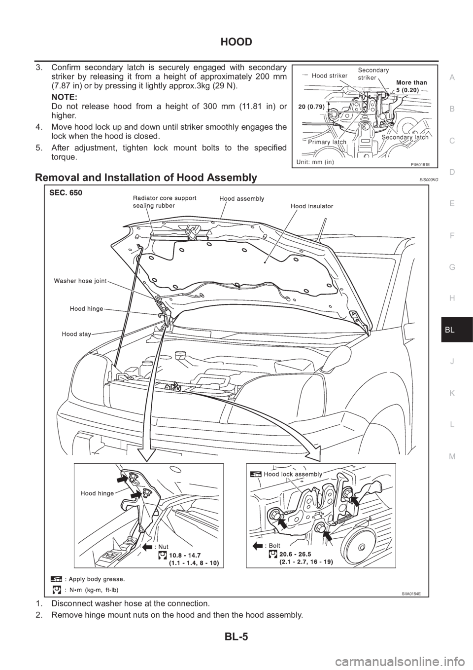
3. Confirm secondary latch is securely engaged with secondary
striker by releasing it from a height of approximately 200 mm
(7.87 in) or by pressing it lightly approx.3kg (29 N).
NOTE:
Do not release hood from a height of 300 mm (11.81 in) or
higher.
4. Move hood lock up and down until striker smoothly engages the
lock when the hood is closed.
5. After adjustment, tighten lock mount bolts to the specified
torque.
Removal and Installation of Hood AssemblyEIS000KG
1. Disconnect washer hose at the connection.
2. Remove hinge mount nuts on the hood and then the hood assembly.
PIIA0181E
SIIA0154E
Page 3786 of 3833

MA-6
GENERAL MAINTENANCE
GENERAL MAINTENANCE
PFP:00000
General MaintenanceELS000AL
General maintenance includes those items which should be checked during the normal day-to-day operation
of the vehicle. They are essential if the vehicle is to continue operating properly. The owners can perform the
checks and inspections themselves or they can have their NISSAN dealers do them for a nominal charge.
OUTSIDE THE VEHICLE
The maintenance items listed here should be performed from time to time, unless otherwise specified.
INSIDE THE VEHICLE
The maintenance items listed here should be checked on a regular basis, such as when performing periodic maintenance, cleaning the
vehicle, etc.
UNDER THE HOOD AND VEHICLE
The maintenance items listed here should be checked periodically e.g. each time you check the engine oil or refuel. Item Reference page
TiresCheck the pressure with a gauge periodically when at a service station, includ-
ing the spare, and adjust to the specified pressure if necessary. Check carefully
for damage, cuts or excessive wear.—
Windshield wiper
bladesCheck for cracks or wear if not functioning correctly. —
Doors and engine
hoodCheck that all doors, the engine hood, the trunk lid and back door operate prop-
erly. Also ensure that all latches lock securely. Lubricate if necessary. Make sure
that the secondary latch keeps the hood from opening when the primary latch is
released.
When driving in areas using road salt or other corrosive materials, check for
lubrication frequently.BL-4
,BL-8
Tire rotationTires should be rotated every 5,000 km (3,000 miles).MA-38
Item Reference page
LampsMake sure that the headlamps, stop lamps, tail lamps, turn signal lamps, and
other lamps are all operating properly and installed securely. Also check head-
lamp aim.—
Warning lamps and
chimesMake sure that all warning lamps and buzzers/chimes are operating properly. —
Steering wheelCheck that it has the specified play.
Check for changes in the steering conditions, such as excessive free play, hard
steering or strange noises.
Free play: Less than 35 mm (1.38 in)—
Seat beltsCheck that all parts of the seat belt system (e.g. buckles, anchors, a dju sters and
retractors) operate properly and smoothly, and are installed securely. Check the
belt webbing for cuts, fraying, wear or damage.SB-3
Item Reference page
Windshield washer
fluidCheck that there is adequate fluid in the tank. —
Engine coolant levelCheck the coolant level when the engine is cold.CO-29
(QR20DE,
QR25DE)
CO-29
(YD22DDTi)
Engine oil levelCheck the level after parking the vehicle (on level ground) and turning off the
engine.LU-18
(QR20DE,
QR25DE)
LU-18
(YD22DDTi)
Brake and clutch fluid
levelsMake sure that the brake and clutch fluid levels are between the “MAX” and
“MIN” lines on the reservoir.MA-35
,MA-39
BatteryCheck the fluid level in each cell. It should be between the “MAX” and “MIN”
lines.—