Battery NISSAN X-TRAIL 2005 Service Repair Manual
[x] Cancel search | Manufacturer: NISSAN, Model Year: 2005, Model line: X-TRAIL, Model: NISSAN X-TRAIL 2005Pages: 4555, PDF Size: 88.09 MB
Page 4502 of 4555

MA-6
GENERAL MAINTENANCE
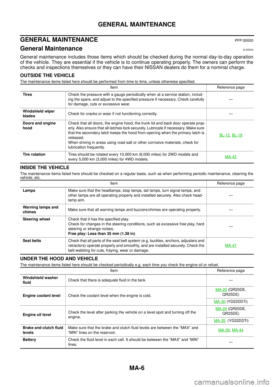
GENERAL MAINTENANCEPFP:00000
General MaintenanceELS000AL
General maintenance includes those items which should be checked during the normal day-to-day operation
of the vehicle. They are essential if the vehicle is to continue operating properly. The owners can perform the
checks and inspections themselves or they can have their NISSAN dealers do them for a nominal charge.
OUTSIDE THE VEHICLE
The maintenance items listed here should be performed from time to time, unless otherwise specified.
INSIDE THE VEHICLE
The maintenance items listed here should be checked on a regular basis, such as when performing periodic maintenance, cleaning the
vehicle, etc.
UNDER THE HOOD AND VEHICLE
The maintenance items listed here should be checked periodically e.g. each time you check the engine oil or refuel.Item Reference page
TiresCheck the pressure with a gauge periodically when at a service station, includ-
ing the spare, and adjust to the specified pressure if necessary. Check carefully
for damage, cuts or excessive wear.—
Windshield wiper
bladesCheck for cracks or wear if not functioning correctly. —
Doors and engine
hoodCheck that all doors, the engine hood, the trunk lid and back door operate prop-
erly. Also ensure that all latches lock securely. Lubricate if necessary. Make sure
that the secondary latch keeps the hood from opening when the primary latch is
released.
When driving in areas using road salt or other corrosive materials, check for
lubrication frequently.BL-12
, BL-18
Tire rotationTires should be rotated every 10,000 km (6,000 miles) for 2WD models and
every 5,000 km (3,000 miles) for 4WD models.MA-43
Item Reference page
LampsMake sure that the headlamps, stop lamps, tail lamps, turn signal lamps, and
other lamps are all operating properly and installed securely. Also check head-
lamp aim.—
Warning lamps and
chimesMake sure that all warning lamps and buzzers/chimes are operating properly. —
Steering wheelCheck that it has the specified play.
Check for changes in the steering conditions, such as excessive free play, hard
steering or strange noises.
Free play: Less than 35 mm (1.38 in)—
Seat beltsCheck that all parts of the seat belt system (e.g. buckles, anchors, adjusters and
retractors) operate properly and smoothly, and are installed securely. Check the
belt webbing for cuts, fraying, wear or damage.MA-47
Item Reference page
Windshield washer
fluidCheck that there is adequate fluid in the tank. —
Engine coolant levelCheck the coolant level when the engine is cold.MA-20
(QR20DE,
QR25DE)
MA-30
(YD22DDTi)
Engine oil levelCheck the level after parking the vehicle on a level spot and turning off the
engine.MA-24
(QR20DE,
QR25DE)
MA-35
(YD22DDTi)
Brake and clutch fluid
levelsMake sure that the brake and clutch fluid levels are between the “MAX” and
“MIN” lines on the reservoir.MA-39
, MA-44
BatteryCheck the fluid level in each cell. It should be between the “MAX” and “MIN”
lines.—
Page 4549 of 4555

IDX-3
A
C
D
E
F
G
H
I
J
K
L B
IDX
ALPHABETICAL INDEX
EC-1641
Basic inspection .. EC-79, EC-578, EC-1012, EC-1382
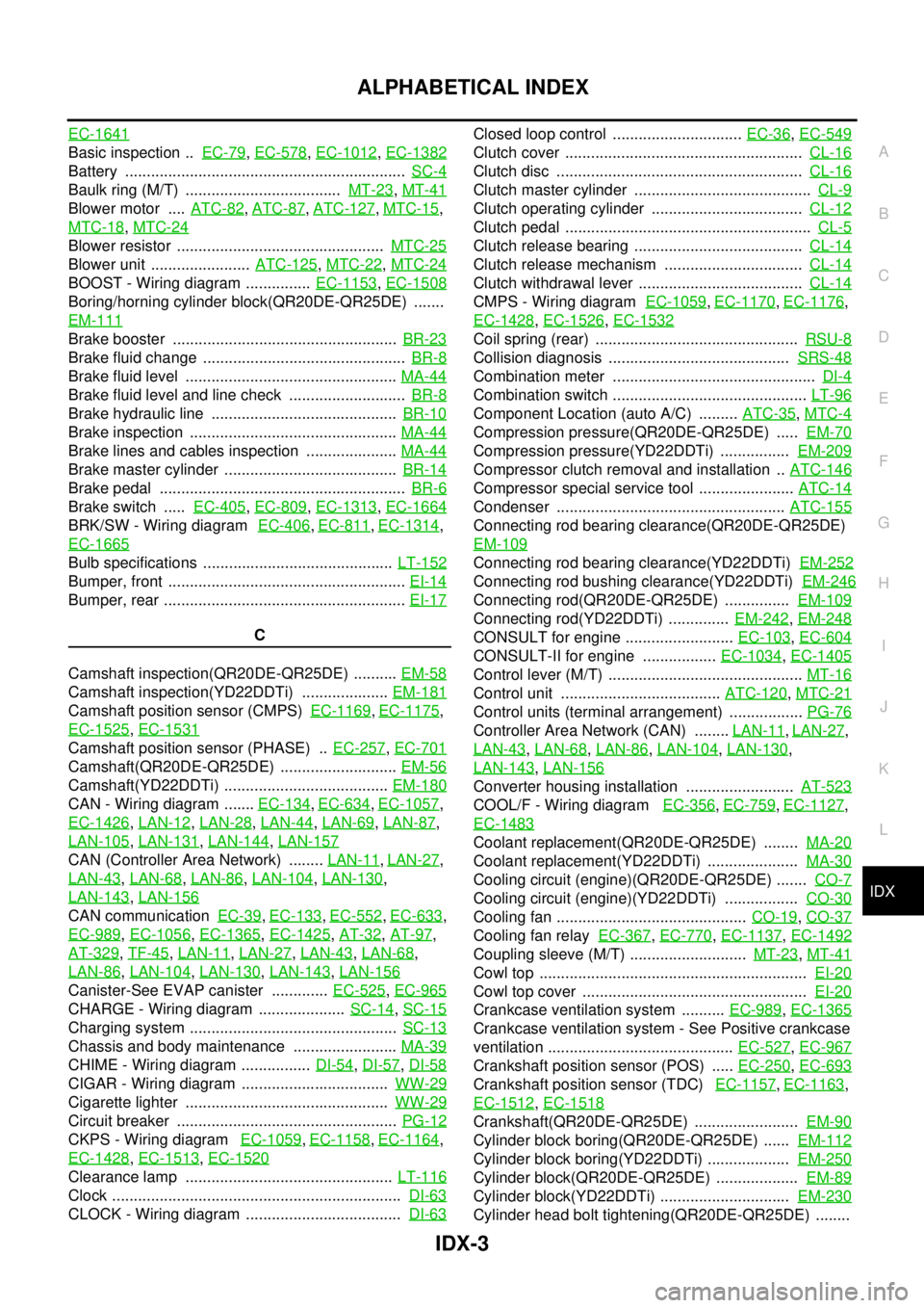
Battery ................................................................. SC-4
Baulk ring (M/T) .................................... MT-23, MT-41
Blower motor .... ATC-82, ATC-87, ATC-127, MTC-15,
MTC-18
, MTC-24
Blower resistor ................................................ MTC-25
Blower unit ....................... ATC-125, MTC-22, MTC-24
BOOST - Wiring diagram ............... EC-1153, EC-1508
Boring/horning cylinder block(QR20DE-QR25DE) .......
EM-111
Brake booster .................................................... BR-23
Brake fluid change ............................................... BR-8
Brake fluid level ................................................. MA-44
Brake fluid level and line check ........................... BR-8
Brake hydraulic line ........................................... BR-10
Brake inspection ................................................ MA-44
Brake lines and cables inspection ..................... MA-44
Brake master cylinder ........................................ BR-14
Brake pedal ......................................................... BR-6
Brake switch ..... EC-405, EC-809, EC-1313, EC-1664
BRK/SW - Wiring diagram EC-406, EC-811, EC-1314,
EC-1665
Bulb specifications ............................................ LT-152
Bumper, front ....................................................... EI-14
Bumper, rear ........................................................ EI-17
C
Camshaft inspection(QR20DE-QR25DE) .......... EM-58
Camshaft inspection(YD22DDTi) .................... EM-181
Camshaft position sensor (CMPS) EC-1169, EC-1175,
EC-1525
, EC-1531
Camshaft position sensor (PHASE) .. EC-257, EC-701
Camshaft(QR20DE-QR25DE) ........................... EM-56
Camshaft(YD22DDTi) ...................................... EM-180
CAN - Wiring diagram ....... EC-134, EC-634, EC-1057,
EC-1426
, LAN-12, LAN-28, LAN-44, LAN-69, LAN-87,
LAN-105
, LAN-131, LAN-144, LAN-157
CAN (Controller Area Network) ........ LAN-11, LAN-27,
LAN-43
, LAN-68, LAN-86, LAN-104, LAN-130,
LAN-143
, LAN-156
CAN communication EC-39, EC-133, EC-552, EC-633,
EC-989
, EC-1056, EC-1365, EC-1425, AT-32, AT-97,
AT-329
, TF-45, LAN-11, LAN-27, LAN-43, LAN-68,
LAN-86
, LAN-104, LAN-130, LAN-143, LAN-156
Canister-See EVAP canister ............. EC-525, EC-965
CHARGE - Wiring diagram .................... SC-14, SC-15
Charging system ................................................ SC-13
Chassis and body maintenance ........................ MA-39
CHIME - Wiring diagram ................ DI-54, DI-57, DI-58
CIGAR - Wiring diagram .................................. WW-29
Cigarette lighter ............................................... WW-29
Circuit breaker ................................................... PG-12
CKPS - Wiring diagram EC-1059, EC-1158, EC-1164,
EC-1428
, EC-1513, EC-1520
Clearance lamp ................................................ LT-116
Clock ................................................................... DI-63
CLOCK - Wiring diagram .................................... DI-63
Closed loop control .............................. EC-36, EC-549
Clutch cover ....................................................... CL-16
Clutch disc ......................................................... CL-16
Clutch master cylinder ......................................... CL-9
Clutch operating cylinder ................................... CL-12
Clutch pedal ......................................................... CL-5
Clutch release bearing ....................................... CL-14
Clutch release mechanism ................................ CL-14
Clutch withdrawal lever ...................................... CL-14
CMPS - Wiring diagram EC-1059, EC-1170, EC-1176,
EC-1428
, EC-1526, EC-1532
Coil spring (rear) ............................................... RSU-8
Collision diagnosis .......................................... SRS-48
Combination meter ............................................... DI-4
Combination switch ............................................. LT-96
Component Location (auto A/C) ......... ATC-35, MTC-4
Compression pressure(QR20DE-QR25DE) ..... EM-70
Compression pressure(YD22DDTi) ................ EM-209
Compressor clutch removal and installation .. ATC-146
Compressor special service tool ...................... ATC-14
Condenser ..................................................... ATC-155
Connecting rod bearing clearance(QR20DE-QR25DE)
EM-109
Connecting rod bearing clearance(YD22DDTi) EM-252
Connecting rod bushing clearance(YD22DDTi) EM-246
Connecting rod(QR20DE-QR25DE) ............... EM-109
Connecting rod(YD22DDTi) .............. EM-242, EM-248
CONSULT for engine ......................... EC-103, EC-604
CONSULT-II for engine ................. EC-1034, EC-1405
Control lever (M/T) ............................................. MT-16
Control unit ..................................... ATC-120, MTC-21
Control units (terminal arrangement) ................. PG-76
Controller Area Network (CAN) ........ LAN-11, LAN-27,
LAN-43
, LAN-68, LAN-86, LAN-104, LAN-130,
LAN-143
, LAN-156
Converter housing installation ......................... AT-523
COOL/F - Wiring diagram EC-356, EC-759, EC-1127,
EC-1483
Coolant replacement(QR20DE-QR25DE) ........ MA-20
Coolant replacement(YD22DDTi) ..................... MA-30
Cooling circuit (engine)(QR20DE-QR25DE) ....... CO-7
Cooling circuit (engine)(YD22DDTi) ................. CO-30
Cooling fan ............................................ CO-19, CO-37
Cooling fan relay EC-367, EC-770, EC-1137, EC-1492
Coupling sleeve (M/T) ........................... MT-23, MT-41
Cowl top .............................................................. EI-20
Cowl top cover .................................................... EI-20
Crankcase ventilation system .......... EC-989, EC-1365
Crankcase ventilation system - See Positive crankcase
ventilation ........................................... EC-527
, EC-967
Crankshaft position sensor (POS) ..... EC-250, EC-693
Crankshaft position sensor (TDC) EC-1157, EC-1163,
EC-1512
, EC-1518
Crankshaft(QR20DE-QR25DE) ........................ EM-90
Cylinder block boring(QR20DE-QR25DE) ...... EM-112
Cylinder block boring(YD22DDTi) ................... EM-250
Cylinder block(QR20DE-QR25DE) ................... EM-89
Cylinder block(YD22DDTi) .............................. EM-230
Cylinder head bolt tightening(QR20DE-QR25DE) ........