air condition NISSAN XTERRA 2000 WD22 / 1.G Owners Manual
[x] Cancel search | Manufacturer: NISSAN, Model Year: 2000, Model line: XTERRA, Model: NISSAN XTERRA 2000 WD22 / 1.GPages: 263, PDF Size: 2.16 MB
Page 6 of 263

Table of
ContentsSeats, restraints and supplemental air bag systems
Instruments and controls
Pre-driving checks and adjustments
Heater, air conditioner and audio systems
Starting and driving
In case of emergency
Appearance and care
Do-it-yourself
Maintenance
Technical and consumer information
Index
1
2
3
4
5
6
7
8
9
10
11
Page 16 of 263

The driver supplemental air bag is located in
the center of the steering wheel. The pas-
senger supplemental air bag is located in
the top right section of the instrument panel.
These systems are designed to meet optional
certification requirements under U.S. regula-tions. They are also permitted in Canada. The
optional certification allows air bags to be
designed to inflate somewhat less forcefully
than previously.However, all of the informa-
tion, cautions and warnings in this manual
still apply and must be followed.
The supplemental air bag system is de-
signed to inflate in higher severity frontal
collisions, although it may inflate if the
forces in another type of collision are similar
to those of a higher severity frontal impact. It
may not inflate in certain frontal collisions.
Vehicle damage (or lack of it) is not always
an indication of proper supplemental air bag
system operation.
When the supplemental air bag inflates, a
fairly loud noise may be heard, followed by
the release of smoke. This smoke is not
harmful and does not indicate a fire, but
care should be taken not to intentionally
inhale it, as it may cause irritation and
choking. Those with a history of a breathing
condition should get fresh air promptly.
The supplemental air bags, along with the
use of the seat belts, helps to cushion the
impact force on the face and chest of the
occupant. It can help save lives and reduce
serious injuries. However, an inflating sup-
plemental air bag may cause facial abrasions
or other injuries. Supplemental air bags do
not provide restraint to the lower body.
Seat belts should be correctly worn and the
driver and passenger seated upright as far
as practical away from the steering wheel or
instrument panel. Since the supplemental air
ARS1228
SUPPLEMENTAL AIR BAG
SYSTEM
Seats, restraints and supplemental air bag systems1-9
ZX
Page 18 of 263

Warning labels about the supplemental air
bag system are placed in the vehicle as
shown in the illustration.The supplemental air bag warning light,
displaying
in the instrument panel,
monitors the circuits of the supplemental air
bag system. The circuits monitored by the
supplemental air bag warning light are the
diagnosis sensor unit, the supplemental air
bag modules and all related wiring.
When the ignition key is in the ON or START
position, the supplemental air bag warning
light illuminates for about 7 seconds and
then turns off. This means the system is
operational.
If any of the following system conditions
occur, the supplemental air bag system
ARS1229
ARS1230
WARNING LABELS SUPPLEMENTAL AIR BAG
WARNING LIGHT
Seats, restraints and supplemental air bag systems1-11
ZX
Page 19 of 263

needs servicing and should be taken to an
authorized NISSAN dealer:
OThe supplemental air bag warning light
remains on after approximately 7 sec-
onds.
OThe supplemental air bag warning light
flashes intermittently.
OThe supplemental air bag warning light
does not come on at all.
Under these conditions, the Supplemental
Restraint System (supplemental air bag
system) may not function properly. It must
be checked and repaired.
WARNING
If the supplemental air bag warning
light is on, it could mean that the
supplemental air bag system will not
operate in an accident.
Repair and replacement procedure
The supplemental air bag modules are de-
signed to inflate on a one-time-only basis.
As a reminder, unless it is damaged, the
supplemental air bag warning light remains
illuminated after inflation has occurred.Repair and replacement of the supplemen-
tal air bag system should be done only by
an authorized NISSAN dealer.
To ensure long-term functioning, the
supplemental air bag system must be
inspected 10 years after the date of
manufacture noted on the certification
label located on the driver side door
jamb pillar.
When maintenance work is required on the
vehicle, the supplemental air bag system
and related parts should be pointed out to
the person conducting the maintenance. The
ignition key must always be in the LOCK
position when working under the hood or
inside the vehicle.
WARNING
OOnce the supplemental air bag in-
flates, the supplemental air bag
module will not function again and
should be replaced by an authorized
NISSAN dealer. The supplemental air
bag module cannot be repaired.OThe supplemental air bag system
should be inspected by an autho-
rized NISSAN dealer if there is any
damage to the front end portion of
the vehicle, or replaced if the supple-
mental air bag has inflated.
OIf you need to dispose of the supple-
mental air bag or scrap the vehicle,
contact an authorized NISSAN
dealer. Correct supplemental air bag
disposal procedures are set forth in
the appropriate NISSAN Service
Manual. Incorrect disposal proce-
dures could cause personal injury.
1-12Seats, restraints and supplemental air bag systems
ZX
Page 51 of 263

Turn signal/hazard indicator
lights
These lights flash when the turn signal
switch or hazard switch is turned on.
orBrake warning
light
This light functions for both the parking
brake and the foot brake systems.
When the ignition key is in the ON position,
the light comes on when the parking brake
is applied and also warns of a low brake
fluid level. If the light comes on while the
engine is running with the parking brake not
applied, stop the vehicle and perform the
following.
1.
Check the brake fluid level. Add brake fluid
as necessary. See ``Brake and clutch fluid''
in the ``Do-it-yourself'' section of this
manual.
2. If the brake fluid level is correct, have the
warning system checked by an autho-
rized NISSAN dealer.
WARNING
OYour brake system may not be work-
ing properly if the warning light is
on. Driving could be dangerous. If
you judge it to be safe, drive care-
fully to the nearest service station
for repairs. Otherwise have your ve-
hicle towed because driving it could
be dangerous.
OPressing the brake pedal with the
engine stopped and/or low brake
fluid level may increase your stop-
ping distance and require greater
pedal effort as well as pedal travel.
OIf the brake fluid level is below the
MINIMUM or MIN mark on the brake
fluid reservoir, do not drive until the
brake system has been checked at
an authorized NISSAN dealer.
High beam indicator light
This blue light comes on when the headlight
high beams are on and goes out when the
low beams are selected.
The high beam indicator light also comes on
when the passing signal is activated.
Seat belt warning light and
chime
The light and chime remind you to fasten
your seat belts. If the driver's seat belt is
NOT securely fastened when the ignition
key is turned to ON or START, the chime
sounds five times and the light illuminates.
If the driver's seat belt is fastened before the
ignition key is turned to the ON postion, the
light will not come on briefly and then
go off.
Supplemental air bag
warning light
When the ignition key is in the ON or START
position, the supplemental air bag warning
light illuminates for about 7 seconds and
then turns off. This means the system is
operational.
If any of the following conditions occur, the
supplemental restraint system needs ser-
vicing and your vehicle must be taken to an
authorized authorized NISSAN dealer.
OThe supplemental air bag warning light
remains on after approximately 7 sec-
onds.
2-8Instruments and controls
ZX
Page 90 of 263

4Heater, air conditioner and audio systems
Ventilators ...............................................................4-2
Heater and air conditioner......................................4-3
Controls ..................................................................4-3
Heater operation ....................................................4-4
Air conditioner operation (if so equipped) ..............4-5
Air flow charts.........................................................4-6
Audio system ........................................................4-10
AM-FM radio with cassette player .......................4-10
Cassette tape operation .......................................4-13
FM-AM radio with compact disc (CD) player
(if so equipped) ....................................................4-15
Compat disc CD player operation ........................4-19CD care and cleaning ..........................................4-20
AM-FM radio with compact disc player
(if so equipped) ....................................................4-22
Compact disc (CD) player operation....................4-25
CD care and cleaning ..........................................4-26
AM-FM radio with cassette player and
compact disc player (if so equipped) ...................4-28
Cassette tape operation .......................................4-32
Compact disc (CD) player operation....................4-33
CD care and cleaning ..........................................4-35
Antenna ................................................................4-35
Car phone or CB radio .........................................4-36
ZX
Page 91 of 263

Adjust air flow direction by moving the ven-
tilators slides and ventilator assemblies.
AHA1099
VENTILATORS
4-2Heater, air conditioner and audio systems
ZX
Page 92 of 263

WARNING
OThe air conditioner cooling function
operates only when the engine is
running.
ODo not leave children, unreliable
adults, or pets alone in your vehicle.
On hot sunny days, temperatures in
a closed vehicle could quickly be-
come high enough to cause severe
or possibly fatal injuries to people or
animals.
ODo not use the recirculation mode
for long periods as it may cause theinterior air to become stale and the
windows to fog up.
OPositioning of the heater or air con-
ditioner controls should not be done
while driving, in order that full atten-
tion may be given to the driving
operation.
CONTROLS
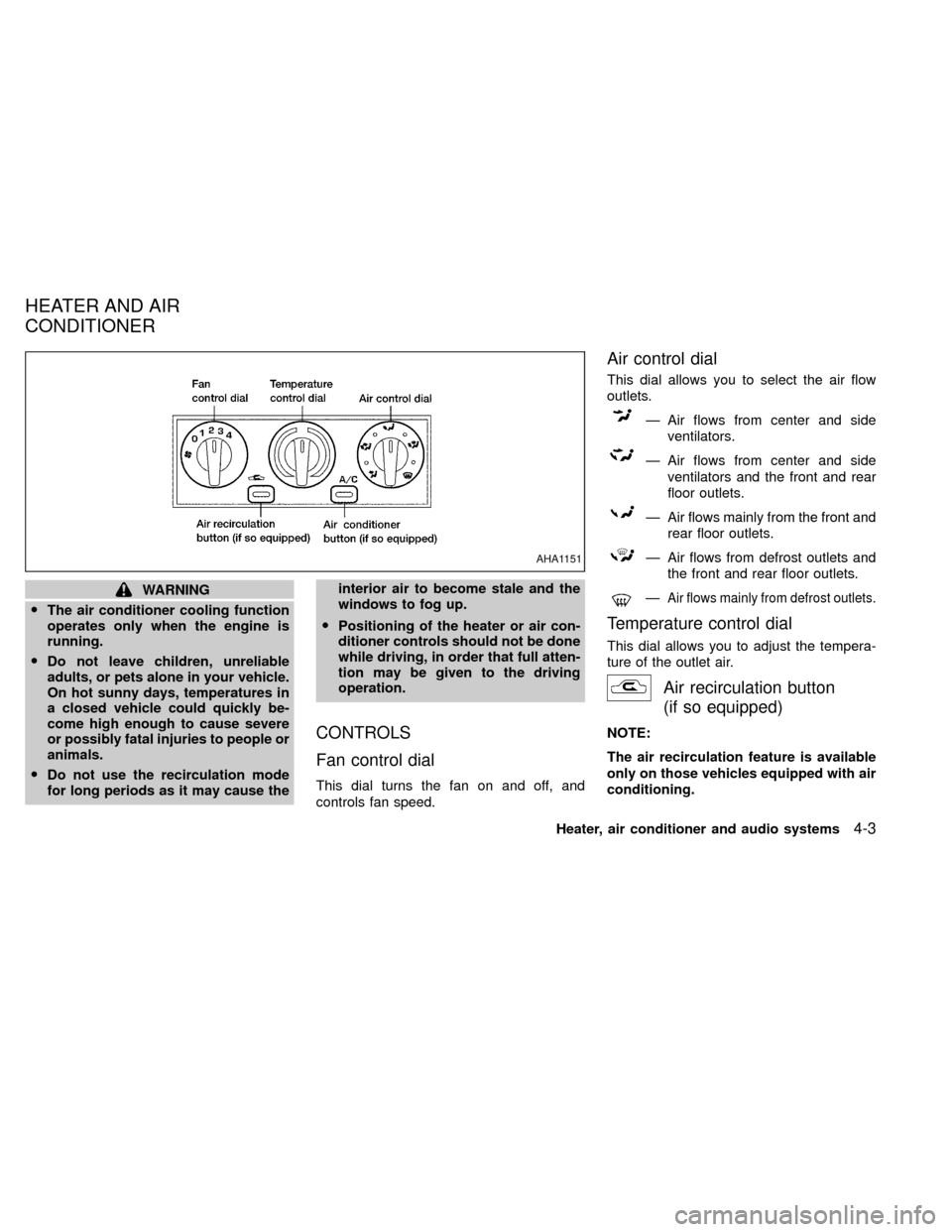
Fan control dial
This dial turns the fan on and off, and
controls fan speed.
Air control dial
This dial allows you to select the air flow
outlets.
Ð Air flows from center and side
ventilators.
Ð Air flows from center and side
ventilators and the front and rear
floor outlets.
Ð Air flows mainly from the front and
rear floor outlets.
Ð Air flows from defrost outlets and
the front and rear floor outlets.
ÐAir flows mainly from defrost outlets.
Temperature control dial
This dial allows you to adjust the tempera-
ture of the outlet air.
Air recirculation button
(if so equipped)
NOTE:
The air recirculation feature is available
only on those vehicles equipped with air
conditioning.
AHA1151
HEATER AND AIR
CONDITIONER
Heater, air conditioner and audio systems4-3
ZX
Page 93 of 263

OFF position (indicator light off):
Outside air is drawn into the passenger
compartment and distributed through the
selected outlets.
Use the OFF position for normal heater or
air conditioner operation.
ON position (indicator light on):
Interior air is recirculated inside the vehicle.
Push the
button to the on position
when:
Odriving on a dusty road.
Oto prevent traffic fumes from entering the
passenger compartment.
Ofor maximum cooling when using the air
conditioner.
Air conditioner button
(if so equipped)
Start the engine, move the fan control dial to
the desired (one to four) position, and push
the air conditioner button to turn on the air
conditioner. The indicator light comes on
when the air conditioner is operating. To turn
off the air conditioner, push the button
again.The air conditioner cooling function op-
erates only when the engine is running.
HEATER OPERATION
Heating
This mode is used to direct most of the hot
air to the front and rear floor outlets. Rear
passenger heat is provided by the front
system through floor outlets located under
both front seats. A small amount of air also
flows from the defrost outlets.
1. Push the
button (if so equipped) to
the off position for normal heating.
2. Turn the air control dial to the
po-
sition.
3. Turn the fan control dial to the desired
position.
4. Turn the temperature control dial to the
desired position between the middle and
the hot position.
Ventilation
This mode directs outside air from the side
and center vents.
1. Push the
button (if so equipped) to
the off position.2. Turn the air control dial to the
po-
sition.
3. Turn the fan control dial to the desired
position.
4. Turn the temperature control dial to the
desired position.
Defrosting/defogging
This mode directs the air to the defrost
outlets to defrost/defog the windows.
1. Turn the air control dial to the
posi-
tion.
2. Turn the fan control dial to the desired
position.
3. Turn the temperature control dial to the
desired position.
When the
position is selected, the air
conditioner automatically turns on (however
the indicator light will not illuminate) if the
outside temperature is more than
45ÉF(7ÉC). This dehumidifies the air which
helps defog the windshield. The
mode automatically turns off, allow-
ing outside air to be drawn into the passen-
ger compartment to further improve the
defogging performance.
4-4Heater, air conditioner and audio systems
ZX
Page 94 of 263

Bi-level heating
The bi-level mode directs warmed air to the
side and center vents and to the front and
rear floor outlets.
1. Push the
button (if so equipped) to
the off position.
2. Turn the air control dial to the
posi-
tion.
3. Turn the fan control dial to the desired
position.
4. Turn the temperature control dial to the
the desired position.
Heating and defrosting/defogging
This mode directs a portion of the air to the
defrost outlets to defrost/defog the win-
dows, and also directs air to the front and
rear floor outlets to heat the cabin.
1. Turn the air control dial to the
po-
sition.
2. Turn the fan control dial to the desired
position.
3. Turn the temperature control dial to the
desired position between the middle and
the hot position.When the
position is selected, the air
conditioner automatically turns on (however
the indicator light will not illuminate) if the
outside temperature is more than 45ÉF
(7ÉC). This dehumidifies the air which helps
defog the windshield. The
mode au-
tomaticallly turns off, allowing outside air to
be drawn into the passenger compartment
to further improve the defogging perfor-
mance.
Operating tips
Clear snow and ice from the wiper
blades and air inlet in front of the wind-
shield. This improves heater operation.
AIR CONDITIONER OPERATION
(if so equipped)
Start the engine, move the fan control dial to
the desired (one to four) position, and push
in the air conditioner button to activate the
air conditioner. When the air conditioner is
on, cooling and dehumidifying functions are
added to the heater operation.
The air conditioner cooling function op-
erates only when the engine is running.
Cooling
This mode directs cooled and dryed air to
the side and center vents to cool and dehu-
midify the cabin.
1. Push the
button to the off position.
2. Turn the air control dial to the
posi-
tion.
3. Turn the fan control dial to the desired
position.
4. Push on the air conditioner button. The
indicator light comes on.
5. Turn the temperature control dial to the
desired position.
For quick cooling when the outside tem-
perature is high, push the
button to the
ON position. Be sure to return the air recir-
culation button to the OFF position for nor-
mal cooling.
Dehumidified heating
This mode directs warmed and dryed air to
the front and rear floor outlets to heat and
dehumidify the cabin.
1. Push the
button to the off position.
Heater, air conditioner and audio systems
4-5
ZX