clock NISSAN XTERRA 2002 WD22 / 1.G User Guide
[x] Cancel search | Manufacturer: NISSAN, Model Year: 2002, Model line: XTERRA, Model: NISSAN XTERRA 2002 WD22 / 1.GPages: 263, PDF Size: 2.22 MB
Page 130 of 263

audio control switch. Press the top of the
volume control to increase volume. Press
the bottom of the volume control to de-
crease volume.
ANTENNA
The antenna cannot be shortened, but it can
be removed. When you need to remove the
antenna, turn the antenna rod counterclock-
wise.
To install the antenna rod, turn the antenna
clockwise. Tighten the antenna rod to speci-
fication using a suitable tool such as a
open-end wrench. The antenna rod tighten-
ing specification is 2.0 - 2.6 Nzm(18-23
in-lb). Do not use pliers to tighten the an-
tenna as they can leave marks on the
antenna surface. The antenna rod can not
be hand tightened to the proper specifica-
tion.
CAUTION
Always properly tighten the antenna
rod during installation or the antenna
rod may break during vehicle opera-
tion.When installing a CB, ham radio or car
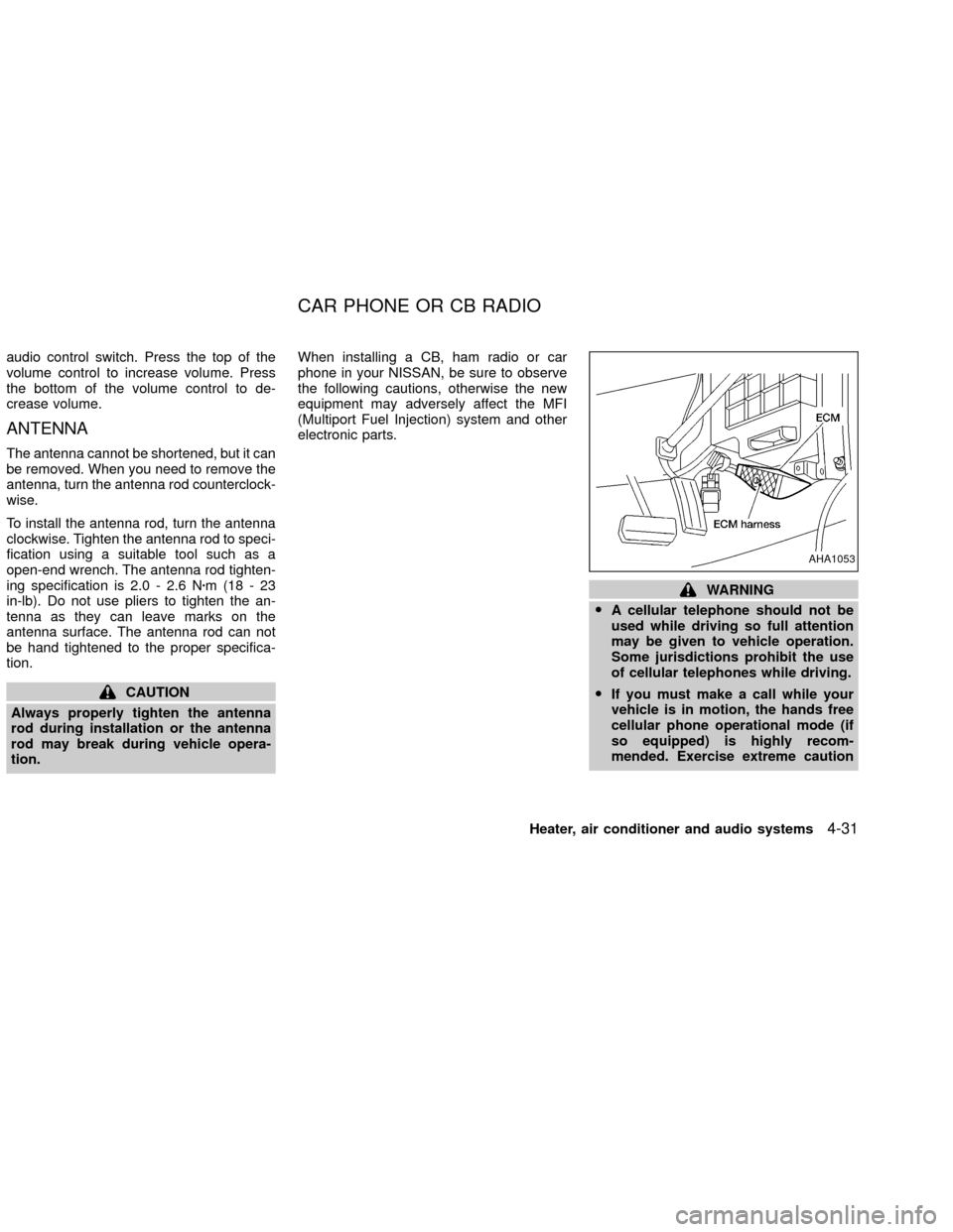
phone in your NISSAN, be sure to observe
the following cautions, otherwise the new
equipment may adversely affect the MFI
(Multiport Fuel Injection) system and other
electronic parts.
WARNING
OA cellular telephone should not be
used while driving so full attention
may be given to vehicle operation.
Some jurisdictions prohibit the use
of cellular telephones while driving.
OIf you must make a call while your
vehicle is in motion, the hands free
cellular phone operational mode (if
so equipped) is highly recom-
mended. Exercise extreme caution
AHA1053
CAR PHONE OR CB RADIO
Heater, air conditioner and audio systems4-31
ZX
Page 138 of 263

In order for the steering wheel to be locked,
it must be turned about 1/8 of a turn clock-
wise from the straight up position.
To lock the steering wheel, turn the key
to the LOCK position. Remove the key.
To unlock the steering wheel, insert the
key and turn it gently while rotating the
steering wheel slightly right and left.
WARNING
Never remove or turn the key to the
LOCK position while driving. The steer-
ing wheel will lock. This may cause the
driver to lose control of the vehicle and
could result in serious vehicle damage
or personal injury.
MANUAL TRANSMISSION
The ignition switch includes an anti-theft
steering lock device.
The key can only be removed when the
ignition switch is in the LOCK position.
On manual transmission models, to turn the
ignition key to LOCK from ACC or ON, turn
the key to OFF, push the key in, then turn
the key to LOCK.
In order for the steering wheel to be locked,
it must be turned about 1/8 of a turn clock-
wise from the straight up position.To lock the steering wheel, turn the key
to the LOCK position. Remove the key.
To unlock the steering wheel, insert the
key and turn it gently while rotating the
steering wheel slightly right and left.
WARNING
Never remove or turn the key to the
LOCK position while driving. The steer-
ing wheel will lock. This may cause the
driver to lose control of the vehicle and
could result in serious vehicle damage
or personal injury.
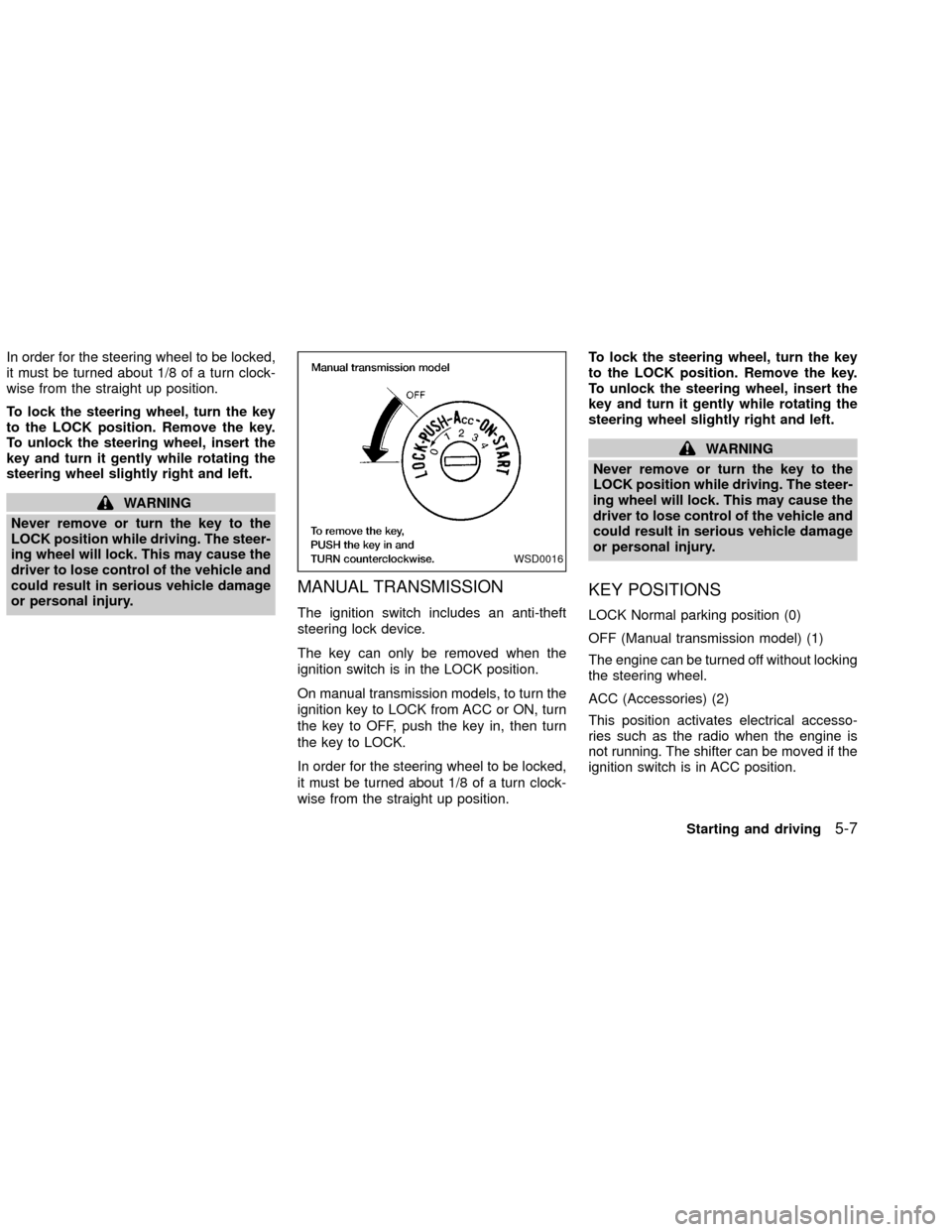
KEY POSITIONS
LOCK Normal parking position (0)
OFF (Manual transmission model) (1)
The engine can be turned off without locking
the steering wheel.
ACC (Accessories) (2)
This position activates electrical accesso-
ries such as the radio when the engine is
not running. The shifter can be moved if the
ignition switch is in ACC position.
WSD0016
Starting and driving5-7
ZX
Page 166 of 263

rod engaged in the spare tire winch and
turn the jack rod counter clockwise to
lower the spare tire.
10.Once the spare tire is completely low-
ered, reach under the vehicle, remove
the retainer chain, and carefully slide the
tire from under the rear of the vehicle.
CAUTION
Be sure to center the spare tire sus-
pending plate on the wheel and then lift
the spare tire.
CE0047MACE1040
In case of emergency6-5
ZX
Page 215 of 263

FCC Notice:
Changes or modifications not expressly
approved by the manufacturer for com-
pliance could void the user's authority to
operate the equipment.
This device complies with part 15 of the
FCC Rules and RSS-210 of Industry
Canada.
Operation is subject to the following two
conditions: (1) This device may not
cause harmful interference, and (2) this
device must accept any interference re-
ceived including interference that may
cause undesired operation of the device.
HEADLIGHTS
The headlight is a semi-sealed beam type
which uses a replaceable headlight (halo-
gen) bulb.
CAUTION
OHigh pressure halogen gas is sealed
inside the halogen bulb. The bulb
may break if the glass envelope is
scratched or the bulb is dropped.
OWhen handling the bulb, do not
touch the glass envelope.
Replacing the headlight bulb
1. Open the engine hood.
2. Disconnect the negative (2) battery
cable.
3. Disconnect the electrical connector from
the rear end of the bulb.
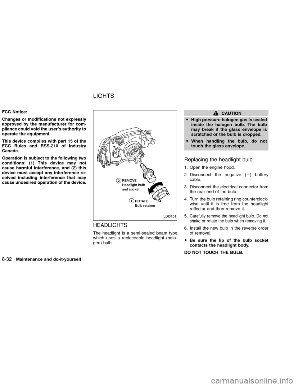
4. Turn the bulb retaining ring counterclock-
wise until it is free from the headlight
reflector and then remove it.
5.
Carefully remove the headlight bulb. Do not
shake or rotate the bulb when removing it.
6. Install the new bulb in the reverse order
of removal.
OBe sure the lip of the bulb socket
contacts the headlight body.
DO NOT TOUCH THE BULB.
LDI0101
LIGHTS
8-32Maintenance and do-it-yourself
ZX