glove box NISSAN XTERRA 2002 WD22 / 1.G Owners Manual
[x] Cancel search | Manufacturer: NISSAN, Model Year: 2002, Model line: XTERRA, Model: NISSAN XTERRA 2002 WD22 / 1.GPages: 263, PDF Size: 2.22 MB
Page 47 of 263

2 Instruments and controls
Instrument panel ....................................................2-2
Meters and gauges ................................................2-3
Speedometer and odometer .............................2-3
Tachometer ........................................................2-5
Engine coolant temperature gauge ...................2-5
Fuel gauge ........................................................2-6
Compass and outside temperature display
(if so equipped) ......................................................2-6
Outside temperature display .............................2-6
Compass display ...............................................2-7
Warning/indicator lights and audible
reminders..............................................................2-10
Checking bulbs ................................................2-10
Warning lights .................................................. 2-11
Indicator lights .................................................2-13
Audible reminders............................................2-14
Security system ....................................................2-15
Vehicle security system (if so equipped).........2-15
Windshield wiper and washer switch ...................2-18
Switch operation ..............................................2-18
Rear window wiper and washer switch................2-19
Rear window defogger switch ..............................2-20Headlight and turn signal switch ..........................2-20
Headlight switch ..............................................2-20
Turn signal switch............................................2-21
Front fog light switch (if so equipped)..................2-22
Hazard warning flasher switch .............................2-22
Horn ......................................................................2-23
Cigarette lighter and ash tray (accessories) ........2-23
Power point (if so equipped) ................................2-24
Storage .................................................................2-25
Map pocket ......................................................2-25
Cup holders .....................................................2-26
Glove box ........................................................2-27
Console box (if so equipped) ..........................2-27
Luggage hooks (if so equipped) .....................2-28
Tonneau cover (if so equipped).......................2-29
Windows .............................................................2-30
Power windows (if so equipped) .....................2-30
Manual windows ..............................................2-31
Sunroof (if so equipped).......................................2-32
Tilting the sunroof ............................................2-32
Removing/installing..........................................2-33
Interior light...........................................................2-33
ZX
Page 49 of 263

1. Headlight/turn signal switch
2. Meters and gauges
3. Windshield wiper/washer switch
4. Power point
5. Heater and air conditioner
6. Front passenger supplemental air bag
7. Glove box
8. Audio system
9. Hazard warning flasher switch
10. Automatic/manual selector lever
11. Transfer cased shift lever
12. Parking brake release lever
13. Cruise control main/set switch
14. Driver supplemental air bag
15. Steering wheel switch for audio controls
WIC0150
INSTRUMENT PANEL
2-2Instruments and controls
ZX
Page 74 of 263

GLOVE BOX
Open the glove box by pulling the handle.
WARNING
Keep glove box lid closed while driving
to prevent injury in an accident or a
sudden stop.
CONSOLE BOX (if so equipped)
WARNING
The center console box should not be
used while driving so full attention may
be given to vehicle operation.
CAUTION
cThis power socket is not designed
for use with a cigarette lighter unit.
cDo not use accessories that exceed
12 volt, 120W (10A) power draw. Do
not use double adapters or more
than one electrical accessory.
Upper half
Pull up on the lever to open the upper half of
the console box. The rubber mat may be
removed for cleaning.
LIC0098
LIC0128
Instruments and controls2-27
ZX
Page 169 of 263

COLD pressure:
After vehicle has been parked for three
hours or more or driven less than 1 mile
(1.6 km).
COLD tire pressures are shown on the
tire placard affixed to the inside of the
glove box lid.
ORetighten the wheel nuts when the
vehicle has been driven for 600 miles
(1,000 km) (also in cases of a flat tire,
etc.).
5. Securely store the flat tire and jacking
equipment in the vehicle.
WARNING
Always make sure that the spare tire
and jacking equipment are properly se-
cured after use. Such items can be-
come dangerous projectiles in an acci-
dent or sudden stop.To start your engine with a booster battery,
the instructions and precautions below must
be followed.
WARNING
OIf done incorrectly, jump starting can
lead to a battery explosion, resulting
in severe injury or death. It could
also damage your vehicle.
OExplosive hydrogen gas is always
present in the vicinity of the battery.
Keep all sparks and flames away
from the battery.
ODo not allow battery fluid to come
into contact with eyes, skin, clothing
or painted surfaces. Battery fluid is a
corrosive sulphuric acid solution
which can cause severe burns. If the
fluid should come into contact with
anything, immediately flush the con-
tacted area with water.
OKeep battery out of the reach of
children.
OThe booster battery must be rated at
12 volts. Use of an improperly rated
battery can damage your vehicle.OYour vehicle has and automatic en-
gine cooling fan. It could come on at
any time. Keep hands and other ob-
jects away from it.
OWhenever working on or near a bat-
tery, always wear suitable eye pro-
tectors (for example, goggles or in-
dustrial safety spectacles) and
remove rings, metal bands, or any
other jewelry. Do not lean over the
battery when jump starting.
ODo not attempt to jump start a frozen
battery. It could explode and cause
serious injury.
WARNING
Always follow the instructions be-
low. Failure to do so could result in
damage to the charging system and
cause personal injury.
1.
If the booster battery is in another vehicle,
position the two vehicles to bring their
batteries into close proximity to each other.
Do not allow the two vehicles to touch.
2. Apply the parking brake. Move the shift
selector lever to N (Neutral) (on auto-
JUMP STARTING
6-8In case of emergency
ZX
Page 220 of 263
If you have a flat tire, see the ``In case of
emergency'' section of this manual.
TIRE PRESSURE
Maximum inflation pressure
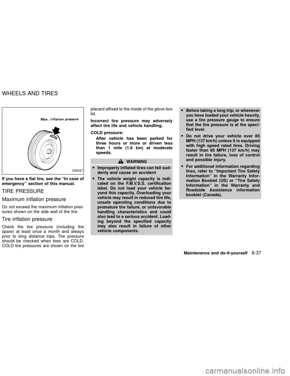
Do not exceed the maximum inflation pres-
sures shown on the side wall of the tire.
Tire inflation pressure
Check the tire pressure (including the
spare) at least once a month and always
prior to long distance trips. Tire pressure
should be checked when tires are COLD.
COLD tire pressures are shown on the tireplacard affixed to the inside of the glove box
lid.
Incorrect tire pressure may adversely
affect tire life and vehicle handling.
COLD pressure:
After vehicle has been parked for
three hours or more or driven less
than 1 mile (1.6 km) at moderate
speeds.
WARNING
OImproperly inflated tires can fail sud-
denly and cause an accident
O
The vehicle weight capacity is indi-
cated on the F.M.V.S.S. certification
label. Do not load your vehicle be-
yond this capacity. Overloading your
vehicle may result in reduced tire life,
unsafe operating conditions due to
premature tire failure, or unfavorable
handling characteristics and could
also lead to a serious accident. Load-
ing beyond the specified capacity
may also result in failure of other
vehicle components.OBefore taking a long trip, or whenever
you have loaded your vehicle heavily,
use a tire pressure gauge to ensure
that the tire pressure is at the speci-
fied level.
ODo not drive your vehicle over 85
MPH (137 km/h) unless it is equipped
with high speed rated tires. Driving
faster than 85 MPH (137 km/h) may
result in tire failure, loss of control
and possible injury.
OFor additional information regarding
tires, refer to ``Important Tire Safety
Information'' in the Warranty Infor-
mation Booklet (US) or ``Tire Safety
Information'' in the Warranty and
Roadside Assistance information
booklet (Canada).
DI0047
WHEELS AND TIRES
Maintenance and do-it-yourself8-37
ZX
Page 239 of 263

EMISSION CONTROL
INFORMATION LABEL
The emission control information label is
attached to the underside of the hood as
shown.
TIRE PLACARD
The cold tire pressure is shown on the tire
placard affixed to the inside of the glove box
lid.
AIR CONDITIONER
SPECIFICATION LABEL
The label is attached to the underside of the
hood as shown.
WTI0014LTI0023WTI0015
9-14Technical and consumer information
ZX
Page 240 of 263

Use the following steps to mount the front
license plate:
1. Remove the two screw gromments from
the glove box.
2. Carefully drill a hole using a 0.39 inch (10
mm) drill bill at each location mark (small
dimple) on the bumper fascia.
3. Insert one grommet into each hole.
4. Insert a small screwdriver into the grom-
met to turn the plastic insert.
5. Install the license plate with two M5 x 25
mm bolts.WARNING
OIt is extremely dangerous to ride in a
cargo area inside of a vehicle. In a
collision, people riding in these ar-
eas are more likely to be seriously
injured or killed.
ODo not allow people to ride in any
area of your vehicle that is not
equipped with seats and seat belts.
O
Be sure everyone in the vehicle is in a
seat with their seat belt properly fas-
tened.
TERMS
It is important to familiarize yourself with the
following terms before loading your vehicle.
OCurb Weight (actual weight of your
vehicle) þ vehicle weight including:
standard and optional equipment, fluids,
emergency tools, and spare tire
assembly. This weightdoes notinclude
passengers and cargo.
OGVW (Gross Vehicle Weight) þ curb
weight plus the combined weight of
passengers and cargo.
WTI0030
INSTALLING FRONT LICENSE
PLATEVEHICLE LOADING
INFORMATION
Technical and consumer information9-15
ZX
Page 243 of 263

PAYLOAD WEIGHT CAPACITY
The payload weight capacity is the maxi-
mum total weight of passengers, optional
equipment (air conditioning, trailer hitch,
etc) and cargo that your vehicle is designed
to carry.
Before driving a loaded vehicle, confirm that
you do not exceed the Gross Vehicle Weight
Rating (GVWR) or the Gross Axle Weight
Rating (GAWR) for your vehicle. See ``Ve-
hicle Loading Information'' earlier in this
section for details.
Also check tires for proper inflation pres-
sures. See the tire placard affixed to the
glove box lid.
Payload Weight Capacity
2WD 4WD
KA24DE VG33E
Manual
TransmissionManual
TransmissionAutomatic
TransmissionManual
TransmissionAutomatic
Transmission
XE XE SE XE SE
lbs kg lbs kg lbs kg lbs kg lbs kg
Federal 1,235 560 1,080 490 1,080 490 981 445 981 445
California 1,235 560 1,080 490 1,080 490 981 445 981 445
Canada N/A N/A 1,001 454 1,001 454 970 440 970 440
Payload Weight Capacity VG33ER
2WD 4WD
lbs kg lbs kg
Federal 992 450 926 420
California 992 450 926 420
Canada 1001 454 882 400
9-18Technical and consumer information
ZX
Page 247 of 263
TOWING SAFETY
Trailer hitch
Check the towing capacity of your bumper
hitch or receiver-type frame mounted hitch.
Choose a proper hitch for your vehicle and
trailer. A genuine Nissan trailer hitch is avail-
able from your NISSAN dealer. Make sure
the trailer hitch is securely attached to the
vehicle to help avoid personal injury or
property damage due to sway caused by
crosswinds, rough road surfaces or passing
trucks.
CAUTION
OSpecial hitches which include frame
reinforcements are required for tow-
ing above 2,000 lb (907 kg). Suitable
genuine NISSAN hitches for pickup
trucks and sport utility vehicles are
available at an authorized NISSAN
dealer.
OThe hitch should not be attached to
or affect the operation of the impact-
absorbing bumper.
ODo not use axle-mounted hitches.ODo not modify the vehicle exhaust
system, brake system, etc. to install
a trailer hitch.
OTo reduce the possibility of addi-
tional damage if your vehicle is
struck from the rear, where practical,
remove the hitch and/or receiver
when not in use.
OAfter the hitch is removed, seal the
bolt holes to prevent exhaust fumes,
water or dust from entering the pas-
senger compartment.
ORegularly check that all trailer hitch
mounting bolts are securely
mounted.
Tire pressures
OWhen towing a trailer, inflate the vehicle
tires to the recommended cold tire pres-
sure indicated on the tire placard (affixed
to the inside of the glove box lid).
OTrailer tire condition, size, load rating and
proper inflation pressure should be in
accordance with the trailer and tire
manufacturers' specifications.
Safety chain
Always use suitable safety chains between
your vehicle and the trailer. Safety chains
should be crossed and should be attached
to the hitch, not to the vehicle bumper or
axle. Be sure to leave enough slack in the
chain to permit turning corners.
Trailer lights
Trailer lights should comply with Federal
and/or local regulations. For assistance in
hooking up trailer lights, contact an autho-
rized NISSAN dealer.
9-22Technical and consumer information
ZX
Page 248 of 263

TRAILER TOW HARNESS AND
MODULE (if so equipped)
The trailer tow module on your vehicle al-
lows turn/stop lamp control of a trailer being
towed by your NISSAN.The trailer tow module includes:
ctrailer tow module which draws power
from the vehicle stop lamp fuse
cone subharness containing a SAE J1239
specified connectorTo use the tow harness:
1) Remove the connector cap using a suit-
able tool from the vehicle harness, lo-
cated behind the right rear wheel well
attached to the frame. Store the connec-
tor cap in vehicle glove box for reinstal-
lation.
2) Connect the tow harness so the vehicle
harness located behind the right rear
wheel well attached to the frame.
3) Route the trailer tow harness so that it
does not block access to the spare tire
winch socket.
LTI0019
WTI0031
Technical and consumer information9-23
ZX