fuse box Oldsmobile Silhouette 2004 Owner's Manuals
[x] Cancel search | Manufacturer: OLDSMOBILE, Model Year: 2004, Model line: Silhouette, Model: Oldsmobile Silhouette 2004Pages: 462, PDF Size: 3.1 MB
Page 147 of 462

Entering Programming Mode
To program features, your vehicle must be in the
programming mode. Follow these steps:
1. The content theft-deterrent system must be
disarmed. See
Content Theft-Deterrent on
page 2-26.
2. Remove the BCM PRGRM fuse from the instrument
panel fuse block, located to the right of the glove
box. See
Fuses and Circuit Breakers on page 5-101.
3. Close the driver's door.
4. Turn the ignition key to ACCESSORY.
5. Count the number of chimes you hear. You will
hear two to four chimes depending on the features
your vehicle is equipped with. Refer to the chart
shown previously.
You can now program your choices.
To exit the programming mode, follow the steps listed
under
Exiting Programming Mode on page 2-69.
Delayed Illumination and Exit
Lighting
This feature allows you to customize the interior lamps
when entering and exiting the vehicle.
Programmable Modes
Mode 1:Both Features Off. The interior lamps will turn
on or off at the same instant that a door is opened or
closed.
Mode 2:Delayed Illumination Only. The interior lamps
will stay on for about 25 seconds after all the doors
and liftgate are closed, or until you lock the doors.
Mode 3:Exit Lighting Only. The interior lamps will come
on whenever you remove the key from the ignition
and stay on for about 25 seconds, or until you lock the
doors.
Mode 4:Both Features On. This combines
Modes 2 and 3.
2-61
Page 161 of 462

A. Side Outlets. SeeOutlet Adjustment on page 3-34.
B. Front Outlets. See
Outlet Adjustment on page 3-34.
C. Turn Signal/Multifunction Lever. See
Turn
Signal/Multifunction Lever on page 3-8.
D. Hazard Warning Flasher Switch. See
Hazard
Warning Flashers on page 3-6.
E. Instrument Panel Cluster. See
Instrument Panel
Cluster on page 3-42.
F. Center Outlets. See
Outlet Adjustment on page 3-34.
G. Audio System. See
Audio System(s) on page 3-63.
H. Side Outlets. See
Outlet Adjustment on page 3-34.
I. Exterior Lamps Control. See
Exterior Lamps
on page 3-16.
J. Hood Release. See
Hood Release on page 5-10.
K. Audio Steering Wheel Controls. See
Audio Steering
Wheel Controls on page 3-97.
L. Horn. See
Horn on page 3-7.
M. Ignition Switch. See
Ignition Positions on page 2-31.N. Audio Steering Wheel Controls. See
Audio Steering
Wheel Controls on page 3-97.
O. Climate Controls. See
Climate Control System
on page 3-28orDual Climate Control System
on page 3-31.
P. Rear Fan Controls. See
Rear Climate Control
System (Without Entertainment System) on
page 3-34
orRear Climate Control System
(With Entertainment System) on page 3-36.
Q. Cupholder Tray. See
Cupholder(s) on page 2-52.
R. Accessory Power Outlet. See
Accessory Power
Outlets on page 3-27.
S. Instrument Panel Switchbank. See
Instrument Panel
Switchbank on page 3-23.
T. Glove Box. See
Glove Box on page 2-51.
U. Front Outlets. See
Outlet Adjustment on page 3-34.
V. Instrument Panel Fuse Block. See
Fuses and
Circuit Breakers on page 5-101.
3-5
Page 377 of 462

{CAUTION:
In¯ating something too much can make it
explode, and you or others could be injured.
Be sure to read the in¯ator instructions, and
in¯ate any object only to its recommended
pressure.
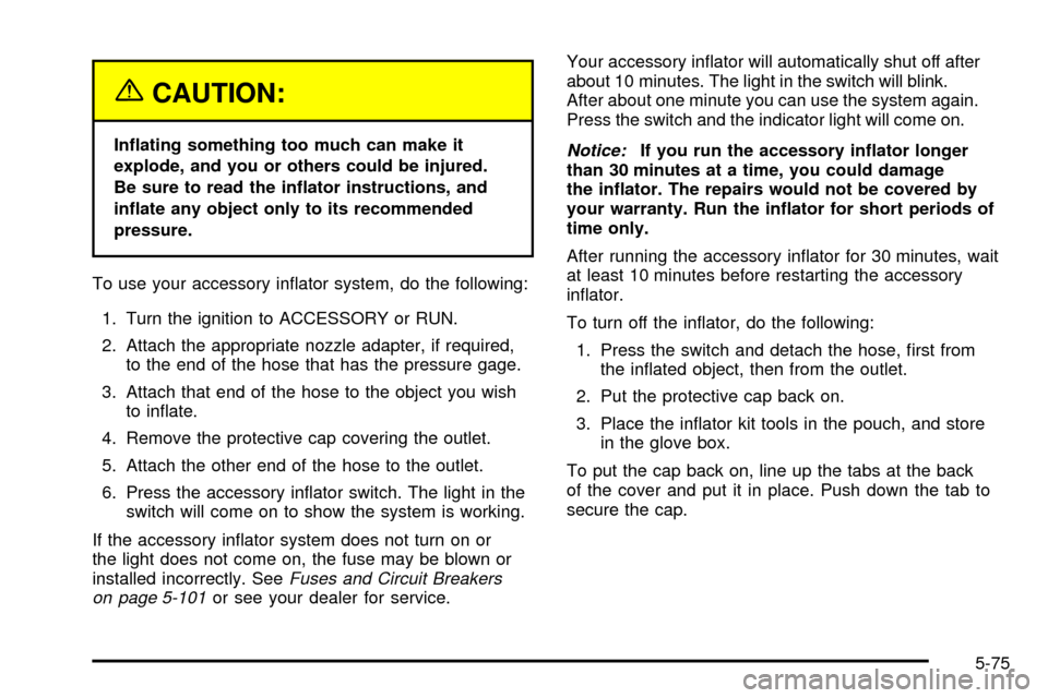
To use your accessory in¯ator system, do the following:
1. Turn the ignition to ACCESSORY or RUN.
2. Attach the appropriate nozzle adapter, if required,
to the end of the hose that has the pressure gage.
3. Attach that end of the hose to the object you wish
to in¯ate.
4. Remove the protective cap covering the outlet.
5. Attach the other end of the hose to the outlet.
6. Press the accessory in¯ator switch. The light in the
switch will come on to show the system is working.
If the accessory in¯ator system does not turn on or
the light does not come on, the fuse may be blown or
installed incorrectly. See
Fuses and Circuit Breakers
on page 5-101or see your dealer for service.Your accessory in¯ator will automatically shut off after
about 10 minutes. The light in the switch will blink.
After about one minute you can use the system again.
Press the switch and the indicator light will come on.
Notice:If you run the accessory in¯ator longer
than 30 minutes at a time, you could damage
the in¯ator. The repairs would not be covered by
your warranty. Run the in¯ator for short periods of
time only.
After running the accessory in¯ator for 30 minutes, wait
at least 10 minutes before restarting the accessory
in¯ator.
To turn off the in¯ator, do the following:
1. Press the switch and detach the hose, ®rst from
the in¯ated object, then from the outlet.
2. Put the protective cap back on.
3. Place the in¯ator kit tools in the pouch, and store
in the glove box.
To put the cap back on, line up the tabs at the back
of the cover and put it in place. Push down the tab to
secure the cap.
5-75
Page 404 of 462

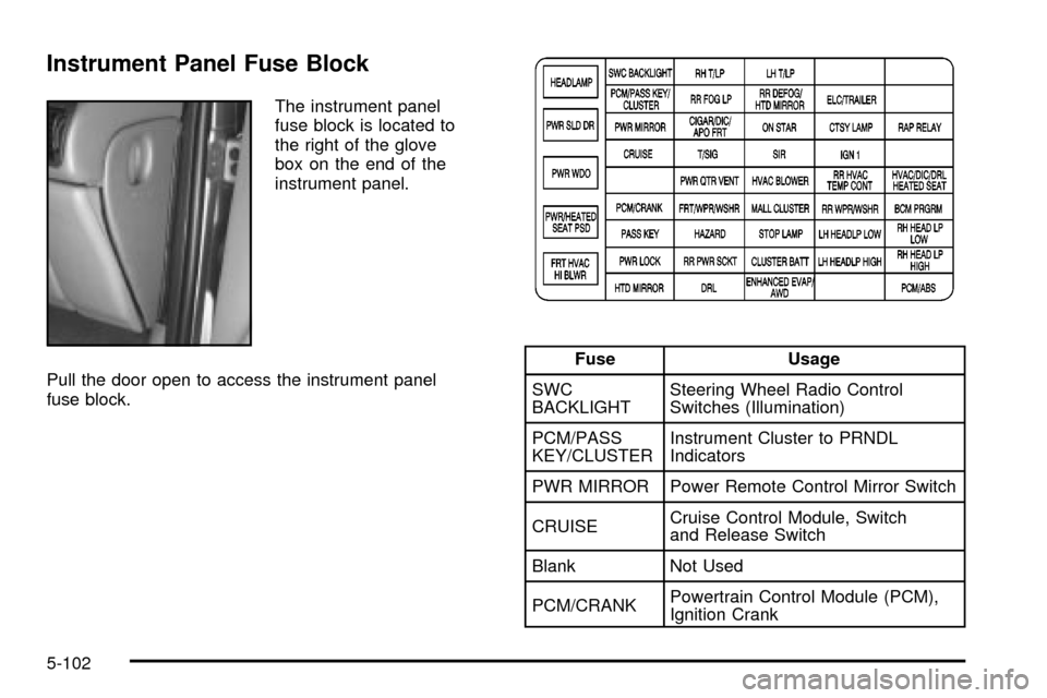
Instrument Panel Fuse Block
The instrument panel
fuse block is located to
the right of the glove
box on the end of the
instrument panel.
Pull the door open to access the instrument panel
fuse block.
Fuse Usage
SWC
BACKLIGHTSteering Wheel Radio Control
Switches (Illumination)
PCM/PASS
KEY/CLUSTERInstrument Cluster to PRNDL
Indicators
PWR MIRROR Power Remote Control Mirror Switch
CRUISECruise Control Module, Switch
and Release Switch
Blank Not Used
PCM/CRANKPowertrain Control Module (PCM),
Ignition Crank
5-102