OPEL 1900 1973 Service Manual
Manufacturer: OPEL, Model Year: 1973, Model line: 1900, Model: OPEL 1900 1973Pages: 625, PDF Size: 17.22 MB
Page 581 of 625
96-72 1973 OPEL SERVICE MANUALRUBBER
MALLET\
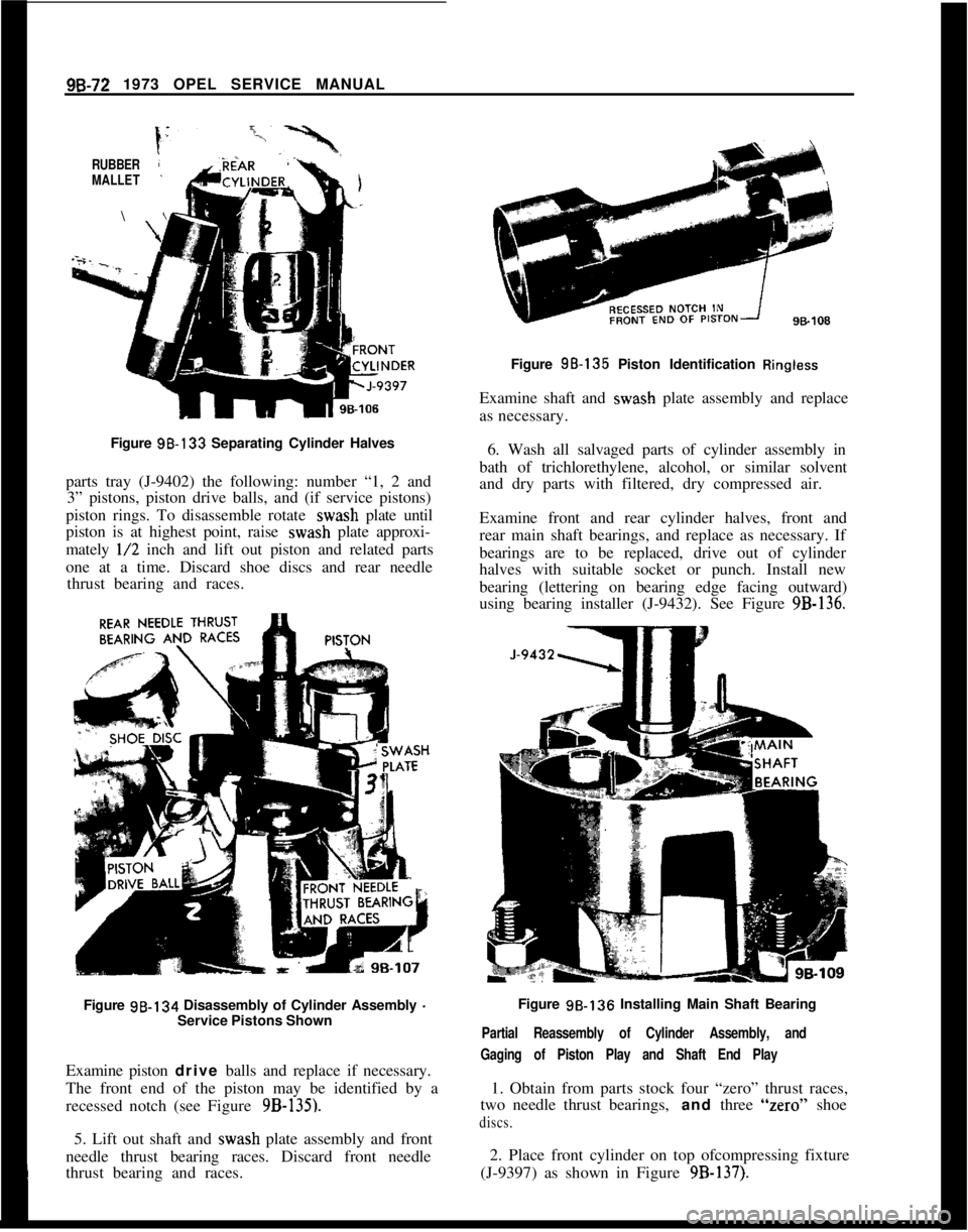
Figure 98-133 Separating Cylinder Halves
parts tray (J-9402) the following: number “1, 2 and
3” pistons, piston drive balls, and (if service pistons)
piston rings. To disassemble rotate wash plate until
piston is at highest point, raise wash plate approxi-
mately
l/2 inch and lift out piston and related parts
one at a time. Discard shoe discs and rear needle
thrust bearing and races.
Figure 98-134 Disassembly of Cylinder Assembly
-Service Pistons Shown
Examine piston drive balls and replace if necessary.
The front end of the piston may be identified by a
recessed notch (see Figure
9B-135).5. Lift out shaft and wash plate assembly and front
needle thrust bearing races. Discard front needle
thrust bearing and races.Figure 98-135 Piston Identification
RinglessExamine shaft and wash plate assembly and replace
as necessary.
6. Wash all salvaged parts of cylinder assembly in
bath of trichlorethylene, alcohol, or similar solvent
and dry parts with filtered, dry compressed air.
Examine front and rear cylinder halves, front and
rear main shaft bearings, and replace as necessary. If
bearings are to be replaced, drive out of cylinder
halves with suitable socket or punch. Install new
bearing (lettering on bearing edge facing outward)
using bearing installer (J-9432). See Figure
9B-136.Figure 98.136 Installing Main Shaft Bearing
Partial Reassembly of Cylinder Assembly, and
Gaging of Piston Play and Shaft End Play1. Obtain from parts stock four “zero” thrust races,
two needle thrust bearings, and three “zero” shoe
discs.2. Place front cylinder on top ofcompressing fixture
(J-9397) as shown in Figure
9B-137).
Page 582 of 625
REFRIGERANT COMPONENTS ALL MODELS9B- 73
F
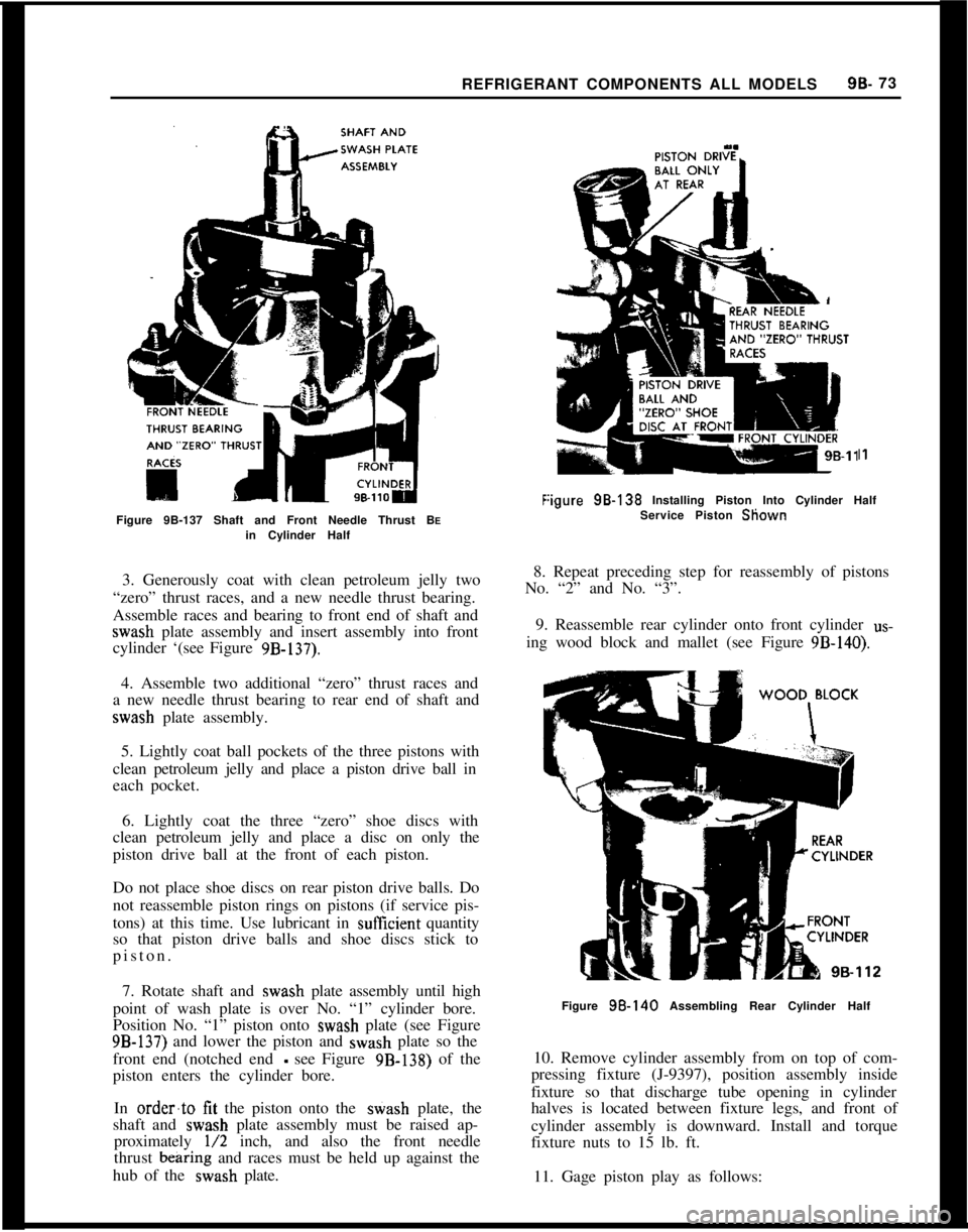
Figure 9B-137 Shaft and Front Needle Thrust BEin Cylinder Half
I1
:igure 98.138 Installing Piston Into Cylinder Half
Service Piston Sliown
3. Generously coat with clean petroleum jelly two
“zero” thrust races, and a new needle thrust bearing.
Assemble races and bearing to front end of shaft and
wash plate assembly and insert assembly into front
cylinder ‘(see Figure
9B-137).
8. Repeat preceding step for reassembly of pistons
No. “2” and No. “3”.
9. Reassemble rear cylinder onto front cylinder
us-
ing wood block and mallet (see Figure 9B-140).
4. Assemble two additional “zero” thrust races and
a new needle thrust bearing to rear end of shaft and
wash plate assembly.
5. Lightly coat ball pockets of the three pistons with
clean petroleum jelly and place a piston drive ball in
each pocket.
6. Lightly coat the three “zero” shoe discs with
clean petroleum jelly and place a disc on only the
piston drive ball at the front of each piston.
Do not place shoe discs on rear piston drive balls. Do
not reassemble piston rings on pistons (if service pis-
tons) at this time. Use lubricant in
sufEcient quantity
so that piston drive balls and shoe discs stick to
piston.
7. Rotate shaft and
wash plate assembly until high
point of wash plate is over No. “1” cylinder bore.
Position No. “1” piston onto
wash plate (see Figure
9B-137) and lower the piston and wash plate so the
front end (notched end
- see Figure 9B-138) of the
piston enters the cylinder bore.
In
order’to tit the piston onto the stiash plate, the
shaft and
wash plate assembly must be raised ap-
proximately
l/2 inch, and also the front needle
thrust
bearing and races must be held up against the
hub of the
wash plate.
Figure 98.140 Assembling Rear Cylinder Half
10. Remove cylinder assembly from on top of com-
pressing fixture (J-9397), position assembly inside
fixture so that discharge tube opening in cylinder
halves is located between fixture legs, and front of
cylinder assembly is downward. Install and torque
fixture nuts to 15 lb. ft.
11. Gage piston play as follows:
Page 583 of 625
98.74 1973 OPEL SERVICE MANUAL
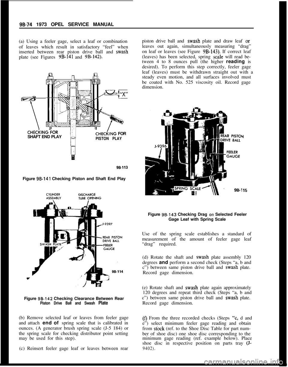
(a) Using a feeler gage, select a leaf or combination
of leaves which result in satisfactory “feel” when
inserted between rear piston drive ball and wash
plate (see Figures 9B-141 and 9B-142).CHECi(lNG?OR
SHAFT END PLAY
CHE&NG FOR
PISTON PLAY
98113Figure 98-141 Checking Piston and Shaft End Play
Figure 98-142 Checking Clearance Between Rear
Piston Drive Ball and Swash Plate(b) Remove selected leaf or leaves from feeler gage
and attach end of spring scale that is calibrated in
ounces. (A generator brush spring scale (J-5 184) or
the spring scale for checking distributor point setting
may be used for this step).
(c) Reinsert feeler gage leaf or leaves between rearpiston drive ball and wash plate and draw leaf or
leaves out again, simultaneously measuring “drag”
on leaf or leaves (see Figure
9B-143). If correct leaf
(leaves) has been selected, spring
:scale will read be-
tween 4 to 8 ounces pull (the higher reading is
desired). To perform this step correctly, feeler gage
leaf (leaves) must be withdrawn straight out with a
steady even motion, and all surfaces involved must
be coated with No. 525 viscosity oil. Record gage
dimension.
Y
i15Figure 98.143 Checking Drag
on Selected Feeler
Gage Leaf with Spring Scale
Use of the spring scale establishes a standard of
measurement of the amount of feeler gage leaf
“drag” required.
(d) Rotate the shaft and wash plate assembly 120
degrees and perform a second check (Steps “a, b and
c”) between same piston drive ball and wash plate.
Record gage dimension.
(e) Rotate shaft and wash plate again approximately
120 degrees and repeat third check (Steps “a, b and
c”) between same piston drive ball and wash plate.
Record gage dimension.(0 From the three recorded checks (Steps
“c, d and
e”) select minimum feeler gage reading and obtain
from
stock (ref. to the Shoe Disc Table for part num-
ber of shoe disc) one shoe disc corresponding to the
minimum gage reading (ref. example below). Place
shoe disc in respective position on parts tray
(J-
9402).
Page 584 of 625
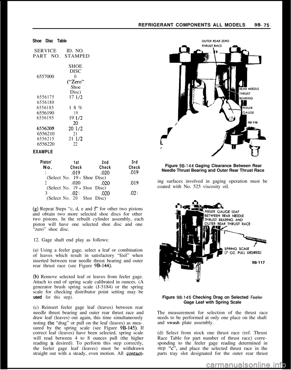
REFRIGERANT COMPONENTS ALL MODELS9B- 75Shoe Disc TableSERVICEID. NO.
PART NO. STAMPED
6557000
6556175
6556180
65561856556190
65561956556200
65562056556210
65562156556220
EXAMPLESHOE
DISC
0
(“ZSXO”Shoe
Disc)
17
l/218%
1919
l/2202&2
2121
l/2
22
Piston’
1st2nd3rdNo.
CheckCheckCheck
1,019,020,019(Select
No.19 -ShoeDisc)
2,020,020,019(Select
No.19-ShoeDisc)
3
.021,020.021(Select
No.20ShoeDisc)
(g) Repeat Steps “c, d, e and f’ for other two pistons
and obtain two more selected shoe discs for other
two pistons. In the rebuilt cylinder assembly, each
piston will have one selected shoe disc and one
“zero” shoe disc.
12. Gage shaft end play as follows:
(a) Using a feeler gage, select a leaf or combination
of leaves which result in satisfactory “feel” when
inserted between rear needle thrust bearing and outer
rear thrust race (see Figure
9B-144).
(b) Remove selected leaf or leaves from feeler gage.
Attach to end of spring scale calibrated in ounces. (A
generator brush spring scale (J-5184) or the spring
scale for checking distributor point setting may be
used for this step).(c) Reinsert feeler gage leaf (leaves) between rear
needle thrust bearing and outer rear thrust race and
draw leaf (leaves) out again, this time simultaneously
noting the “drag” or pull on the leaf (leaves) as mea-
sured by the spring scale (see Figure
9B-145). If
correct leaf (leaves) have been selected, spring scale
will read between 4 to 8 ounces pull (the higher
reading is desired). To perform this step correctly,
the feeler gage leaf (leaves) must be withdrawn
straight out with a steady, even motion. All contact-Figure 98.144 Gaging Clearance Between Rear
Needle Thrust Bearing and Outer Rear Thrust Race
ing surfaces involved in gaging operation must be
coated with No. 525 viscosity oil.
Figure 98.145 Checking Drag on Selected
FeeletGage Leaf with Spring Scale
The measurement for selection of the thrust race
needs to be performed at only one place on the shaft
and wash plate assembly.
(d) Select from stock one thrust race (ref. Thrust
Race Table for part number of thrust race) corre-
sponding to the feeler gage reading determined in
step
“C”,and place the selected thrust race in the
parts tray slot designated for the outer rear thrust
Page 585 of 625
9B-76 1973 OPEL SERVICE MANUAL
race. If, for example a feeler gage reading of 0.009
inch results, a thrust race with a number “9”,
stamped on it should be selected.Thrust Race TableSERVICEID NO.THICK-
PART NO. ON RACE
NESS
6556000
0.0920
6556050
5.09656556055
5l/2.09706556060
6.0975
65560656
l/2.09806556070
7.0985
6556075
7l/2.09906556080
8.0995
6556085
8l/2.lOOO6556090
T/2,100s
65560959.lOlO
655610010,101s
655610510 l/2.10206556110
.10256556115
11111/2.10306556120
12.1035The selected thrust race will replace only the “zero”
outer rear thrust race. The remaining three “zero”
thrust races will remain as part of the cylinder assem-
bly.
13. Remove cylinder assembly from inside compress-
ing fixture (J-9397), place on top of compressing
fixture (see Figure 9B-133) and disassemble rear cyl-
inder from front cylinder using rubber mallet or
hammer and wood block.
14. Carefully disassemble one piston at a time from
front cylinder and lay piston, front and rear piston
drive balls and front “zero” shoe disc in respective
slot of parts tray (J-9402). To disassemble, rotatewash plate until piston is at highest point, raise awash plate approximately
l/2 inch and lift out pis-
ton and related parts, one at a time.
15. Remove outer rear ‘?ero” thrust race from shaft
and set it aside for future gaging procedures.
16. Remove previously selected outer rear thrust
race from parts tray, lightly coat with clear pe-
troleum jelly and assemble onto shaft.
Final Reassembly of Cylinder Assembly1. Reassemble piston rings (if service pistons) onto
pistons (ring scraper groove toward center of piston)
and rotate ring so that break or gap in ring can be
squeezed together when piston is being inserted into
cylinder bore.
2. Reassemble piston drive balls, “zero” and se-lected shoe discs onto No. “1” piston, and apply
clear petroleum jelly to piston pockets and shoe discs
so that balls and discs stick to piston. BE SURE to
reassemble balls and shoe discs into their specific
positions on front and rear of piston.
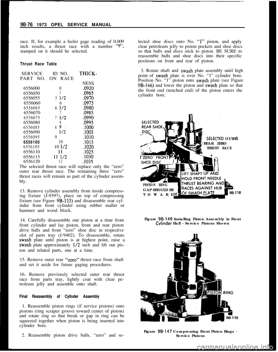
3. Rotate shaft and wash plate assembly until high
point of wash plate is over No. “1” cylinder bore.
Position No. “1” piston onto wash plate (see Figure9B-146) and lower the piston and wash plate so that
the front end (notched end) of the piston enters the
cylinder bore.XTED OUTER
/REAR ZERO
THRUST RACE
PISTON RINGGAP SHOULD BE
TOWARD
98-118Figure 98.146 Installing Piston Assembly in Front
Cvlinder Half - Service Pistons Shown
Figure 98.147 Compressing Front Piston Rings
-Service Pistons
Page 586 of 625
REFRIGERANT COMPONENTS ALL MODELS99.77
In order to tit the piston onto the wash plate and
into the cylinder bore, the wash plate must be raised
approximately l/2 inch, the front needle thrust bear-
ing and races must be held up against the hub of thewash plate, and the service piston rings must be
squeezed together (see Figure
9B-147). Lubricate
cylinder bore, piston assembly and wash plate with
No. 525 viscosity oil to facilitate reassembly.
4. Repeat procedure in Steps 1 and 2 for installation
of No. 2 and No. 3 pistons.
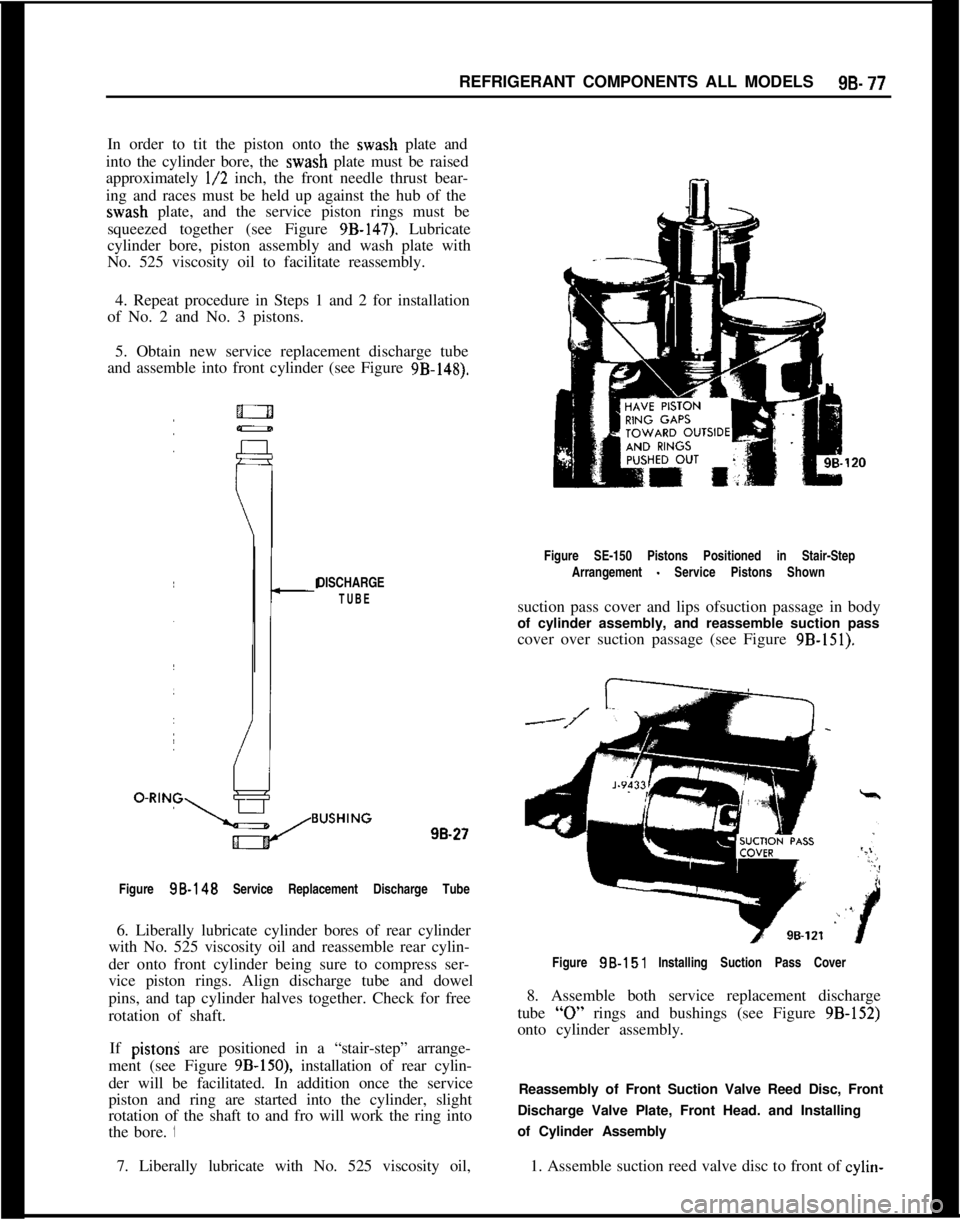
5. Obtain new service replacement discharge tube
and assemble into front cylinder (see Figure
9B-148).Figure SE-150 Pistons Positioned in Stair-Step
DISCHARGE
TUBEArrangement
- Service Pistons Shown
suction pass cover and lips ofsuction passage in body
of cylinder assembly, and reassemble suction pass
cover over suction passage (see Figure
9B-151).98.27
Figure
SB-148 Service Replacement Discharge Tube
6. Liberally lubricate cylinder bores of rear cylinder
with No. 525 viscosity oil and reassemble rear cylin-
der onto front cylinder being sure to compress ser-
vice piston rings. Align discharge tube and dowel
pins, and tap cylinder halves together. Check for free
rotation of shaft.
If pistoni are positioned in a “stair-step” arrange-
ment (see Figure
9B-150), installation of rear cylin-
der will be facilitated. In addition once the service
piston and ring are started into the cylinder, slight
rotation of the shaft to and fro will work the ring into
the bore. ‘IFigure
98.151 Installing Suction Pass Cover
8. Assemble both service replacement discharge
tube
“0” rings and bushings (see Figure 9B-152)
onto cylinder assembly.
Reassembly of Front Suction Valve Reed Disc, Front
Discharge Valve Plate, Front Head. and Installing
of Cylinder Assembly
7. Liberally lubricate with No. 525 viscosity oil,1. Assemble suction reed valve disc to front of cylin-
Page 587 of 625
98-78 1973 OPEL SERVICE MANUAL
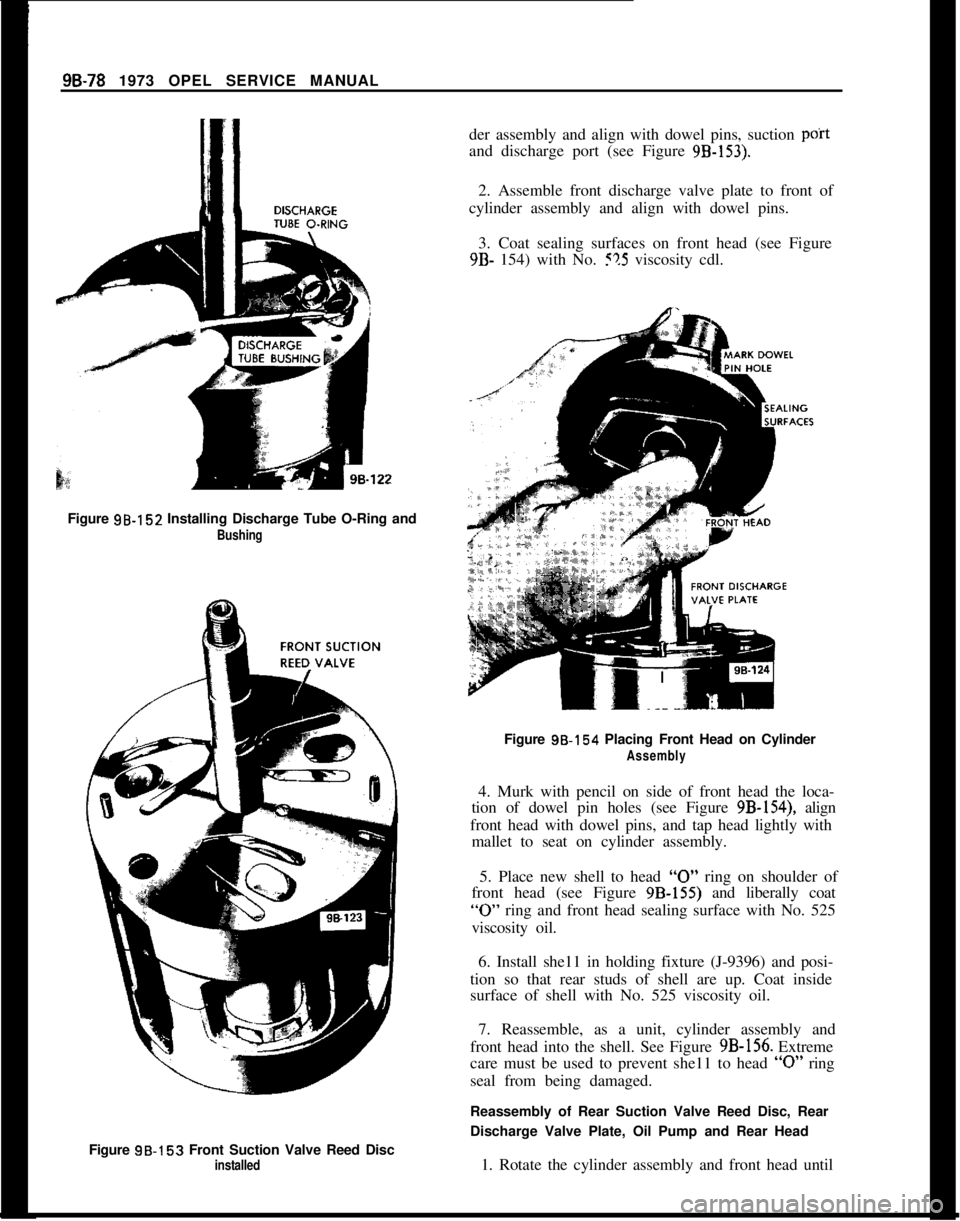
der assembly and align with dowel pins, suction poitand discharge port (see Figure
9B-153).2. Assemble front discharge valve plate to front of
cylinder assembly and align with dowel pins.
3. Coat sealing surfaces on front head (see Figure9B- 154) with No. !?5 viscosity cdl.
Figure 98.152 Installing Discharge Tube O-Ring and
BushingFigure 98.154 Placing Front Head on Cylinder
Assembly4. Murk with pencil on side of front head the loca-
tion of dowel pin holes (see Figure 9B-154), align
front head with dowel pins, and tap head lightly with
mallet to seat on cylinder assembly.
5. Place new shell to head
“0” ring on shoulder of
front head (see Figure 9B-155) and liberally coat
“0” ring and front head sealing surface with No. 525
viscosity oil.
6. Install she11 in holding fixture (J-9396) and posi-
tion so that rear studs of shell are up. Coat inside
surface of shell with No. 525 viscosity oil.
Figure 9B-153 Front Suction Valve Reed Disc
installed7. Reassemble, as a unit, cylinder assembly and
front head into the shell. See Figure 9B-156. Extreme
care must be used to prevent she11 to head
“0” ring
seal from being damaged.
Reassembly of Rear Suction Valve Reed Disc, Rear
Discharge Valve Plate, Oil Pump and Rear Head
1. Rotate the cylinder assembly and front head until
Page 588 of 625
REFRIGERANT COMPONENTS ALL MODELS9B- 79
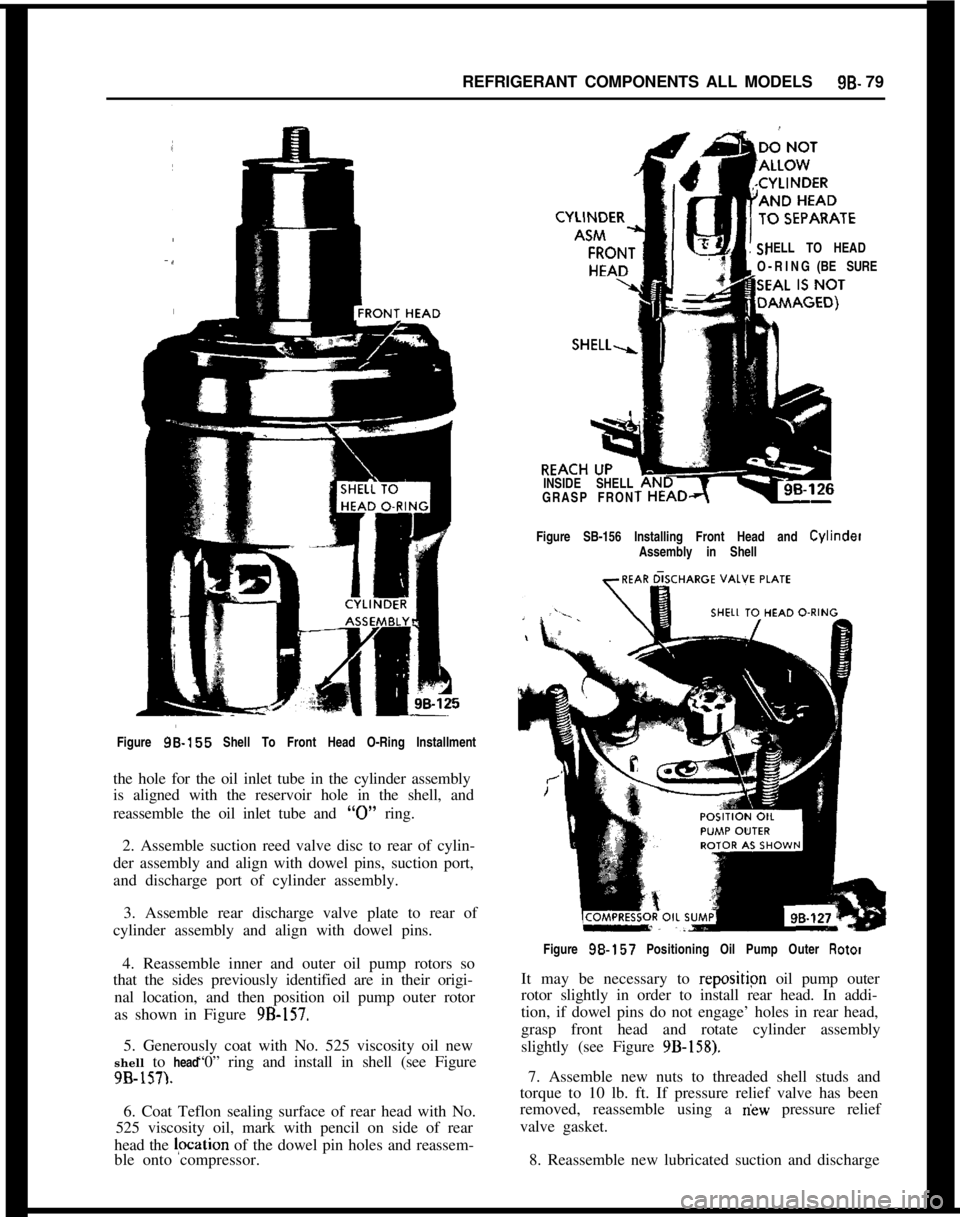
HELL TO HEAD
O-RING(BE SURE
INSIDE SHELL
GRASP FRON
Figure SB-156 Installing Front Head and Cylinder
Assembly in Shell
Figure
96-155 Shell To Front Head O-Ring Installment
the hole for the oil inlet tube in the cylinder assembly
is aligned with the reservoir hole in the shell, and
reassemble the oil inlet tube and
“0” ring.
2. Assemble suction reed valve disc to rear of cylin-
der assembly and align with dowel pins, suction port,
and discharge port of cylinder assembly.
3. Assemble rear discharge valve plate to rear of
cylinder assembly and align with dowel pins.
4. Reassemble inner and outer oil pump rotors so
that the sides previously identified are in their origi-
nal location, and then position oil pump outer rotor
as shown in Figure
9B-157.5. Generously coat with No. 525 viscosity oil new
“0” ring and install in shell (see Figure shell to head
9B-157).6. Coat Teflon sealing surface of rear head with No.
525 viscosity oil, mark with pencil on side of rear
head the lpcation of the dowel pin holes and reassem-
ble onto compressor.Figure
98.157 Positioning Oil Pump Outer Rotor
It may be necessary to repositipn oil pump outer
rotor slightly in order to install rear head. In addi-
tion, if dowel pins do not engage’ holes in rear head,
grasp front head and rotate cylinder assembly
slightly (see Figure
9B-158).7. Assemble new nuts to threaded shell studs and
torque to 10 lb. ft. If pressure relief valve has been
removed, reassemble using a
riew pressure relief
valve gasket.
8. Reassemble new lubricated suction and discharge
Page 589 of 625

96-80 1973 OPEL SERVICE MANUAL
LINE UP LOCA
PINS AND
HOFigure SB-158 Installing Rear Head
“0” rings into suction and discharge ports of rear
head.9. Reassemble shaft seal onto front of shaft andwash plate assembly. Do not reassemble clutch
drive plate at this time.
Leak ‘Testing Compressor1. After the shaft seal pressure test has been per-
formed, change the test circuit to the configuration
shown in Figure 9B-160.
2. With hose attached only to high pressure side of
Leak Test Fixture J-9625, open high pressure valve
to charge high pressure side of compressor. As soon
as high pressure gage stabilizes reading, close valve.
If high pressure gage drops back immedaitely when
valve is closed, an internal leak is indicated. Correct
leak as necessary.
If an internal leak is indicated, the leak may exist
about the head sealing surface or Teflon seal,
dis-
charg,e tube, shell to head “0” rings, or suction valve
reed discs.
3. Remove drain screw from shell and add No. 525
viscosity oil as specified.
4.
R~eassemble pulley assembly, and coil and hous-
ing assembly onto hub of front head.
5. Complete reassembly by installing clutch drive
plate onto hub of front head. See Figure 9B-164
disassembled view of compressor.
Page 590 of 625
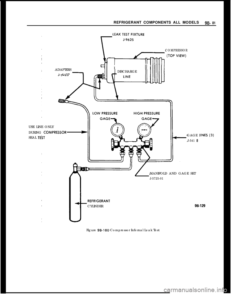
REFRIGERANT COMPONENTS ALL MODELS9B- 81ADAPTERS
91 I
I -.n” 1-“II III I
DISCHARGE11 1
COMPRESSORUSE LINE ONLY
DURING
COMPRESSOR-SEAL
T&TGAGE IJ-541 6MANIFOLD AND GAGE SET
J-5725-01REFRIGERANl
CYLINDER
99.129Figure 96-160 Compressor Infernal Leak Test