spare wheel OPEL 1900 1973 Service Manual
[x] Cancel search | Manufacturer: OPEL, Model Year: 1973, Model line: 1900, Model: OPEL 1900 1973Pages: 625, PDF Size: 17.22 MB
Page 67 of 625

1F. 46 1973 OPEL SERVICE MANUAL
’
/
Headlight High-Low Beam Control and Passing:
SignalI
When the headlights have been switched on, high
and low beam selection is made by raising the direc-
tional signal lever toward steering wheel. Each
ti&the lever is raised, beam position, will change.
When the headlights are not on, a flashing headlight
signal may be given by raising and lotiering the di-
rectional signal lever. With the headlights on and
inlow beam position, raising and lowering the direc-
tional signal lever will also cause the headlights to
flash.
Fog Light SwitchAll Rallye models are equipped with two white f?g
lights mounted below the front bumper.
The fog light toggle switch is located on the
insty-ment cluster to the left of the temperature and
fuelgauge cluster.
/
The fog lights can be turned off at any time by the
toggle switch, but can only be tyrned on when: :
1. The ignition switch on or the
?gine running.!
2. The fog light toggle switch lower half is pushed
in.3. The parking lights and/or low beam headlights
are
OKThe fog lights are automatically turned off if the
ignition switch is on and the headlights are switched
to high beam position.
Courtesy LightThe courtesy light illuminates the interior of the Car
when any door is opened. The courtesy light can also
be turned on with all doors closed by tilting the l&s.
GT Headlamp MechanismThe concealed headlamps are moved mechanically.
Pushing actuating lever on left side of console opens
headlamps and pulling lever closes headlamps. Two
(2) meshing gear segments convert the movement, of
the lever to a rotation of 180 degrees. The pivots of
the headlamps lie below the centerline so that with
headlamps in closed position, the headlamp housing
is flush with front sheet metal. Refer to Group 110,
Section “F”, for service procedures on the GT head-
lamp mechanism.
A white indicator lamp in the instrument panel lights
if the headlamps are not completely opened lorclosed The switches of the headlamp electrical sys-
tem are located behind the left headlamp operating,
mechanism.
MAINTENANCE AND ADJUSTMENTSHEADLAMP AIMING
The headlamps must be properly aimed in order to
obtain maximum road illumination and safety that
has been built into the headlighting equipment. With
the Guide T-3 type sealed beam units, proper aiming
is even more important because the increased range
and power of this lamp make even slight variations
from recommended aiming hazardous to approach-
ing motorists. The headlamps must be checked for
proper aim whenever a sealed beam unit is replaced
and after an adjustment or repairs of the front end
sheet metal assembly.
Regardless of method used for checking headlamp
aim, car must be at normal weight, that is, with gas,
oil, water, and spare tire. Tires must be uniformly
inflated to specified pressure. If car will regularly
carry an unusual load in rear compartment, or a
trailer, these loads should be on car when headlamps
are checked. Some States have special requirements
for headlamp aiming adjustment, and these require-
ments should be known and observed.
Horizontal and vertical aiming of each seal beam
unit is provided by two adjusting screws which move
the mounting ring in the body against the tension of
the coil spring. There is no adjustment for focus,
since the sealed beam unit is set for proper focus
during manufacturing assembly.
MAJOR REPAIRHEADLIGHT SWITCH
- OPEL 1900. MANTA
Removal1. Remove instrument cluster cover panel. See Sec-
tion H.
2. Compress retaining springs and pull switch out.
See Figure 1 F-
1.3. Pull multiple socket off switch.
Installation
1: Plug multiple socket in switch and push switch in
panel until clips lock in place.
2. Replace instrument cover and secure with two (2)
screws.
Page 330 of 625

FUEL SYSTEMSC- 39
MAJOR REPAIR
FUEL TANK OPEL 1900 AND MANTAThe fuel tank is located below the luggage compart-
ment floor panel and is attached with a strap.
The plastic tank vent hoses join in a connector from
where the fuel vapors escape through a fourth
ho%attached to the upper flange of the tank.
On all vehicles, the vent hose is connected to an
activated carbon container mounted to the front
wheel house panel.
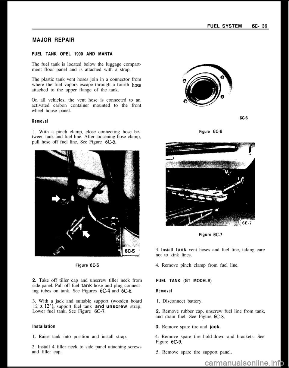
Removal1. With a pinch clamp, close connecting hose be-
tween tank and fuel line. After loosening hose clamp,
pull hose off fuel line. See Figure
6C-5.Figure
6C-52. Take off tiller cap and unscrew tiller neck from
side panel. Pull off fuel tank hose and plug connect-
ing tubes on tank. See Figures 6C-4 and
6C-6.3. With a jack and suitable support (wooden board
12
x 12”), support fuel tank and unscrew strap.
Lower fuel tank. See Figure
6C-7.
Installation1. Raise tank into position and install strap.
2. Install 4 filler neck to side panel attaching screws
and filler cap.Figure
K-6Figure
6C-73. Install tank vent hoses and fuel line, taking care
not to kink lines.
4. Remove pinch clamp from fuel line.
FUEL TANK (GT MODELS)
Removal1. Disconnect battery.
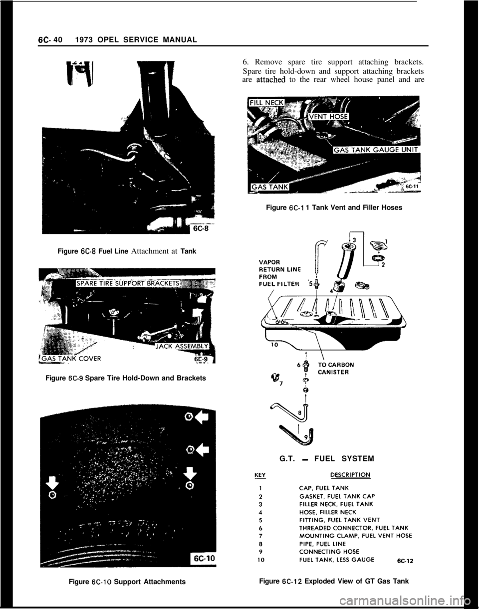
2. Remove rubber cap, unscrew fuel line from tank,
and drain fuel. See Figure
6C-8.3. Remove spare tire and jack.
4. Remove spare tire hold-down and brackets. See
Figure
6C-9.5. Remove spare tire support panel.
Page 331 of 625

6C- 401973 OPEL SERVICE MANUAL
Figure K-8 Fuel Line Attachment at Tank6. Remove spare tire support attaching brackets.
Spare tire hold-down and support attaching brackets
are
;attached to the rear wheel house panel and are
Figure
6C-1 1 Tank Vent and Filler Hoses
Figure
6C-9 Spare Tire Hold-Down and Brackets
G.T.
- FUEL SYSTEM
Figure
612-10 Support AttachmentsFigure 6C-12 Exploded View of GT Gas Tank