ECU OPEL AMPERA E 2017.5 Manual user
[x] Cancel search | Manufacturer: OPEL, Model Year: 2017.5, Model line: AMPERA E, Model: OPEL AMPERA E 2017.5Pages: 265, PDF Size: 6.24 MB
Page 66 of 265

64Storage9Warning
Always make sure that the load in
the vehicle is securely stowed.
Otherwise objects can be thrown
around inside the vehicle and
cause personal injury or damage
to the load or car.
‚óŹ The payload is the difference between the permitted gross
vehicle weight (see identification
plate 3 246) and the EC kerb
weight.
The EC kerb weight includes
weights for the driver (68 kg),
luggage (7 kg) and all fluids.
Optional equipment and
accessories increase the kerb
weight.
‚óŹ Driving with a roof load increases
the sensitivity of the vehicle to
cross-winds and has a
detrimental effect on vehicle
handling due to the vehicle's
higher centre of gravity.
Distribute the load evenly and secure it properly with retaining
straps. Adjust the tyre pressure
and vehicle speed according to
the load conditions. Check and
retighten the straps frequently.
Do not drive faster than
120 km/h.
The permissible roof load is
50 kg. The roof load is the
combined weight of the roof rack and the load.
Page 100 of 265

98Instruments and controlsTo look at the information in greater
detail, select the link within the email
and log in to your account.
Destination download
A desired destination can be directly
downloaded to the navigation system.
Press Z to call an advisor and
describe the destination or point of
interest.
The advisor can look up any address or point of interest and directly send
the destination to the built-in
navigation system.
OnStar settings
OnStar PIN
To have full access to all OnStar
services, a four-digit PIN is required. The PIN has to be personalised when first talking to an advisor.
To change the PIN, press Z to call an
advisor.Account data
An OnStar subscriber has an account where all the data is stored. To
request a change of the account
information, press Z and talk to an
advisor or log in to your account.
If the OnStar service is used on
another vehicle, press Z and request
that the account be transferred to the new vehicle.
Note
In any case, if the vehicle is disposed
of, sold or otherwise transferred,
immediately inform OnStar about
the changes and terminate the
OnStar service on this vehicle.
Vehicle location
The vehicle location is transmitted to OnStar when service is requested or triggered. A message on the Infodisplay informs about this
transmission.
To activate or deactivate the
transmission of the vehicle location,
press and hold j until an audio
message is heard.The deactivation is indicated by the
status light flashing red and green for a short period of time and each time
the vehicle is started.
Note
If the transmission of the vehicle
location is deactivated, some
services are no longer available.
Note
The vehicle location always remains
accessible to OnStar in the case of
an emergency.
Find the privacy policy in your
account.
Software updates
OnStar may remotely carry out software updates without further
notice or consent. These updates are to enhance or maintain safety and
security or the operation of the
vehicle.
These updates may concern privacy
issues. Find the privacy policy in your
account.
Page 109 of 265

Infotainment system107The well-thought-out design of the
control elements, the touch screen and the clear displays enable you to
control the system easily and
intuitively.
Note
This manual describes all options
and features available for the
various Infotainment systems.
Certain descriptions, including those
for display and menu functions, may
not apply to your vehicle due to
model variant, country
specifications, special equipment or
accessories.
Important information on
operation and traffic safety9 Warning
The Infotainment system must be
used so that the vehicle can be
driven safely at all times. If in
doubt, stop the vehicle and
operate the Infotainment system
while the vehicle is stationary.
Radio reception
Radio reception may be disrupted by
static, noise, distortion or loss of
reception due to:
‚óŹ changes in distance from the transmitter
‚óŹ multipath reception due to reflection
‚óŹ shadowing
Theft-deterrent feature The Infotainment system is equipped
with an electronic security system for the purpose of theft deterrence.
The Infotainment system therefore
functions only in your vehicle and is
worthless to a thief.
Page 121 of 265

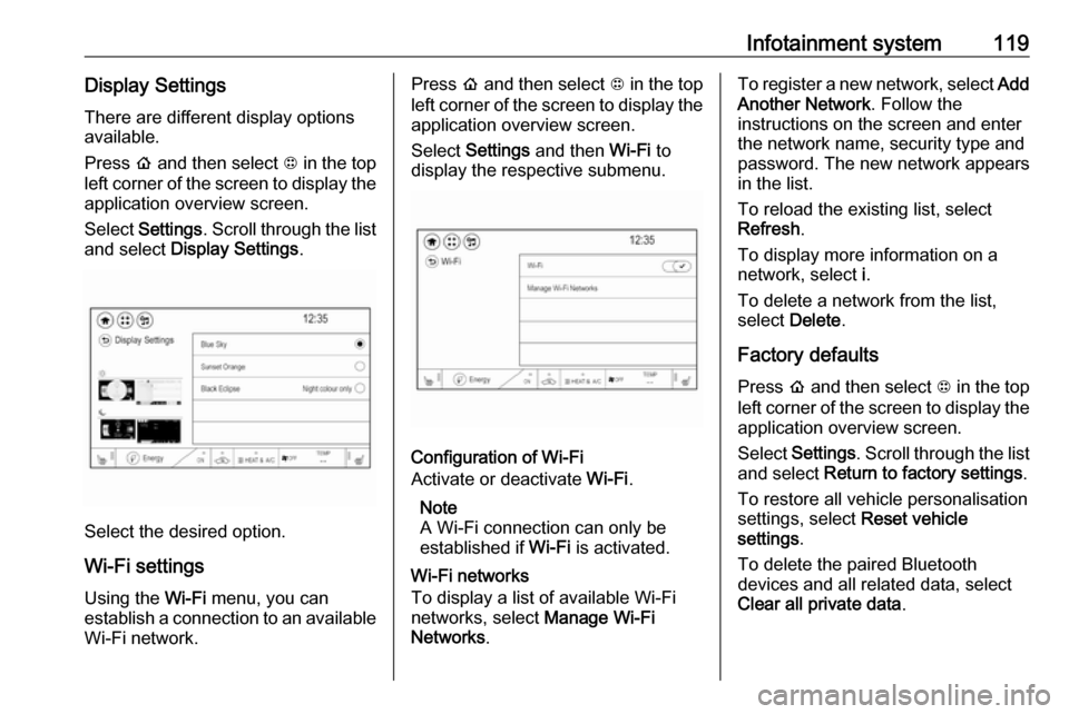
Infotainment system119Display SettingsThere are different display options
available.
Press p and then select 1 in the top
left corner of the screen to display the application overview screen.
Select Settings . Scroll through the list
and select Display Settings .
Select the desired option.
Wi-Fi settings Using the Wi-Fi menu, you can
establish a connection to an available
Wi-Fi network.
Press p and then select 1 in the top
left corner of the screen to display the application overview screen.
Select Settings and then Wi-Fi to
display the respective submenu.
Configuration of Wi-Fi
Activate or deactivate Wi-Fi.
Note
A Wi-Fi connection can only be
established if Wi-Fi is activated.
Wi-Fi networks
To display a list of available Wi-Fi
networks, select Manage Wi-Fi
Networks .
To register a new network, select Add
Another Network . Follow the
instructions on the screen and enter
the network name, security type and
password. The new network appears
in the list.
To reload the existing list, select
Refresh .
To display more information on a
network, select i.
To delete a network from the list,
select Delete .
Factory defaults Press p and then select 1 in the top
left corner of the screen to display the application overview screen.
Select Settings . Scroll through the list
and select Return to factory settings .
To restore all vehicle personalisation
settings, select Reset vehicle
settings .
To delete the paired Bluetooth
devices and all related data, select
Clear all private data .
Page 157 of 265

Driving and operating155Electric drive unit
Operation
The vehicle uses an electric drive
unit. The shift lever is located on the
console between the seats.P:park position, wheels are locked, engage only when the vehicle is
stationaryR:reverse gear, engage only when
the vehicle is stationaryN:neutralD:drive mode, low recuperationL:low, high recuperation, enables
one pedal driveThe shift lever always starts from a
centre position. A yellow dot is
displayed on the shift pattern. After
releasing the shift lever, it will return
to the centre position.
P : This position locks the front
wheels. It is the recommended
position when starting the propulsion system because the vehicle cannot
move easily.9 Warning
It is dangerous to get out of the
vehicle if the shift lever is not fully
in P with the parking brake firmly
applied. The vehicle can roll.
Do not leave the vehicle when the propulsion system is running, the
vehicle may move suddenly. You
or others can be injured. To be
sure the vehicle will not move,
even if you are on even ground,
always apply the parking brake
and move the shift lever to P.The shift lock release button is
designed to prevent inadvertent
shifting out of P unless the vehicle has
been started, the brake pedal is
applied, and the shift lock release
button is pressed.
When the vehicle is stopped, press POWER m to switch off the vehicle.
The electric drive unit will shift to P
automatically.
The vehicle will not shift to P if it is
moving too fast. Stop the vehicle and
shift to P.
To shift in and out of P, press the
release button.
R : Use this gear to reverse.
Page 203 of 265

Driving and operating2013.Touch + or ‚ąí to change the month
and day for the start of Winter.
4. Touch q to exit the screen.Electric rate schedule editing
Electric rate information from the
utility company for the charging
location is required.
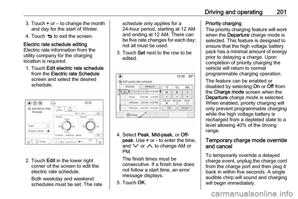
1. Touch Edit electric rate schedule
from the Electric rate Schedule
screen and select the desired
schedule.
2. Touch Edit in the lower right
corner of the screen to edit the
electric rate schedule.
Both weekday and weekend
schedules must be set. The rate
schedule only applies for a
24-hour period, starting at 12 AM
and ending at 12 AM. There can
be five rate changes for each day; not all must be used.
3. Touch Set next to the row to be
edited.
4. Select Peak, Mid-peak , or Off-
peak . Use + or - to enter the time,
and o or n to change AM or
PM.
The finish times must be
consecutive. If a finish time does not follow a start time, an error
message displays.
5. Touch OK.
Priority charging
The priority charging feature will work
when the Departure charge mode is
selected. This feature is designed to ensure that the high voltage battery
pack has a minimal amount of energy prior to delaying a charge. Uponcompletion of priority charging the
vehicle will return to normal
programmable charging operation.
The feature can be enabled or
disabled by selecting On or Off from
the Charge mode screen when the
Departure charge mode is selected.
When enabled, priority charging will
only prevent programmable charging
while the high voltage battery is
recharged from a depleted state to a
level allowing 40% of the driving
range.
Temporary charge mode override
and cancel
To temporarily override a delayed
charge event, unplug the charge cord
from the charge port and then plug it
back in within five seconds. A single
audible chirp will sound and charging
will begin immediately.
Page 210 of 265

208Driving and operatingNote
By choosing a reduced charge level,
the charging time is increased.
Charge limit selection can be made
using the Charge limit preference
screen on the Info display. Charge limit selection 3 197.
Grounding instructions This product must be grounded. If thisproduct should malfunction or break
down, grounding provides a path of
least resistance for electric current to
reduce the risk of electric shock. This
product is equipped with a cord that
has an equipment grounding
conductor and a grounding plug. The plug must be plugged into an
appropriate outlet that is properly
installed and grounded in accordance with all local codes and ordinances.9 Warning
Improper connection of the charge
cord ground may cause electrical
shock. Check with a qualified
electrician if there is doubt as to
whether the charge circuit is
properly grounded. Do not modify
the plug provided with the product.
If it will not fit the electrical outlet,
have a proper electrical outlet
installed by a qualified electrician.
Charge cord mounting
instructions
Choose an appropriate, solid location for mounting the charge cord. The
appropriate height for mounting the
charge cord is 91 cm from the floor.
Space the holes 18.7 cm apart.
Install the mounting screws leaving
the head of the screws 5 mm from the
surface.
Securely mount the charge cord on to
the screws.
Connect the wall plug to the electrical
outlet.
Connect the vehicle plug to the
charge port.
Electrical requirementsCaution
Do not use portable or stationary
backup generating equipment to charge the vehicle. This may
cause damage to the vehicle's
charging system. Only charge the
vehicle from utility supplied power.
Charge limit selection 3 197.
Reduced limit mode allows a non-
dedicated circuit to be used but
increases the charging time.
This vehicle is capable of being
charged with standard vehicle
charging equipment complying with
one or more of the following
standards:
‚óŹ SAE J1772
‚óŹ SAE J2847‚Äď2
‚óŹ IEC 61851-1
‚óŹ IEC 61851-22
‚óŹ IEC 61851-23
‚óŹ IEC 61851-24
‚óŹ IEC 62196-1
Page 216 of 265

214Vehicle care
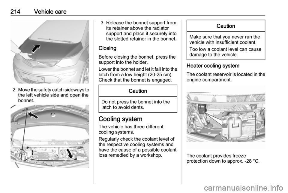
2.Move the safety catch sideways to
the left vehicle side and open the
bonnet.
3. Release the bonnet support from its retainer above the radiator
support and place it securely into
the slotted retainer in the bonnet.
Closing Before closing the bonnet, press the
support into the holder.
Lower the bonnet and let it fall into the latch from a low height (20-25 cm).
Check that the bonnet is engaged.Caution
Do not press the bonnet into the
latch to avoid dents.
Cooling system
The vehicle has three different
cooling systems.
Regularly check the coolant level of
the respective cooling systems and
have the cause of a possible coolant
loss remedied by a workshop.
Caution
Make sure that you never run the
vehicle with insufficient coolant.
Too low a coolant level can cause damage to the vehicle.
Heater cooling system
The coolant reservoir is located in the engine compartment.
The coolant provides freeze
protection down to approx. -28 ¬įC.
Page 221 of 265

Vehicle care219‚óŹ See the Owner's Manual forfurther information.
‚óŹ Explosive gas may be present in the vicinity of the vehicle battery.
Post-crash label
The post-crash label is located in the
door frame 3 152.
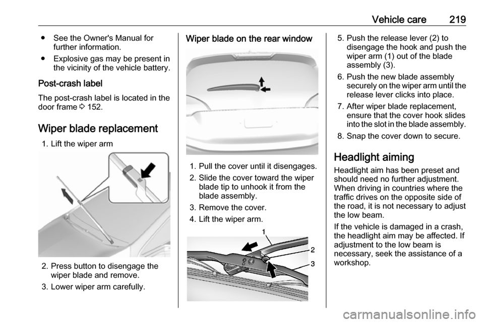
Wiper blade replacement 1. Lift the wiper arm
2. Press button to disengage the wiper blade and remove.
3. Lower wiper arm carefully.
Wiper blade on the rear window
1. Pull the cover until it disengages.
2. Slide the cover toward the wiper blade tip to unhook it from the
blade assembly.
3. Remove the cover.
4. Lift the wiper arm.
5. Push the release lever (2) to disengage the hook and push the
wiper arm (1) out of the blade
assembly (3).
6. Push the new blade assembly securely on the wiper arm until the
release lever clicks into place.
7. After wiper blade replacement, ensure that the cover hook slides
into the slot in the blade assembly.
8. Snap the cover down to secure.
Headlight aiming Headlight aim has been preset and
should need no further adjustment.
When driving in countries where the
traffic drives on the opposite side of the road, it is not necessary to adjust
the low beam.
If the vehicle is damaged in a crash,
the headlight aim may be affected. If
adjustment to the low beam is
necessary, seek the assistance of a
workshop.
Page 228 of 265

226Vehicle careNumberUsage1‚Äď2Power window rear3‚Äď4Rechargeable energy
storage system 15‚Äď6‚Äď7Left high‚Äźbeam headlight8Right high‚Äźbeam headlight9Left low‚Äźbeam headlight10Right low‚Äźbeam headlight11Horn12‚Äď13Front wiper motor driver14Tailgate15Front wiper motor co-driver16Electronic brake control
module supply electronicsNumberUsage17Rear wiper18Tailgate19Seat module front20Washer21HID light22Linear power module23Electronic brake control
module supply motor24Seat module rear25Powertrain26Transmission range control
module27Aero shutter28Auxiliary oil pump29E-booster motor source30Front power windows31In-panel bussed electrical
centreNumberUsage32Rear window defogger33Heated exterior rear view
mirror34Pedestrian friendly alert
function35‚Äď36‚Äď37Current sensor38Rain sensor39‚Äď40E-booster (ECU)41Power line communication
module42Infant occupant sensing43Window switch44Rechargeable energy
storage system45Vehicle integration control
module