OPEL AMPERA E 2017.5 Manual user
Manufacturer: OPEL, Model Year: 2017.5, Model line: AMPERA E, Model: OPEL AMPERA E 2017.5Pages: 265, PDF Size: 6.24 MB
Page 71 of 265
Instruments and controls69Activation or deactivation of this
function can be changed in the menu Settings in the Info display.
Vehicle personalisation 3 92.
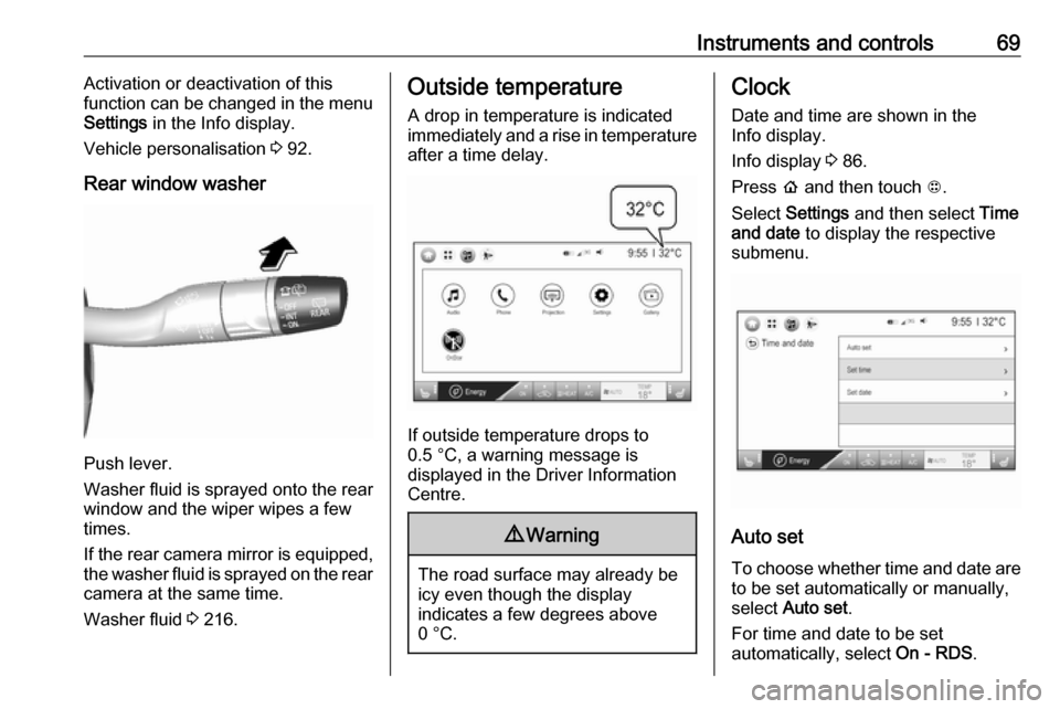
Rear window washer
Push lever.
Washer fluid is sprayed onto the rear
window and the wiper wipes a few
times.
If the rear camera mirror is equipped,
the washer fluid is sprayed on the rear camera at the same time.
Washer fluid 3 216.
Outside temperature
A drop in temperature is indicated
immediately and a rise in temperature
after a time delay.
If outside temperature drops to
0.5 °C, a warning message is
displayed in the Driver Information
Centre.
9 Warning
The road surface may already be
icy even though the display
indicates a few degrees above
0 °C.
Clock
Date and time are shown in the
Info display.
Info display 3 86.
Press p and then touch 1.
Select Settings and then select Time
and date to display the respective
submenu.
Auto set
To choose whether time and date are to be set automatically or manually,
select Auto set .
For time and date to be set
automatically, select On - RDS.
Page 72 of 265
70Instruments and controlsFor time and date to be set manually,select Off - Manual . If Auto set is set
to Off - Manual , the submenu items
Set time and Set date become
available.
Set time To adjust the time settings, select Set
time .
Touch + and - to adjust the settings.
To select a time mode, select 12 hr or
24 hr format.
If 12 hour format is selected, touch R or S to adjust AM or PM .
Set date To adjust the date settings, select Set
date .
Touch + and - to adjust the settings.Power outlets
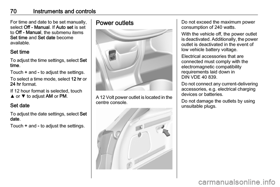
A 12 Volt power outlet is located in the
centre console.
Do not exceed the maximum power
consumption of 240 watts.
With the vehicle off, the power outlet
is deactivated. Additionally, the power
outlet is deactivated in the event of
low vehicle battery voltage.
Electrical accessories that are
connected must comply with the
electromagnetic compatibility
requirements laid down in
DIN VDE 40 839.
Do not connect any current-delivering
accessories, e.g. electrical charging
devices or batteries.
Do not damage the outlets by using
unsuitable plugs.
Page 73 of 265
Instruments and controls71USB charging port
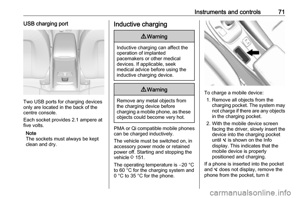
Two USB ports for charging devices
only are located in the back of the
centre console.
Each socket provides 2.1 ampere at
five volts.
Note
The sockets must always be kept
clean and dry.
Inductive charging9 Warning
Inductive charging can affect the
operation of implanted
pacemakers or other medical
devices. If applicable, seek
medical advice before using the
inductive charging device.
9 Warning
Remove any metal objects from
the charging device before
charging a mobile phone, as these
objects could become very hot.
PMA or Qi compatible mobile phones can be charged inductively.
The vehicle must be switched on, in
accessory power mode or retained
power off. Starting and stopping the
vehicle 3 151.
The operating temperature is −20 °C
to 60 °C for the charging system and
0 °C to 35 °C for the phone.
To charge a mobile device:
1. Remove all objects from the charging pocket. The system may
not charge if there are any objects
in the charging pocket.
2. With the mobile device screen facing the driver, slowly insert the
device into the charging pocket
until 0 is shown on the Info
display. This indicates that the
mobile device is properly
positioned and charging.
If a phone is inserted into the pocket
and 0 does not display, remove the
phone from the pocket, turn it
Page 74 of 265

72Instruments and controls180 degrees, and wait three seconds
before inserting the phone into the
pocket again.
Page 75 of 265
Instruments and controls73Warning lights, gauges and indicatorsInstrument cluster
Page 76 of 265

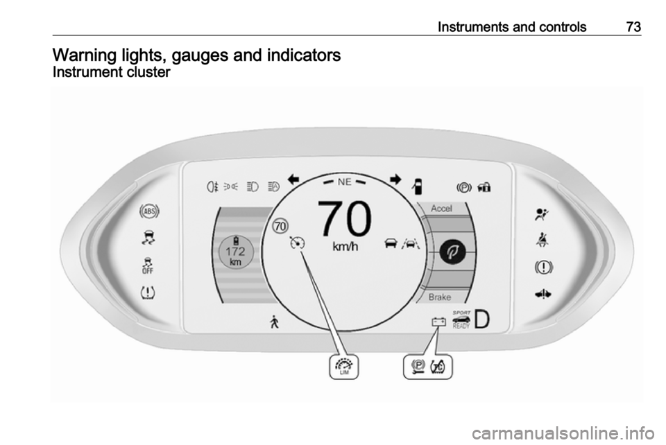
74Instruments and controlsOverviewOTurn signal 3 78XSeat belt reminder 3 78vAirbag and belt tensioners
3 79VAirbag deactivation 3 79pCharging system 3 796Service vehicle soonRBrake system 3 80mElectric parking brake
3 80jElectric parking brake fault
3 80uAntilock brake system
(ABS) 3 803Sport mode 3 154aLane keep assist 3 81aElectronic Stability Control
off 3 81bElectronic Stability Control
and Traction Control
system 3 81kTraction Control system off
3 81wTyre pressure monitoring
system 3 81dImmobiliser 3 814Vehicle ready 3 828Exterior light 3 82CHigh beam 3 82fHigh beam assist 3 82øRear fog light 3 82mCruise control 3 82AVehicle detected ahead
3 827Pedestrian detected aheadLSpeed limiter 3 82LTraffic sign assistant
3 82hDoor open 3 83
Reconfigurable instrument cluster
The cluster layout can be changed.
Use the steering wheel control to
move between the different display
zones and scroll through the different displays.
There are three display
configurations to choose from:
● Basic configuration displays the
speedometer with a simplified
high voltage battery gauge and
efficiency light.
● Standard configuration displays
the speedometer with a high
voltage battery gauge and
efficiency gauge.
● Enhanced configuration displays
the speedometer with high
voltage battery gauge, efficiency
ring, and power gauge.
Driver Information Centre 3 83.
Page 77 of 265
Instruments and controls75Speedometer
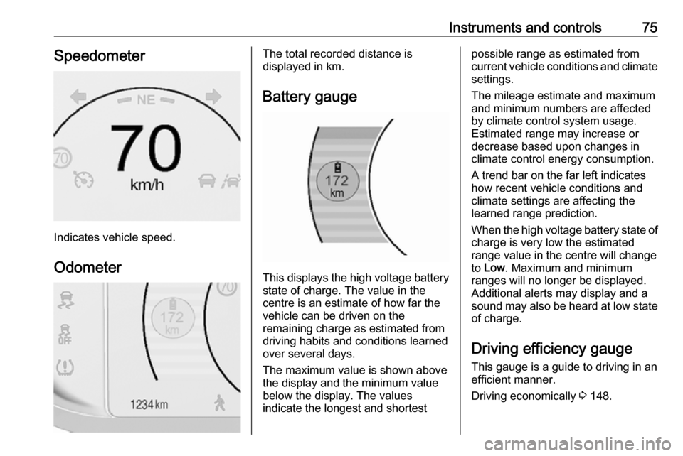
Indicates vehicle speed.
Odometer
The total recorded distance is
displayed in km.
Battery gauge
This displays the high voltage battery state of charge. The value in the
centre is an estimate of how far the
vehicle can be driven on the
remaining charge as estimated from
driving habits and conditions learned
over several days.
The maximum value is shown above
the display and the minimum value
below the display. The values
indicate the longest and shortest
possible range as estimated from
current vehicle conditions and climate
settings.
The mileage estimate and maximum
and minimum numbers are affected
by climate control system usage.
Estimated range may increase or
decrease based upon changes in
climate control energy consumption.
A trend bar on the far left indicates
how recent vehicle conditions and
climate settings are affecting the
learned range prediction.
When the high voltage battery state of charge is very low the estimated
range value in the centre will change
to Low . Maximum and minimum
ranges will no longer be displayed.
Additional alerts may display and a
sound may also be heard at low state
of charge.
Driving efficiency gaugeThis gauge is a guide to driving in an
efficient manner.
Driving economically 3 148.
Page 78 of 265

76Instruments and controlsEfficient drivingEfficient driving is indicated by:
● Basic layout: keeping the gauge and the leaf green.
● Standard layout: keeping the ball
green and in the centre of the
gauge.
● Enhanced layout: keeping the outer ring of the speedometer
green.
Inefficient acceleration
Inefficient acceleration is indicated
by:
● Basic layout: the gauge and the leaf turn yellow.
● Standard layout: the ball turns yellow and moves to the top end.
● Enhanced layout: the outer ring of the speedometer turns yellow
and the gauge moves to the top
end.
Aggressive braking
Aggressive braking is indicated by: ● Basic layout: the gauge and the leaf turn yellow.
● Standard layout: the ball turns yellow and moves to the bottom
end.
● Enhanced layout: the outer ring of the speedometer turns yellow
and the gauge moves to the
bottom end.
Driving economically 3 148, Driver
Information Centre 3 83.
Page 79 of 265
Instruments and controls77Power indicator gauge
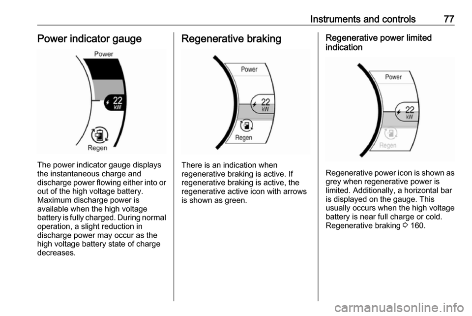
The power indicator gauge displays
the instantaneous charge and
discharge power flowing either into or out of the high voltage battery.
Maximum discharge power is
available when the high voltage
battery is fully charged. During normal
operation, a slight reduction in
discharge power may occur as the
high voltage battery state of charge
decreases.
Regenerative braking
There is an indication when
regenerative braking is active. If
regenerative braking is active, the regenerative active icon with arrowsis shown as green.
Regenerative power limited
indication
Regenerative power icon is shown as grey when regenerative power is
limited. Additionally, a horizontal bar
is displayed on the gauge. This
usually occurs when the high voltage
battery is near full charge or cold.
Regenerative braking 3 160.
Page 80 of 265
78Instruments and controlsTotal vehicle range
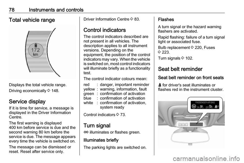
Displays the total vehicle range.
Driving economically 3 148.
Service display If it is time for service, a message is
displayed in the Driver Information
Centre.
The first warning is displayed
400 km before service is due and the
second warning 80 km before the
service is due. The message appears every time the vehicle is switched on.
The message can be dismissed or
reset. Reset after service only.
Driver Information Centre 3 83.
Control indicators
The control indicators described are
not present in all vehicles. The
description applies to all instrument
versions. Depending on the
equipment, the position of the control indicators may vary. When the vehicle
is switched on, most control indicators
will illuminate briefly as a functionality test.
The control indicator colours mean:red:danger, important reminderyellow:warning, information, faultgreen:confirmation of activationblue:confirmation of activationwhite:confirmation of activation,
system ready
Control indicators 3 73.
Turn signal
O illuminates or flashes green.
Illuminates briefly The parking lights are switched on.
Flashes
A turn signal or the hazard warning
flashers are activated.
Rapid flashing: failure of a turn signal
light or associated fuse.
Bulb replacement 3 220, Fuses
3 223.
Turn signals 3 102.
Seat belt reminder Seat belt reminder on front seats
X for driver's seat illuminates or
flashes red in the instrument cluster.