height OPEL AMPERA E 2017.5 Owner's Manual
[x] Cancel search | Manufacturer: OPEL, Model Year: 2017.5, Model line: AMPERA E, Model: OPEL AMPERA E 2017.5Pages: 265, PDF Size: 6.24 MB
Page 7 of 265
In brief5Seat adjustmentLongitudinal adjustment
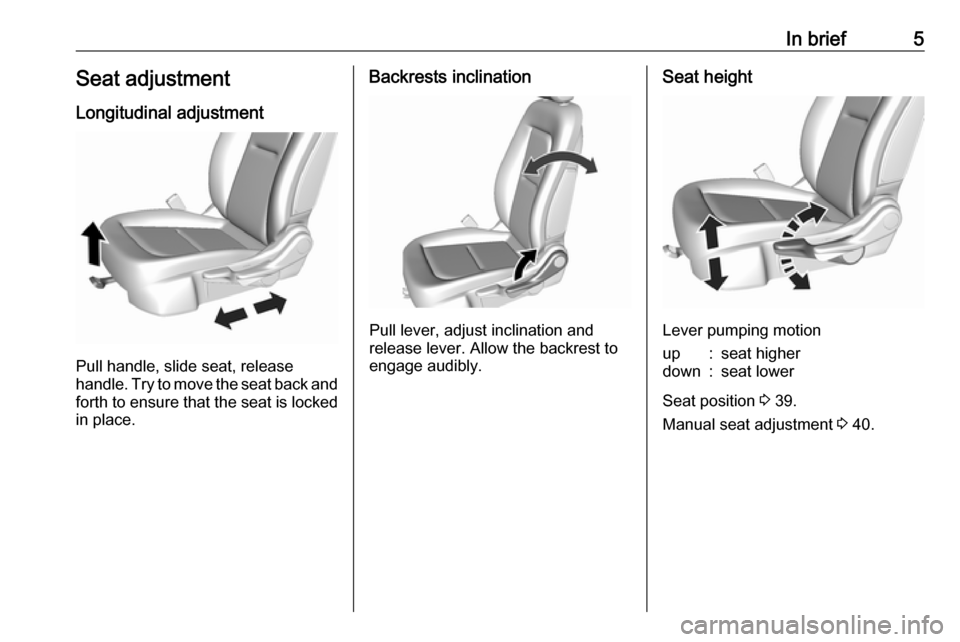
Pull handle, slide seat, release
handle. Try to move the seat back and forth to ensure that the seat is locked
in place.
Backrests inclination
Pull lever, adjust inclination and
release lever. Allow the backrest to
engage audibly.
Seat height
Lever pumping motion
up:seat higherdown:seat lower
Seat position 3 39.
Manual seat adjustment 3 40.
Page 8 of 265
6In briefHead restraint adjustment
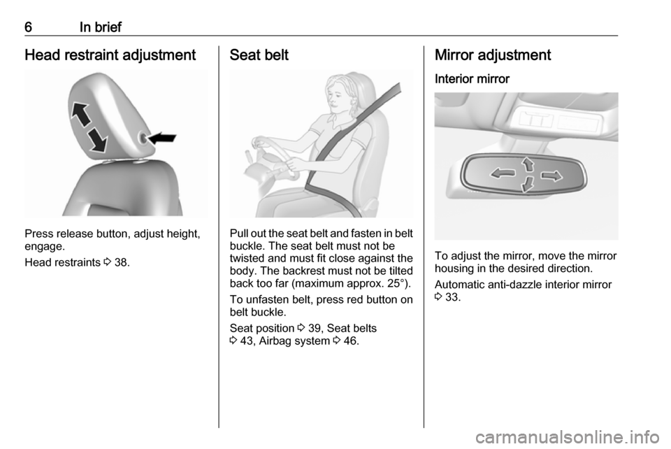
Press release button, adjust height,
engage.
Head restraints 3 38.
Seat belt
Pull out the seat belt and fasten in belt
buckle. The seat belt must not be
twisted and must fit close against the
body. The backrest must not be tilted back too far (maximum approx. 25°).
To unfasten belt, press red button on belt buckle.
Seat position 3 39, Seat belts
3 43, Airbag system 3 46.
Mirror adjustment
Interior mirror
To adjust the mirror, move the mirror
housing in the desired direction.
Automatic anti-dazzle interior mirror
3 33.
Page 40 of 265
38Seats, restraintsSeats, restraintsHead restraints............................ 38
Front seats ................................... 39
Seat position .............................. 39
Manual seat adjustment ............40
Armrest ...................................... 41
Heating ...................................... 42
Rear seats ................................... 43
Armrest ...................................... 43
Heating ...................................... 43
Seat belts ..................................... 43
Three-point seat belt .................44
Airbag system .............................. 46
Front airbag system ...................49
Side airbag system ....................49
Curtain airbag system ...............50
Airbag deactivation ....................50
Child restraints ............................. 52
Child restraint systems ..............52
Child restraint installation locations ................................... 54Head restraints
Position9 Warning
Only drive with the head restraint
set to the proper position.
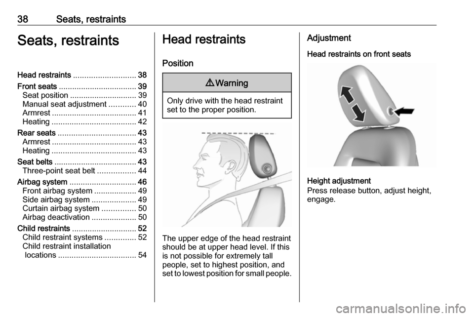
The upper edge of the head restraint
should be at upper head level. If this
is not possible for extremely tall
people, set to highest position, and
set to lowest position for small people.
Adjustment
Head restraints on front seats
Height adjustment
Press release button, adjust height,
engage.
Page 41 of 265
Seats, restraints39Head restraints on rear seats
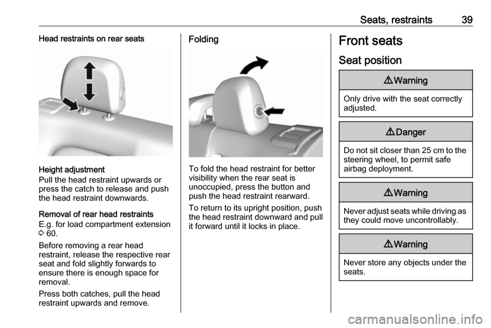
Height adjustment
Pull the head restraint upwards or
press the catch to release and push the head restraint downwards.
Removal of rear head restraints
E.g. for load compartment extension
3 60.
Before removing a rear head
restraint, release the respective rear
seat and fold slightly forwards to
ensure there is enough space for
removal.
Press both catches, pull the head restraint upwards and remove.
Folding
To fold the head restraint for better
visibility when the rear seat is
unoccupied, press the button and
push the head restraint rearward.
To return to its upright position, pushthe head restraint downward and pull
it forward until it locks in place.
Front seats
Seat position9 Warning
Only drive with the seat correctly
adjusted.
9 Danger
Do not sit closer than 25 cm to the
steering wheel, to permit safe
airbag deployment.
9 Warning
Never adjust seats while driving as
they could move uncontrollably.
9 Warning
Never store any objects under the
seats.
Page 42 of 265
40Seats, restraints
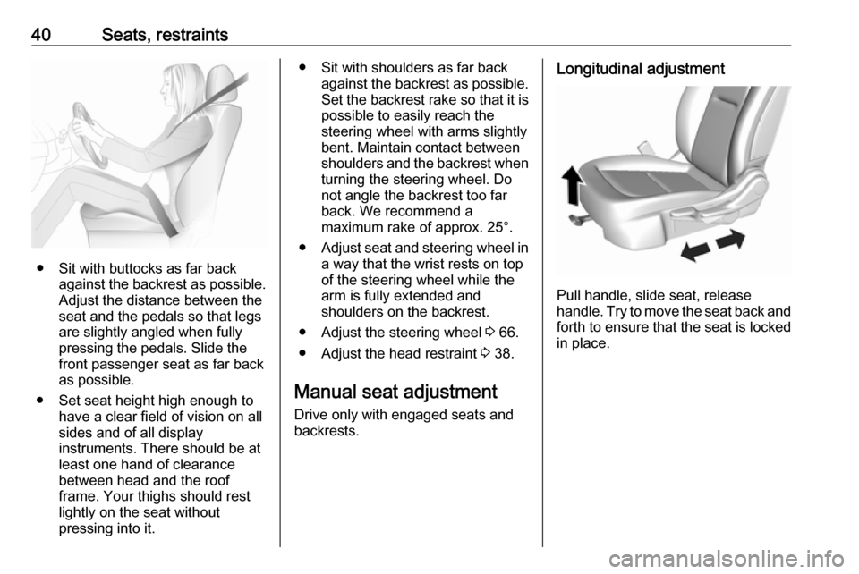
● Sit with buttocks as far backagainst the backrest as possible.
Adjust the distance between the
seat and the pedals so that legs
are slightly angled when fully
pressing the pedals. Slide the
front passenger seat as far back
as possible.
● Set seat height high enough to have a clear field of vision on all
sides and of all display
instruments. There should be at
least one hand of clearance
between head and the roof
frame. Your thighs should rest
lightly on the seat without
pressing into it.
● Sit with shoulders as far back against the backrest as possible.
Set the backrest rake so that it is possible to easily reach the
steering wheel with arms slightly
bent. Maintain contact between
shoulders and the backrest when
turning the steering wheel. Do
not angle the backrest too far
back. We recommend a
maximum rake of approx. 25°.
● Adjust seat and steering wheel in
a way that the wrist rests on top
of the steering wheel while the
arm is fully extended and
shoulders on the backrest.
● Adjust the steering wheel 3 66.
● Adjust the head restraint 3 38.
Manual seat adjustment Drive only with engaged seats and
backrests.Longitudinal adjustment
Pull handle, slide seat, release
handle. Try to move the seat back and forth to ensure that the seat is locked
in place.
Page 43 of 265

Seats, restraints41Backrest inclination
Pull lever, adjust inclination and
release lever. Allow the backrest to
engage audibly.
Seat height
Lever pumping motion
up:seat higherdown:seat lowerArmrest
The armrest can be slid forwards by
9 cm. Under the armrest there is a
storage compartment.
Armrest storage 3 59.
Page 184 of 265
182Driving and operatingmirror, when detecting objects that
may not be visible in the interior and
exterior mirrors.
The radar distance sensors are
located in the rear bumper.9 Warning
Side blind spot alert does not
replace driver vision.
The system does not detect:
● vehicles outside the side blind zones which may be rapidly
approaching
● pedestrians, cyclists or animals
Before changing a lane, always
check all mirrors, look over the
shoulder and use the turn signal.
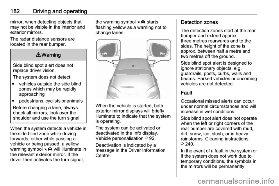
When the system detects a vehicle in the side blind zone while driving
forwards, either while passing a
vehicle or being passed, a yellow
warning symbol F will illuminate in
the relevant exterior mirror. If the
driver then activates the turn signal,
the warning symbol F starts
flashing yellow as a warning not to
change lanes.
When the vehicle is started, both
exterior mirror displays will briefly illuminate to indicate that the system
is operating.
The system can be activated or
deactivated in the Info display.
Vehicle personalisation 3 92.
Deactivation is indicated by a
message in the Driver Information
Centre.
Detection zones
The detection zones start at the rear
bumper and extend approx.
three metres rearwards and to the
sides. The height of the zone is
approx. between half a metre and
two metres off the ground.
Side blind spot alert is designed to ignore stationary objects, e.g.
guardrails, posts, curbs, walls and
beams. Parked vehicles or oncoming
vehicles are not detected.
Fault
Occasional missed alerts can occur
under normal circumstances and will
increase in wet conditions.
Side blind spot alert does not operate when the left or right corners of the
rear bumper are covered with mud,
dirt, snow, ice, slush, or in heavy
rainstorms. Cleaning instructions
3 240.
In the event of a fault in the system or if the system does not work due to
temporary conditions, the symbols in
the mirrors will be permanently
Page 185 of 265

Driving and operating183illuminated and a message is
displayed in the Driver Information
Centre. Seek the assistance of a
workshop.
Lane change alert Additional to the side blind spot alert
3 181, lane change alert recognises
rapidly approaching vehicles from
behind on parallel lanes next to your
vehicle.
If the vehicle is equipped with lane
change alert, side blind spot alert is
always included.
The system alerts visually in each
exterior mirror when detecting rapidly
approaching vehicles from behind.
The radar distance sensors are
located in the rear bumper.9 Warning
Lane change alert does not
replace driver vision.
Before changing a lane, always
check all mirrors, look over the
shoulder and use the turn signal.
When the system detects an
approaching vehicle from behind
which drives considerably faster, the
yellow warning symbol F will
illuminate in the relevant exterior mirror. If the driver then activates the
turn signal, the warning symbol F
starts flashing yellow as a warning not to change lanes.
Lane change alert is active at all
speeds.
When the vehicle is started, both
exterior mirror displays will briefly come on to indicate that the system is operating.
Detection zones
The system sensors cover a zone of
approx. 3.5 metres parallel on both
vehicle sides and approx.
three metres rearwards on side blind
zone alert (A) and approx. 70 metres
rearwards on lane change alert (B) on
parallel lanes. The zones start at each exterior mirror. The height of the zone
is approx. between 0.5 metres and
two metres off the ground.
Deactivation Activation or deactivation of the lanechange alert can be set in the vehicle personalisation menu in the Info
display.
Page 210 of 265

208Driving and operatingNote
By choosing a reduced charge level,
the charging time is increased.
Charge limit selection can be made
using the Charge limit preference
screen on the Info display. Charge limit selection 3 197.
Grounding instructions This product must be grounded. If thisproduct should malfunction or break
down, grounding provides a path of
least resistance for electric current to
reduce the risk of electric shock. This
product is equipped with a cord that
has an equipment grounding
conductor and a grounding plug. The plug must be plugged into an
appropriate outlet that is properly
installed and grounded in accordance with all local codes and ordinances.9 Warning
Improper connection of the charge
cord ground may cause electrical
shock. Check with a qualified
electrician if there is doubt as to
whether the charge circuit is
properly grounded. Do not modify
the plug provided with the product.
If it will not fit the electrical outlet,
have a proper electrical outlet
installed by a qualified electrician.
Charge cord mounting
instructions
Choose an appropriate, solid location for mounting the charge cord. The
appropriate height for mounting the
charge cord is 91 cm from the floor.
Space the holes 18.7 cm apart.
Install the mounting screws leaving
the head of the screws 5 mm from the
surface.
Securely mount the charge cord on to
the screws.
Connect the wall plug to the electrical
outlet.
Connect the vehicle plug to the
charge port.
Electrical requirementsCaution
Do not use portable or stationary
backup generating equipment to charge the vehicle. This may
cause damage to the vehicle's
charging system. Only charge the
vehicle from utility supplied power.
Charge limit selection 3 197.
Reduced limit mode allows a non-
dedicated circuit to be used but
increases the charging time.
This vehicle is capable of being
charged with standard vehicle
charging equipment complying with
one or more of the following
standards:
● SAE J1772
● SAE J2847–2
● IEC 61851-1
● IEC 61851-22
● IEC 61851-23
● IEC 61851-24
● IEC 62196-1
Page 216 of 265
214Vehicle care
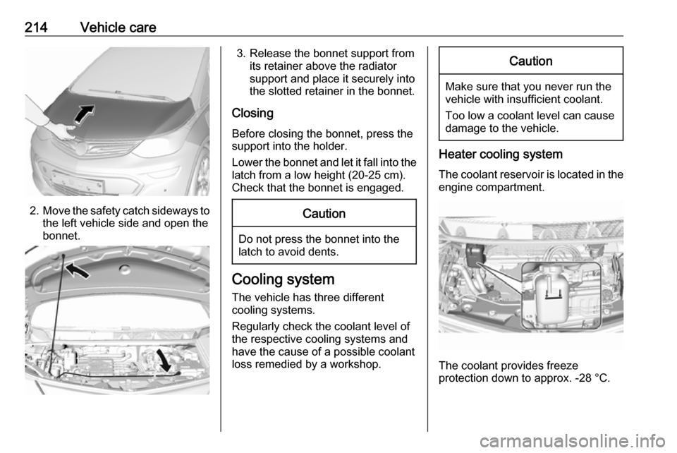
2.Move the safety catch sideways to
the left vehicle side and open the
bonnet.
3. Release the bonnet support from its retainer above the radiator
support and place it securely into
the slotted retainer in the bonnet.
Closing Before closing the bonnet, press the
support into the holder.
Lower the bonnet and let it fall into the latch from a low height (20-25 cm).
Check that the bonnet is engaged.Caution
Do not press the bonnet into the
latch to avoid dents.
Cooling system
The vehicle has three different
cooling systems.
Regularly check the coolant level of
the respective cooling systems and
have the cause of a possible coolant
loss remedied by a workshop.
Caution
Make sure that you never run the
vehicle with insufficient coolant.
Too low a coolant level can cause damage to the vehicle.
Heater cooling system
The coolant reservoir is located in the engine compartment.
The coolant provides freeze
protection down to approx. -28 °C.