display OPEL AMPERA E 2018.5 Manual user
[x] Cancel search | Manufacturer: OPEL, Model Year: 2018.5, Model line: AMPERA E, Model: OPEL AMPERA E 2018.5Pages: 273, PDF Size: 6.6 MB
Page 199 of 273

Driving and operating1975. Once charging, the DC vehicleplug will be locked to the DC
charge port and cannot be
disconnected while charging is
active.
6. Verify that the charging status indicator illuminates on top of the
instrument panel and a horn chirp occurs.
Charging status 3 204.Caution
Do not attempt to disconnect the
DC vehicle plug while charging is
active. This action may damage vehicle or charging station
hardware.
Stop charging
Controls on the charging station can
be used to stop the charge process at any time. Or press and hold 5 on the
electronic key. This will also unlock
the vehicle plug.
To stop charging when inside the
vehicle, you may use the Stop button
on the Charging screen.
Programmable charging 3 197.
There is also an available mobile app
with several charging functions.
Smartphone remote function 3 26.Automatic power supply cut-off
When the vehicle no longer needs to
use power from the charging station,
the charging process will be stopped.
Use the electronic key to unlock the
DC vehicle plug.
Energy can still be consumed from
the charging station when the
vehicle’s displays and indicators
show that the high voltage battery is
fully charged. This is to ensure the
high voltage battery is in optimal
temperature operating range to
maximise vehicle range.
Programmable charging 3 197.
End charging
1. Wait until the charging process has been fully stopped, the
vehicle plug is unlocked and the
charging status indicator is solid
green or off.
2. Unplug the DC vehicle plug from the DC charge port on the vehicle
and close the dust cover.
3. Close the charge port door by pressing firmly in the centre to
latch properly.
4. Manually disengage the electric parking brake before driving the
vehicle.
5. To start another DC charge, remove the DC vehicle plug and
reconnect.
Programmable charging
Programmable charge modes To view the current charge mode
status on the Info Display, touch Energy and then Charging.
The charge start and charge
complete time estimations are also
displayed on the screen. These
estimations are most accurate when
the vehicle is plugged in and in
moderate temperature conditions.
Also, to get an accurate time
estimate, the vehicle uses an internal
clock for programmable charging, not the clock in the instrument panel.
Page 200 of 273
198Driving and operatingCharge mode selection
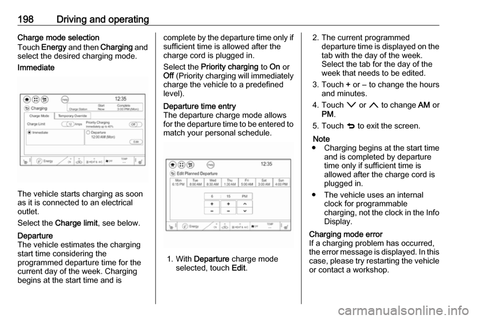
Touch Energy and then Charging and
select the desired charging mode.Immediate
The vehicle starts charging as soon
as it is connected to an electrical outlet.
Select the Charge limit , see below.
Departure
The vehicle estimates the charging start time considering the
programmed departure time for the
current day of the week. Charging
begins at the start time and iscomplete by the departure time only if
sufficient time is allowed after the
charge cord is plugged in.
Select the Priority charging to On or
Off (Priority charging will immediately
charge the vehicle to a predefined
level).Departure time entry
The departure charge mode allows
for the departure time to be entered to match your personal schedule.
1. With Departure charge mode
selected, touch Edit.
2. The current programmed
departure time is displayed on the
tab with the day of the week.
Select the tab for the day of the
week that needs to be edited.
3. Touch + or − to change the hours
and minutes.
4. Touch o or n to change AM or
PM .
5. Touch q to exit the screen.
Note
● Charging begins at the start time and is completed by departure
time only if sufficient time is
allowed after the charge cord is
plugged in.
● The vehicle uses an internal clock for programmable
charging, not the clock in the Info Display.Charging mode error
If a charging problem has occurred,
the error message is displayed. In this
case, please try restarting the vehicle or contact a workshop.
Page 203 of 273

Driving and operating201
Touch Edit electric rate schedule from
the Electric rate Schedule screen and
select the desired schedule.
● Yearly
● Summer / Winter
Summer / Winter schedule start date
entering
With Summer / Winter as the
preferred rate schedule, touch Edit on
the Summer tab next to the dates.
1. Touch + or − to change the month
and day for the start of Summer.
2. Select the Winter tab.3.Touch + or − to change the month
and day for the start of Winter.
4. Touch q to exit the screen.Electric rate schedule editing
Electric rate information from the
utility company for the charging
location is required.
1. Touch Edit electric rate schedule
from the Electric rate Schedule
screen and select the desired
schedule.
2. Touch Edit in the lower right
corner of the screen to edit the
electric rate schedule.
Both weekday and weekend
schedules must be set. The rate
schedule only applies for a
24-hour period, starting at 12 AM
and ending at 12 AM. There can
be five rate changes for each day; not all must be used.
3. Touch Set next to the row to be
edited.
4. Select Peak, Mid-peak , or Off-
peak . Use + or - to enter the time,
and o or n to change AM or
PM.
The finish times must be
consecutive. If a finish time does not follow a start time, an error
message displays.
5. Touch OK.
Page 205 of 273

Driving and operating203preference every time the vehicle is
returned to the saved Home location.
When the vehicle is not at the saved Home location, then the vehicle will
default to the lower limit of Charge
limit preference and the Charge
mode will be set to Immediate.
When Location-based charging is
On and the vehicle is away from the
saved Home location, then the
selection for the charge mode will be
disabled and the selection will be
greyed out.
After 90 days, a notification will
display and the Charge limit
preference will need to be reset for
the next 90 days. Important
information about portable electric
vehicle charging 3 205.
When the GPS location is not
available, dashes will be displayed
and location based charging will be disabled until the GPS is restored.
To use location based charging, a
Home location must first be stored.To store a Home location:
1. From the Energy home screen,
touch Energy settings .
2. Touch Location-based charging .
3. Touch Set home location v .
4. Touch OK.
5. Touch On to enable Location-
based charging .
To change the stored Home location:
1. Touch Update Home Location v
on the Location-based charging
screen.
2. Touch Update, then OK to set the
new home location.
● Touch Cancel to make no
changes.
● Touch Remove to clear the
location and turn location
based charging off.Charging interrupted or
overridden pop-up
The Charging override / interruption
occurred pop-up will appear if any of
the following conditions occur:
● The charging settings have been
modified via OnStar through the
website or the mobile app. For
example, the departure time
tables, the rate tables, or the
charge mode were updated using
the customer website (available
in select regions).
● There was an unintended loss of AC power during the plug-in
charge event. For example, there was a power outage or the
charge cord was unplugged from the wall.
Page 206 of 273

204Driving and operatingProgrammable charging disabled
When the programmable charging
system is disabled, the Unable to
charge screen will be displayed.
Programmed charging override
To temporarily override a delayed charge event, unplug the charge cord from the charge port and then plug it
back in within 5 seconds. A single
horn chirp will sound and charging will begin immediately.
To cancel a temporary override,
unplug the charge cord, wait for
10 seconds, and then plug the charge cord back in. A double horn chirp will
sound and charging will be delayed.
Programmable charging 3 197.
Charging status
The vehicle has a charging status
indicator at the centre of the
instrument panel near the
windscreen. When the vehicle is
plugged in and the vehicle power is
off, the charging status indicator
indicates the following:
● Short flashing green – One horn chirp: Vehicle is plugged in. High
voltage battery is not fully
charged. High voltage battery is
charging. Flash rate increases
from one to four flashes as the
high voltage battery charges.
● Short flashing green – Two audible beeps: Vehicle is
charging but will delay by
programmable charging at least
once before the charge is
complete. Flash rate increases
from one to four flashes as the high voltage battery charges.
● Short flashing green – Four audible beeps: Insufficient time to
fully charge by departure time due to the selected rate
preference. To increase the high
voltage battery state of charge at
the departure time perform a
delayed charging override.
Programmable charging 3 197.
● Long flashing green – Two horn chirps: Charging is delayed by
programmable charging.
Charging will begin later.
Page 210 of 273
208Driving and operatingfrom the electrical outlet and re-
plugging it. If the fault remains,
consult a workshop for a service.
● c solid green and d flashes red:
charge cord fault: The charge cord has detected a potential
problem with the charge cord.
Reset the charge cord by
unplugging from the electrical
outlet and re-plugging it. If the fault remains, seek the
assistance of a workshop.
If no status indicator is lit, ensure the
electrical outlet is powered.
Charge level selection9 Warning
If the capacity of the electrical
circuit or AC socket is not known,
only use the lowest charge level
until the circuit capacity has been
inspected by a qualified
electrician. Using a charge level
that exceeds either the electrical
circuit or the AC outlet capacity
may start a fire or damage the
electrical circuit.
Note
By choosing a reduced charge level,
the charging time is increased.
Charge limit selection can be made
using the Charge limit preference
screen on the Info Display.
Charge limit selection 3 197.
Grounding instructions This product must be grounded. If this
product should malfunction or break
down, grounding provides a path of
least resistance for electric current to
reduce the risk of electric shock. This product is equipped with a cord that
has an equipment grounding
conductor and a grounding plug. The
plug must be plugged into an
appropriate outlet that is properly
installed and grounded in accordance
with all local codes and ordinances.9 Warning
Improper connection of the charge
cord ground may cause electrical
shock. Check with a qualified
electrician if there is doubt as to
whether the charge circuit is
properly grounded. Do not modify
the plug provided with the product.
If it will not fit the electrical outlet,
have a proper electrical outlet
installed by a qualified electrician.
Charge cord mounting
instructions
Choose an appropriate, solid location for mounting the charge cord. The
appropriate height for mounting the
charge cord is 91 cm from the floor.
Space the holes 18.7 cm apart.
Install the mounting screws leaving
the head of the screws 5 mm from the
surface.
Securely mount the charge cord on to
the screws.
Connect the wall plug to the electrical
outlet.
Connect the vehicle plug to the
charge port.
Page 219 of 273
Vehicle care217When the vehicle has not been
running for at least 1 minute, the
maximum fluid level is at the top of the
reservoir body. When the vehicle is
running, the brake fluid level must be
between the MIN and MAX marks.
If the brake fluid level is below MIN
seek the assistance of a workshop.
After work is done on the brake
hydraulic system, make sure the fluid level is in the proper operating rangebetween the MIN and MAX marks
when the vehicle is running. Only use
high-performance brake fluid
approved for the vehicle. Consult a
workshop.
Brake fluid 3 248.
Vehicle battery9 Danger
Only a trained service technician
with the proper knowledge and
tools may inspect, test or replace
the high voltage battery.
Seek the assistance of a
workshop if the high voltage
battery needs service.
This vehicle has a high voltage
battery and a 12 V vehicle battery.
If the vehicle is involved in a crash, the
sensing system may shut down the
high voltage system. If this occurs,
the high voltage battery will be
disconnected and the vehicle will not
start.
A service message will be displayed
in the Driver Information Centre.
Before the vehicle can be operated
again, it must be serviced at a
workshop.
Airbag system 3 45.
A vehicle cover, which can reduce
sun loading on the vehicle and
improve high voltage battery life, is
available from your Opel Ampera-e
Service Partner.
The Opel Ampera-e authorised
repairer has information on how to recycle the high voltage battery.
Keep the vehicle plugged in, even
when fully charged, to keep the high
voltage battery temperature ready for
the next drive. This is important when
outside temperatures are extremely
hot or cold.
Refer to the replacement number
shown on the original 12 V vehicle
battery label if a new 12 V vehicle
battery is required. The vehicle has
an Absorbed Glass Mat (AGM) 12 V
vehicle battery.
Installation of a standard 12 V vehicle battery will result in reduced 12 V
vehicle battery life. When using a 12 V battery charger on the AGM12 V vehicle battery, note that somechargers have an AGM battery
setting on the charger. If available,
use the AGM setting on the charger
to limit charge voltage to 14.8 V.
Follow the charger manufacturer's
instructions.
Page 231 of 273
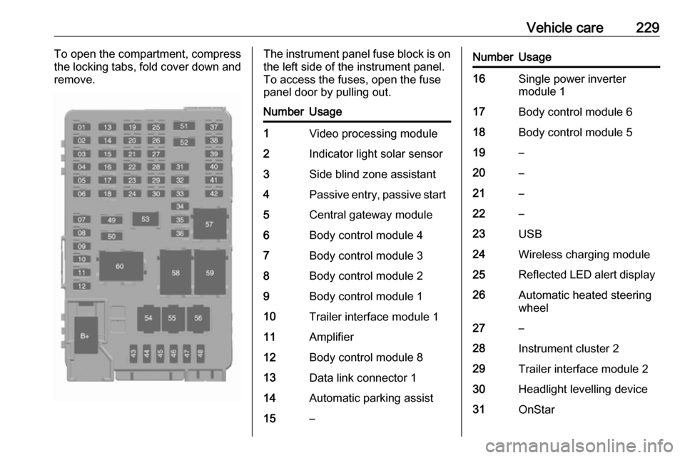
Vehicle care229To open the compartment, compress
the locking tabs, fold cover down and
remove.The instrument panel fuse block is on the left side of the instrument panel.
To access the fuses, open the fuse
panel door by pulling out.NumberUsage1Video processing module2Indicator light solar sensor3Side blind zone assistant4Passive entry, passive start5Central gateway module6Body control module 47Body control module 38Body control module 29Body control module 110Trailer interface module 111Amplifier12Body control module 813Data link connector 114Automatic parking assist15–NumberUsage16Single power inverter
module 117Body control module 618Body control module 519–20–21–22–23USB24Wireless charging module25Reflected LED alert display26Automatic heated steering
wheel27–28Instrument cluster 229Trailer interface module 230Headlight levelling device31OnStar
Page 235 of 273
Vehicle care233For the tyres approved for your
vehicle, refer to the EEC Certificate of
Conformity provided with your vehicle
or other national registration
documents.
The driver is responsible for correct
adjustment of tyre pressure.9 Warning
If the pressure is too low, this can
result in considerable tyre warm-
up and internal damage, leading to tread separation and even to tyre
blow-out at high speeds.
9 Warning
For specific tyres the
recommended tyre pressure as
shown in the tyre pressure table may exceed the maximum tyre
pressure as indicated on the tyre.
Never exceed the maximum tyre
pressure as indicated on the tyre.
If the tyre pressure must be reduced
or increased on a vehicle with tyre
pressure monitoring system, switch
off the vehicle.
Temperature dependency The tyre pressure depends on the
temperature of the tyre. During
driving, tyre temperature and
pressure increase. Tyre pressure
values provided on the tyre
information label and tyre pressure
chart are valid for cold tyres, which means at 20 °C.
The pressure increases by nearly
10 kPa for a 10 °C temperature
increase. This must be considered
when warm tyres are checked.
The tyre pressure value displayed in
the Driver Information Centre shows
the real tyre pressure. A cooled down
tyre will show a decreased value,
which does not indicate an air leak.Tyre pressure monitoring
system
The tyre pressure monitoring system
checks the pressure of all four tyres
once a minute when vehicle speed
exceeds a certain limit.Caution
Tyre pressure monitoring system
warns only about low tyre pressure condition and does not replace
regular tyre maintenance by the
driver.
All wheels must be equipped with pressure sensors and the tyres must
have the prescribed pressure.
Note
In countries where the tyre pressure
monitoring system is legally
required, the use of wheels without
pressure sensors will invalidate the
vehicle operating permit.
The current tyre pressures can be
shown in the Driver Information
Centre.
Page 236 of 273

234Vehicle care
To access the tyre pressure page,
choose vehicle info menu via right
steering wheel buttons and press
{ or } to select tyre pressure.
To reset the system: ● Press and hold 9 until the tyre
pressure monitoring system asks
for a check.
● Press 9 again to confirm. The
vehicle honks twice.
System status and pressure warnings
are displayed by a message
indicating the corresponding tyre in
the Driver Information Centre.
The system considers the tyre
temperature for the warnings.
Temperature dependency 3 232.
A detected low tyre pressure
condition is indicated by the control
indicator w 3 80.
If w illuminates, stop as soon as
possible and inflate the tyres as
recommended 3 254.
After inflating, some driving may be
required to update the tyre pressure
values in the Driver Information
Centre. During this time w may
illuminate.
If w illuminates at lower temperatures
and extinguishes after driving, this
could be an indicator for approaching a low tyre pressure condition. Check
tyre pressure.
Vehicle messages 3 89.
If the tyre pressure must be reduced or increased, switch off vehicle.
Winter tyres or additional wheel sets
must be fitted with sensors, otherwise the system will not work and control
indicator w illuminates continuously.
The tyre pressure monitoring system
malfunction indicator is combined
with the low tyre pressure control
indicator. If the system detects a
malfunction, w will flash for approx.
1 minute and then remain
continuously illuminated. This
sequence will continue upon
subsequent vehicle start-ups as long
as the malfunction exists.
If the malfunction indicator w is
illuminated, the system may not be
able to detect or signal low tyre
pressure as intended. Tyre pressure
monitoring system malfunctions may
occur for a variety of reasons,
including the installation of
replacement or alternate tyres or wheels on the vehicle that prevent the
tyre pressure monitoring system from functioning properly. Always check
the tyre pressure monitoring system
malfunction control indicator w after
replacing one or more tyres or wheels
on your vehicle to ensure that the