engine OPEL AMPERA E 2018.5 Manual user
[x] Cancel search | Manufacturer: OPEL, Model Year: 2018.5, Model line: AMPERA E, Model: OPEL AMPERA E 2018.5Pages: 273, PDF Size: 6.6 MB
Page 216 of 273
214Vehicle care3. Release the bonnet support fromits retainer above the radiator
support and place it securely into
the slotted retainer in the bonnet.
Closing
Before closing the bonnet, press the
support into the holder.
Lower the bonnet and let it fall into the latch from a low height (20-25 cm).
Check that the bonnet is engaged.Caution
Do not press the bonnet into the
latch to avoid dents.
Cooling system
The vehicle has three different
cooling systems.
Regularly check the coolant level of
the respective cooling systems and
have the cause of a possible coolant
loss remedied by a workshop.
Caution
Make sure that you never run the
vehicle with insufficient coolant.
A low coolant level can cause
damage to the vehicle.
Heater cooling system
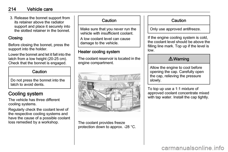
The coolant reservoir is located in the engine compartment.
The coolant provides freeze
protection down to approx. -28 °C.
Caution
Only use approved antifreeze.
If the engine cooling system is cold,
the coolant level should be above the
filling line mark. Top up if the level is
low.
9 Warning
Allow the engine to cool before
opening the cap. Carefully open
the cap, relieving the pressure
slowly.
To top up use a 1:1 mixture of
approved coolant concentrate mixed
with tap water. Install the cap tightly.
Page 217 of 273
Vehicle care215High voltage battery cooling
system9 Danger
The high voltage battery coolant
may only be serviced by a
qualified technician.
Improper handling could cause serious injuries or death.
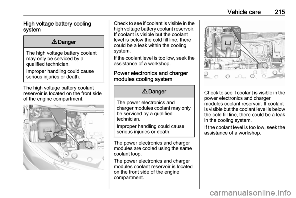
The high voltage battery coolantreservoir is located on the front side
of the engine compartment.
Check to see if coolant is visible in the high voltage battery coolant reservoir.
If coolant is visible but the coolant
level is below the cold fill line, there
could be a leak within the cooling
system.
If the coolant level is too low, seek the assistance of a workshop.
Power electronics and charger
modules cooling system9 Danger
The power electronics and
charger modules coolant may only be serviced by a qualified
technician.
Improper handling could cause serious injuries or death.
The power electronics and charger
modules are cooled using the same coolant loop.
The power electronics and charger
modules coolant reservoir is located
on the front side of the engine
compartment.
Check to see if coolant is visible in the
power electronics and charger
modules coolant reservoir. If coolant
is visible but the coolant level is below the cold fill line, there could be a leak
in the cooling system.
If the coolant level is too low, seek the assistance of a workshop.
Page 218 of 273
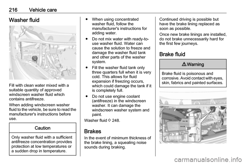
216Vehicle careWasher fluid
Fill with clean water mixed with a
suitable quantity of approved
windscreen washer fluid which
contains antifreeze.
When adding windscreen washer
fluid to the vehicle, be sure to read the
manufacturer's instructions before
use.
Caution
Only washer fluid with a sufficient
antifreeze concentration provides
protection at low temperatures or
a sudden drop in temperature.
● When using concentrated washer fluid, follow the
manufacturer's instructions for
adding water.
● Do not mix water with ready-to- use washer fluid. Water can
cause the solution to freeze and
damage the washer fluid tank
and other parts of the washer
system.
● Fill the washer fluid tank only three quarters full when it is verycold. This allows for fluid
expansion if freezing occurs,
which could damage the tank if it
is completely full.
● Do not use engine coolant (antifreeze) in the windscreen
washer. It can damage the
windscreen washer system and
paint.
Washer fluid 3 248.
Brakes In the event of minimum thickness ofthe brake lining, a squealing noise
sounds during braking.Continued driving is possible but
have the brake lining replaced as
soon as possible.
Once new brake linings are installed,
do not brake unnecessarily hard for
the first few journeys.
Brake fluid9 Warning
Brake fluid is poisonous and
corrosive. Avoid contact with eyes,
skin, fabrics and painted surfaces.
Page 220 of 273

218Vehicle careBatteries do not belong in household
waste. They must be disposed of at
an appropriate recycling collection
point.
There are connecting points for jump
starting in the engine compartment.
Jump starting 3 240.
Remove the 12 V vehicle battery
black negative (−) cable from the
12 V vehicle battery to prevent the
12 V vehicle battery from running
down, or use a battery trickle charger.
Ensure the vehicle is switched off
before connecting or disconnecting
the 12 V vehicle battery.
Vehicle storage 3 211.
Battery discharge protection 3 105.Warning label
Meaning of symbols:
● No sparks, naked flames or smoking.
● Always shield eyes. Explosive gases can cause blindness or
injury.
● Keep the 12 V vehicle battery out
of reach of children.
● The 12 V vehicle battery contains
sulphuric acid which could cause
blindness or serious burn
injuries.
● See the Owner's Manual for further information.
● Explosive gas may be present in the vicinity of the 12 V vehicle
battery.
Post-crash label
The post-crash label is located in the
door frame 3 152.
Page 222 of 273
220Vehicle careIf the vehicle is damaged in a crash,
the headlight aim may be affected. If
adjustment to the low beam is
necessary, seek the assistance of a
workshop.Bulb replacement
Switch off the vehicle and the relevant
light.
Only hold a new bulb at the base. Do not touch the bulb glass with bare
hands.
Use only the same bulb type for
replacement.
Replace headlight bulbs from within
the engine compartment.
Bulb check
After a bulb replacement, switch on
the vehicle, operate and check the
lights.
Halogen bulbs9 Warning
Halogen bulbs have pressurised
gas inside and can burst if you
drop or scratch the bulb. You or others could be injured. Be sure to read and follow the instructions onthe bulb package.
Xenon headlights9 Danger
Xenon headlights work under
extremely high electrical voltage.
Do not touch. Have bulbs replaced by a workshop.
Bulbs for front turn lights and
corner lighting can be changed.
Sidelight / Daytime running lights are
designed as Light Emitting Diodes
(LEDs) and cannot be replaced.
Front turn lights Each turn light is accessible from
behind via the respective wheel
house:
Page 225 of 273

Vehicle care223Electrical system
High voltage devices and wiring9 Warning
Exposure to high voltage may
cause shock, burns, and even
death. The high voltage
components in the vehicle should
only be serviced by specially
trained technicians.
High voltage components are
identified by labels. Do not
remove, open, take apart, or
modify these components. High
voltage cable or wiring has orange covering. Do not probe, tamper
with, cut, or modify high voltage
cable or wiring.
Electrical system overload
The vehicle has fuses and circuit
breakers to protect against an
electrical system overload.
If the current electrical load is too
heavy, the circuit breaker will open
and close, protecting the circuit until
the current load returns to normal or the problem is fixed. This greatly
reduces the chance of circuit
overload and fire caused by electrical
problems.
Fuses and circuit breakers protect the
following parts in the vehicle:
● Headlight wiring
● Windscreen wiper motor
● Power windows and other power accessories
Headlight wiring An electrical overload may cause the
lights to go on and off or in some
cases to remain off. In this case, have
the headlight wiring checked
immediately by a workshop.
Windscreen wipers
If the wiper motor overheats due to
blockage from heavy snow or ice, the windscreen wipers will stop until themotor has cooled down and the wiper
control has been turned off. Afterremoval of the blockage, the wiper
motor will restart when moving the
wiper control to the desired operating
position.
Although the circuit is protected from
electrical overload, mechanical
overload due to heavy snow or ice
may cause wiper linkage damage.
Always clear ice and heavy snow
from the windscreen before using the windscreen wipers. If the overload is
caused by an electrical problem and
not snow or ice, it must be serviced.
Fuses
Data on the replacement fuse must match the data on the defective fuse.
There are two fuse boxes in the
vehicle:
● at the front left side of the engine
compartment
● at the left side of the instrument panel
Before replacing a fuse, turn off the
respective switch and the vehicle.
Page 226 of 273
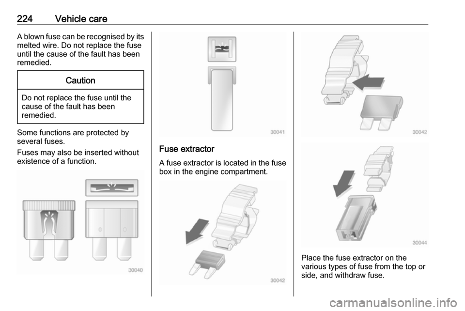
224Vehicle careA blown fuse can be recognised by itsmelted wire. Do not replace the fuse
until the cause of the fault has been
remedied.Caution
Do not replace the fuse until the
cause of the fault has been
remedied.
Some functions are protected by
several fuses.
Fuses may also be inserted without
existence of a function.
Fuse extractor
A fuse extractor is located in the fuse
box in the engine compartment.
Place the fuse extractor on the
various types of fuse from the top or
side, and withdraw fuse.
Page 227 of 273
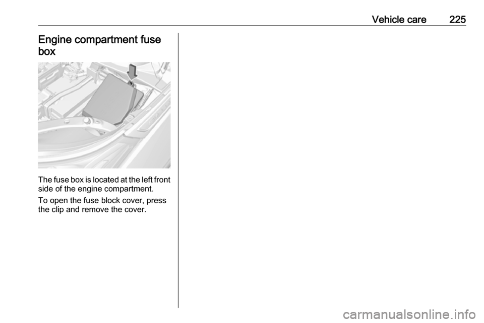
Vehicle care225Engine compartment fusebox
The fuse box is located at the left front
side of the engine compartment.
To open the fuse block cover, press
the clip and remove the cover.
Page 230 of 273
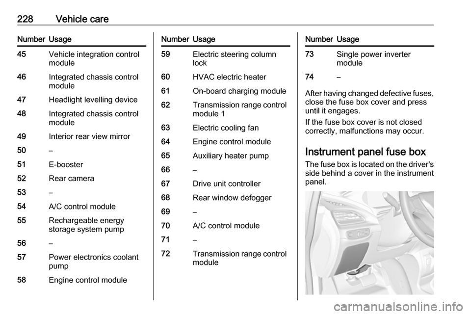
228Vehicle careNumberUsage45Vehicle integration control
module46Integrated chassis control
module47Headlight levelling device48Integrated chassis control
module49Interior rear view mirror50–51E-booster52Rear camera53–54A/C control module55Rechargeable energy
storage system pump56–57Power electronics coolant
pump58Engine control moduleNumberUsage59Electric steering column
lock60HVAC electric heater61On-board charging module62Transmission range control
module 163Electric cooling fan64Engine control module65Auxiliary heater pump66–67Drive unit controller68Rear window defogger69–70A/C control module71–72Transmission range control
moduleNumberUsage73Single power inverter
module74–
After having changed defective fuses,
close the fuse box cover and press
until it engages.
If the fuse box cover is not closed
correctly, malfunctions may occur.
Instrument panel fuse boxThe fuse box is located on the driver's
side behind a cover in the instrument
panel.
Page 240 of 273

238Vehicle care2. Remove the compressor and thesealant bottle.
3. Remove the electrical connection cable and air hose from the
storage compartments on the
underside of the compressor.
4. Screw the compressor air hose to
the connection on the sealant
bottle.
5. Fit the sealant bottle into the retainer on the compressor.
Set the compressor near the tyre
in such a way that the sealant
bottle is upright.6. Unscrew valve cap from defective
tyre.
7. Screw the filler hose to the tyre valve.
8. The switch on the compressor must be set to J.
9. Connect the compressor plug to the power outlet or cigarette
lighter socket.
To avoid discharging the battery, we recommend running the
engine.