reset OPEL AMPERA E 2018.5 Manual user
[x] Cancel search | Manufacturer: OPEL, Model Year: 2018.5, Model line: AMPERA E, Model: OPEL AMPERA E 2018.5Pages: 273, PDF Size: 6.6 MB
Page 168 of 273

166Driving and operatingCruise control is deactivated, but not
switched off. Last stored speed
remains in memory for later speed
resume.
Automatic deactivation: ● Vehicle speed is below approx. 25 km/h.
● The brake pedal is depressed.
● The selector lever is in N.
● The Traction Control system or Electronic Stability Control is
operating.
Switching off the system
Press m, control indicator m in
instrument cluster extinguishes. The
stored speed is deleted.
Speed limiter
The speed limiter prevents the
vehicle exceeding a preset maximum
speed.
The maximum speed can be set at
speeds above 25 km/h.The driver can only accelerate up to
the preset speed. Deviations from the
limited speed may occur when driving downhill.
The preset speed limit is displayed in
the Driver Information Centre when
the system is active.
Activation of the functionality
Press L.
If cruise control has been activated
beforehand, it is switched off when
speed limiter is activated and the
control indicator m extinguishes.
Set speed limit
Accelerate to the desired speed and
briefly press SET/-: the current speed
is stored as maximum speed.
Speed limit is displayed in the Driver
Information Centre.
Change speed limit
With speed limiter active, press
RES/+ to increase or SET/- to
decrease the desired maximum
speed.
Page 192 of 273

190Driving and operating
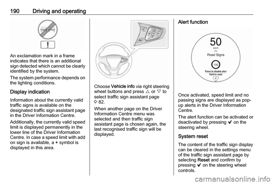
An exclamation mark in a frame
indicates that there is an additional
sign detected which cannot be clearly
identified by the system.
The system performance depends on the lighting conditions.
Display indication Information about the currently valid
traffic signs is available on the
designated traffic sign assistant page
in the Driver Information Centre.
Additionally, the currently valid speed limit is displayed permanently in the
lower line of the Driver Information
Centre. In case a speed limit with add
on sign is available, a + symbol is
displayed in this area.
Choose Vehicle info via right steering
wheel buttons and press { or } to
select traffic sign assistant page
3 82.
When another page on the Driver Information Centre menu was
selected and then traffic sign
assistant page is chosen again, the
last recognised traffic sign will be
displayed.
Alert function
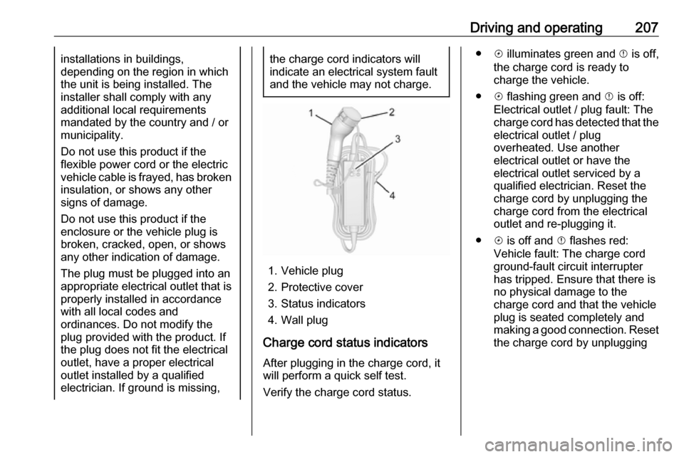
Once activated, speed limit and no
passing signs are displayed as pop-
up alerts in the Driver Information
Centre.
The alert function can be activated or
deactivated by pressing 9 on the
steering wheel.
System reset
The content of the traffic sign display
can be cleared in the settings menu
of the traffic sign assistant page by
selecting Reset and confirm by
pressing 9 on the steering wheel
controls.
Page 201 of 273

Driving and operating199
Charge limit selection
The charge limit setting allows the
vehicle’s charge limit to be selected
so it matches the capability of the
charging location. If the vehicle
consistently stops charging after
plugging in, or if a circuit breaker
continues to trip, reducing to a lower
charge limit setting may resolve the
issue.
The charge limit setting should be
configured to match the electrical
current rating for the electrical outlet
that the charge cord is connected to.
On the Charge mode screen, toggle
the Charge limit selection between:
● 10 A
● 6 A
The charge limit setting must be
updated prior to the vehicle being
charged and the charge limit setting
will reset to a default value when the
vehicle is shifted from P.9 Warning
If the capacity of the electrical
circuit or AC socket is not known,
only use the lowest charge level
until the circuit capacity has been
inspected by a qualified
electrician. Using a charge level
that exceeds either the electrical
circuit or the AC outlet capacity
may start a fire or damage the
electrical circuit.
Electrical requirements 3 209.
Electric rate preference
The vehicle estimates the charging
start time based on the utility rate schedule, utility rate preference, and
the programmed departure time for
the current day of the week. The
vehicle will charge during the least
expensive rate periods to achieve a
full high voltage battery charge by the departure time. Electrical rate
information from the utility company
for the charging location is required
for this mode.
From the Charge mode screen with
Departure charge mode selected,
touch More to select the Electric rate
preference .
Page 205 of 273

Driving and operating203preference every time the vehicle is
returned to the saved Home location.
When the vehicle is not at the saved Home location, then the vehicle will
default to the lower limit of Charge
limit preference and the Charge
mode will be set to Immediate.
When Location-based charging is
On and the vehicle is away from the
saved Home location, then the
selection for the charge mode will be
disabled and the selection will be
greyed out.
After 90 days, a notification will
display and the Charge limit
preference will need to be reset for
the next 90 days. Important
information about portable electric
vehicle charging 3 205.
When the GPS location is not
available, dashes will be displayed
and location based charging will be disabled until the GPS is restored.
To use location based charging, a
Home location must first be stored.To store a Home location:
1. From the Energy home screen,
touch Energy settings .
2. Touch Location-based charging .
3. Touch Set home location v .
4. Touch OK.
5. Touch On to enable Location-
based charging .
To change the stored Home location:
1. Touch Update Home Location v
on the Location-based charging
screen.
2. Touch Update, then OK to set the
new home location.
● Touch Cancel to make no
changes.
● Touch Remove to clear the
location and turn location
based charging off.Charging interrupted or
overridden pop-up
The Charging override / interruption
occurred pop-up will appear if any of
the following conditions occur:
● The charging settings have been
modified via OnStar through the
website or the mobile app. For
example, the departure time
tables, the rate tables, or the
charge mode were updated using
the customer website (available
in select regions).
● There was an unintended loss of AC power during the plug-in
charge event. For example, there was a power outage or the
charge cord was unplugged from the wall.
Page 209 of 273

Driving and operating207installations in buildings,
depending on the region in which
the unit is being installed. The
installer shall comply with any
additional local requirements
mandated by the country and / or
municipality.
Do not use this product if the
flexible power cord or the electric
vehicle cable is frayed, has broken insulation, or shows any other
signs of damage.
Do not use this product if the
enclosure or the vehicle plug is
broken, cracked, open, or shows
any other indication of damage.
The plug must be plugged into an
appropriate electrical outlet that is
properly installed in accordance
with all local codes and
ordinances. Do not modify the
plug provided with the product. If
the plug does not fit the electrical
outlet, have a proper electrical
outlet installed by a qualified
electrician. If ground is missing,the charge cord indicators will
indicate an electrical system fault
and the vehicle may not charge.
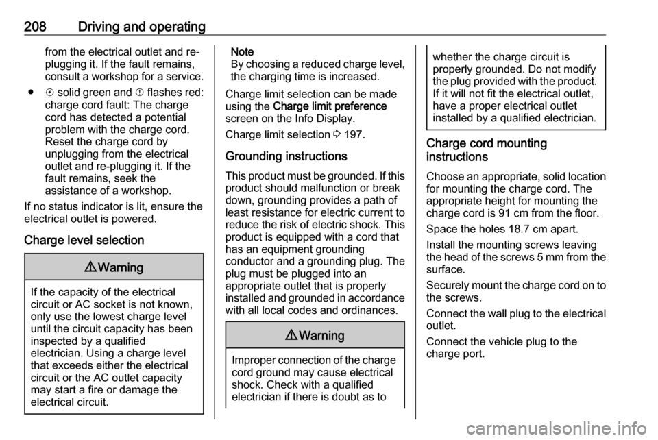
1. Vehicle plug
2. Protective cover
3. Status indicators
4. Wall plug
Charge cord status indicators
After plugging in the charge cord, it
will perform a quick self test.
Verify the charge cord status.
● c illuminates green and d is off,
the charge cord is ready to
charge the vehicle.
● c flashing green and d is off:
Electrical outlet / plug fault: The
charge cord has detected that the electrical outlet / plug
overheated. Use another
electrical outlet or have the
electrical outlet serviced by a
qualified electrician. Reset the
charge cord by unplugging the
charge cord from the electrical
outlet and re-plugging it.
● c is off and d flashes red:
Vehicle fault: The charge cord
ground-fault circuit interrupter
has tripped. Ensure that there is no physical damage to the
charge cord and that the vehicle
plug is seated completely and making a good connection. Reset
the charge cord by unplugging
Page 210 of 273

208Driving and operatingfrom the electrical outlet and re-
plugging it. If the fault remains,
consult a workshop for a service.
● c solid green and d flashes red:
charge cord fault: The charge cord has detected a potential
problem with the charge cord.
Reset the charge cord by
unplugging from the electrical
outlet and re-plugging it. If the fault remains, seek the
assistance of a workshop.
If no status indicator is lit, ensure the
electrical outlet is powered.
Charge level selection9 Warning
If the capacity of the electrical
circuit or AC socket is not known,
only use the lowest charge level
until the circuit capacity has been
inspected by a qualified
electrician. Using a charge level
that exceeds either the electrical
circuit or the AC outlet capacity
may start a fire or damage the
electrical circuit.
Note
By choosing a reduced charge level,
the charging time is increased.
Charge limit selection can be made
using the Charge limit preference
screen on the Info Display.
Charge limit selection 3 197.
Grounding instructions This product must be grounded. If this
product should malfunction or break
down, grounding provides a path of
least resistance for electric current to
reduce the risk of electric shock. This product is equipped with a cord that
has an equipment grounding
conductor and a grounding plug. The
plug must be plugged into an
appropriate outlet that is properly
installed and grounded in accordance
with all local codes and ordinances.9 Warning
Improper connection of the charge
cord ground may cause electrical
shock. Check with a qualified
electrician if there is doubt as to
whether the charge circuit is
properly grounded. Do not modify
the plug provided with the product.
If it will not fit the electrical outlet,
have a proper electrical outlet
installed by a qualified electrician.
Charge cord mounting
instructions
Choose an appropriate, solid location for mounting the charge cord. The
appropriate height for mounting the
charge cord is 91 cm from the floor.
Space the holes 18.7 cm apart.
Install the mounting screws leaving
the head of the screws 5 mm from the
surface.
Securely mount the charge cord on to
the screws.
Connect the wall plug to the electrical
outlet.
Connect the vehicle plug to the
charge port.
Page 221 of 273

Vehicle care219Wiper blade replacement
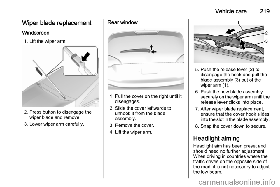
Windscreen 1. Lift the wiper arm.
2. Press button to disengage the wiper blade and remove.
3. Lower wiper arm carefully.
Rear window
1. Pull the cover on the right until it disengages.
2. Slide the cover leftwards to unhook it from the blade
assembly.
3. Remove the cover.
4. Lift the wiper arm.
5. Push the release lever (2) to disengage the hook and pull the
blade assembly (3) out of the
wiper arm (1).
6. Push the new blade assembly securely on the wiper arm until the
release lever clicks into place.
7. After wiper blade replacement, ensure that the cover hook slides
into the slot in the blade assembly.
8. Snap the cover down to secure.
Headlight aiming Headlight aim has been preset andshould need no further adjustment.
When driving in countries where the
traffic drives on the opposite side of the road, it is not necessary to adjust
the low beam.
Page 236 of 273

234Vehicle care
To access the tyre pressure page,
choose vehicle info menu via right
steering wheel buttons and press
{ or } to select tyre pressure.
To reset the system: ● Press and hold 9 until the tyre
pressure monitoring system asks
for a check.
● Press 9 again to confirm. The
vehicle honks twice.
System status and pressure warnings
are displayed by a message
indicating the corresponding tyre in
the Driver Information Centre.
The system considers the tyre
temperature for the warnings.
Temperature dependency 3 232.
A detected low tyre pressure
condition is indicated by the control
indicator w 3 80.
If w illuminates, stop as soon as
possible and inflate the tyres as
recommended 3 254.
After inflating, some driving may be
required to update the tyre pressure
values in the Driver Information
Centre. During this time w may
illuminate.
If w illuminates at lower temperatures
and extinguishes after driving, this
could be an indicator for approaching a low tyre pressure condition. Check
tyre pressure.
Vehicle messages 3 89.
If the tyre pressure must be reduced or increased, switch off vehicle.
Winter tyres or additional wheel sets
must be fitted with sensors, otherwise the system will not work and control
indicator w illuminates continuously.
The tyre pressure monitoring system
malfunction indicator is combined
with the low tyre pressure control
indicator. If the system detects a
malfunction, w will flash for approx.
1 minute and then remain
continuously illuminated. This
sequence will continue upon
subsequent vehicle start-ups as long
as the malfunction exists.
If the malfunction indicator w is
illuminated, the system may not be
able to detect or signal low tyre
pressure as intended. Tyre pressure
monitoring system malfunctions may
occur for a variety of reasons,
including the installation of
replacement or alternate tyres or wheels on the vehicle that prevent the
tyre pressure monitoring system from functioning properly. Always check
the tyre pressure monitoring system
malfunction control indicator w after
replacing one or more tyres or wheels
on your vehicle to ensure that the
Page 262 of 273

260Customer informationThis data includes, for example:● Vehicle status information (e.g. wheel rotation rate, speed,
movement delay, lateral
acceleration, "seatbelts
fastened" display),
● Ambient conditions (e.g. temperature, rain sensor,
distance sensor).
Most of this data is volatile and is
processed only in the vehicle itself, and not beyond the operating time.
Moreover, many control units include
data storage device (amongst others the vehicle key). This is used to allow
information to be documented
temporarily or permanently on vehicle condition, component stress,
maintenance requirements and
technical events and errors.
The following information, for
example, is stored:
● System component operating states (e.g. fill level, tyre
pressure, battery status),
● State of charge of the high voltage battery, estimated range
(in the case of electric vehicles),● Faults and defects in important system components (e.g. lights,
brakes),
● System reactions in special driving situations (e.g. triggeringof an airbag, actuation of the
stability control systems),
● Information on events damaging the vehicle.
In special cases (e.g. if the vehicle
has detected a malfunction), it may be
necessary to save data that would
otherwise just be volatile.
When you use services, the operating
data saved can be read together with the vehicle identification number andused if necessary. Staff working for
the service net-work (e.g. garages, manufacturers) or third parties (e.g.
breakdown services) can read the
data from the vehicle. Services
include repair services, maintenance
processes, warranty cases and
quality assurance measures.
Data is generally read via the OBD
(On-Board Diagnostics) port
prescribed by law in the vehicle. The operating data which has been read
out documents the technical conditionof the vehicle or individual
components and assists with fault
diagnosis, compliance with warranty
obligations and quality improvement.
This data, in particular information on component stress, technical events,
operator errors and other faults, is
transmitted to the manufacturer
where appropriate, together with the vehicle identification number. The
manufacturer is also subject to
product liability. The manufacturer
potentially also needs operating data
from vehicles for product recalls.
Fault memories in the vehicle can be
reset by a service company when
carrying out servicing or repairs.
Comfort and Infotainment
functions
Comfort settings and custom settings
can be stored in the vehicle and
changed at any time.