lock OPEL AMPERA E 2018 Manual user
[x] Cancel search | Manufacturer: OPEL, Model Year: 2018, Model line: AMPERA E, Model: OPEL AMPERA E 2018Pages: 267, PDF Size: 6.45 MB
Page 226 of 267

224Vehicle careEngine compartment fuse
box
The fuse box is located at the left front
side of the engine compartment.
To open the fuse block cover, press
the clip and remove the cover.
Page 229 of 267

Vehicle care227NumberUsage46Integrated chassis control
module47Headlight levelling device48Integrated chassis control
module49Interior rear view mirror50–51E-booster52Rear camera53Run / Crank54A/C control module55Rechargeable energy
storage system pump56–57Power electronics coolant
pump58Engine control module59Electric steering column
lockNumberUsage60HVAC electric heater61On-board charging module62Transmission range control
module 163Electric cooling fan64Engine control module65Auxiliary heater pump66Powertrain relay67Drive unit controller68Rear window defogger69Second run / Crank relay70A/C control module71–72Transmission range control
module73Single power inverter
module74–After having changed defective fuses,
close the fuse box cover and press
until it engages.
If the fuse box cover is not closed
correctly, malfunctions may occur.
Instrument panel fuse boxThe fuse box is located on the driver's
side behind a cover in the instrument
panel.
To open the compartment, compress
the locking tabs, fold cover down and remove.
Page 231 of 267

Vehicle care229The instrument panel fuse block is on
the left side of the instrument panel.
To access the fuses, open the fuse
panel door by pulling out.NumberUsage1Video processing module2Indicator light solar sensor3Side blind zone alert4Passive entry, passive start5Central gateway module6Body control module 47Body control module 38Body control module 29Body control module 110Trailer interface module 111Amplifier12Body control module 813Data link connector 114Automatic parking assist15Data link connector 2NumberUsage16Single power inverter
module 117Body control module 618Body control module 519–20–21–22–23USB24Wireless charging module25Reflected LED alert display26Heated steering wheel27–28Instrument cluster 229Trailer interface module 230Headlight levelling device31OnStar32–NumberUsage33Heating, ventilation, and air
conditioning module34–35Instrument panel cluster 136Regen on demand37–38–39–40–41–42–43Body control module 744Sensing and diagnostic
module45Front camera module46Vehicle integration control
module47Single power inverter
module 2
Page 232 of 267

230Vehicle careNumberUsage48Electric steering column
lock49Auxiliary jack50Steering wheel controls51Steering wheel controls
backlighting52Smartphone remote func‐
tion module53Auxiliary power outlet54–55Logistic56–57–58Logistics relay59–60Accessory / Retained
accessory power relay
To reinstall the door, insert the bottom tab first, then push the door back into its original location.
Vehicle tools
Tools
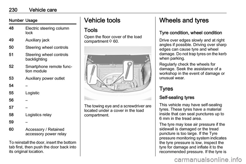
Open the floor cover of the load
compartment 3 60.
The towing eye and a screwdriver are
located under a cover in the load
compartment.
Wheels and tyres
Tyre condition, wheel condition Drive over edges slowly and at right
angles if possible. Driving over sharp
edges can cause tyre and wheel
damage. Do not trap tyres on the kerb when parking.
Regularly check the wheels for
damage. Seek the assistance of a
workshop in the event of damage or
unusual wear.
Tyres
Self-sealing tyres This vehicle may have self-sealing
tyres. These tyres have a material
inside that can seal punctures up to
6 mm in the tread area.
The tyre may lose air pressure if the
sidewall is damaged or the tread
puncture is too large. If the Tyre
pressure monitoring system indicates the tyre pressure is low, inspect thetyre for damage and inflate it to the
recommended pressure. If the tyre is
Page 237 of 267

Vehicle care235The available settings are:● Light for comfort pressure up to
three people.
● Eco for Eco pressure up to three
people.
● Max for full loading.
Auto learn function Each tyre pressure sensor has a
unique identification code. The
identification code must be matched
to a new wheel position after rotating
the wheels or exchanging the
complete wheel set and if one or more tyre pressure sensors were replaced.
After changing wheels, the vehicle
must be stationary for approx.
20 minutes before the system
recalculates. The following relearn
process takes up to 10 minutes of
driving with a minimum speed of
20 km/h. In this event, w can be
displayed or pressure values can
swap in the Driver Information Centre.
If problems occur during the relearn
process, a warning message will be
displayed in the Driver Information
Centre.Tread depth
Check tread depth at regular
intervals.
Tyres should be replaced for safety
reasons at a tread depth of 2-3 mm
(4 mm for winter tyres).
For safety reasons it is recommended
that the tread depth of the tyres on
one axle should not vary by more than 2 mm.
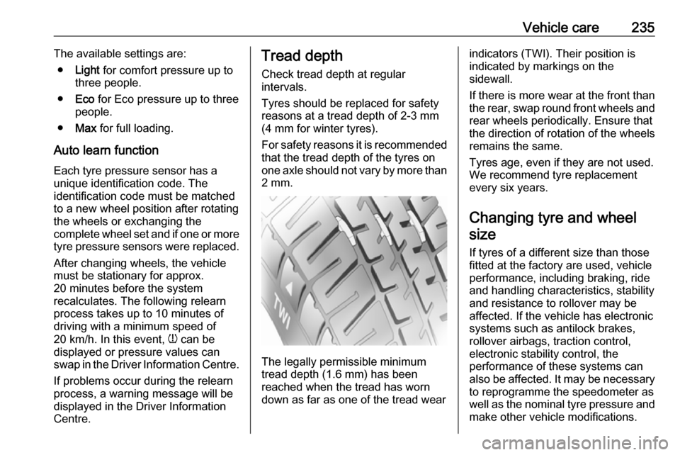
The legally permissible minimum
tread depth (1.6 mm) has been
reached when the tread has worn
down as far as one of the tread wear
indicators (TWI). Their position is
indicated by markings on the
sidewall.
If there is more wear at the front than
the rear, swap round front wheels and rear wheels periodically. Ensure that
the direction of rotation of the wheels
remains the same.
Tyres age, even if they are not used.
We recommend tyre replacement
every six years.
Changing tyre and wheel size
If tyres of a different size than those
fitted at the factory are used, vehicle
performance, including braking, ride
and handling characteristics, stability
and resistance to rollover may be
affected. If the vehicle has electronic
systems such as antilock brakes,
rollover airbags, traction control,
electronic stability control, the
performance of these systems can
also be affected. It may be necessary
to reprogramme the speedometer as
well as the nominal tyre pressure and
make other vehicle modifications.
Page 238 of 267

236Vehicle careAfter converting to a different tyre
size, have the label with tyre
pressures replaced.
Tyre pressure monitoring system 3 233.9 Warning
The use of unsuitable tyres or
wheels may lead to accidents and will invalidate the vehicle
operating permit.
Wheel covers
Wheel covers and tyres that are
factory approved for the respective
vehicle and comply with all of the
relevant wheel and tyre combination
requirements must be used.
If the wheel covers and tyres used are
not factory approved, the tyres must
not have a rim protection ridge.
Wheel covers must not impair brake
cooling.
9 Warning
Use of unsuitable tyres or wheel
covers could lead to sudden
pressure loss and thereby
accidents.
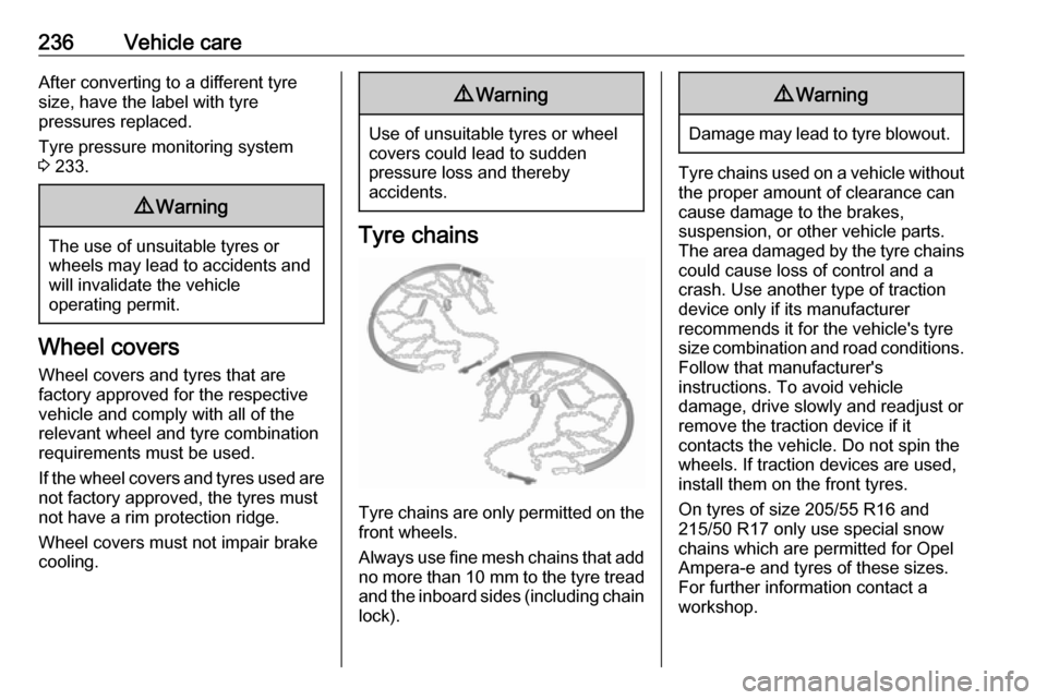
Tyre chains
Tyre chains are only permitted on the
front wheels.
Always use fine mesh chains that add no more than 10 mm to the tyre tread
and the inboard sides (including chain lock).
9 Warning
Damage may lead to tyre blowout.
Tyre chains used on a vehicle without
the proper amount of clearance can
cause damage to the brakes,
suspension, or other vehicle parts.
The area damaged by the tyre chains could cause loss of control and a
crash. Use another type of traction
device only if its manufacturer
recommends it for the vehicle's tyre size combination and road conditions.
Follow that manufacturer's
instructions. To avoid vehicle
damage, drive slowly and readjust or
remove the traction device if it
contacts the vehicle. Do not spin the
wheels. If traction devices are used,
install them on the front tyres.
On tyres of size 205/55 R16 and 215/50 R17 only use special snow
chains which are permitted for Opel
Ampera-e and tyres of these sizes. For further information contact a
workshop.
Page 241 of 267

Vehicle care239Route the leads so that they cannot
catch on rotating parts in the engine
compartment.
To start the vehicle: 1. Start the engine of the vehicle providing the jump.
2. After five minutes, press POWER m to switch on the
vehicle.
After the instrument cluster
initialises, the vehicle will use
power from the high voltage
battery to charge the 12 V vehicle
battery.
3. Switch on electrical consumers (e.g. headlights, heated rear
window) of the vehicle receiving
the jump start.
4. Reverse above sequence exactly when removing leads.Towing
Towing the vehicleCaution
Incorrect towing of a disabled
vehicle may cause damage to the
vehicle. The disabled vehicle
should only be towed on a flatbed
car carrier.
Ensure the vehicle is only towed
by well trained technicians.
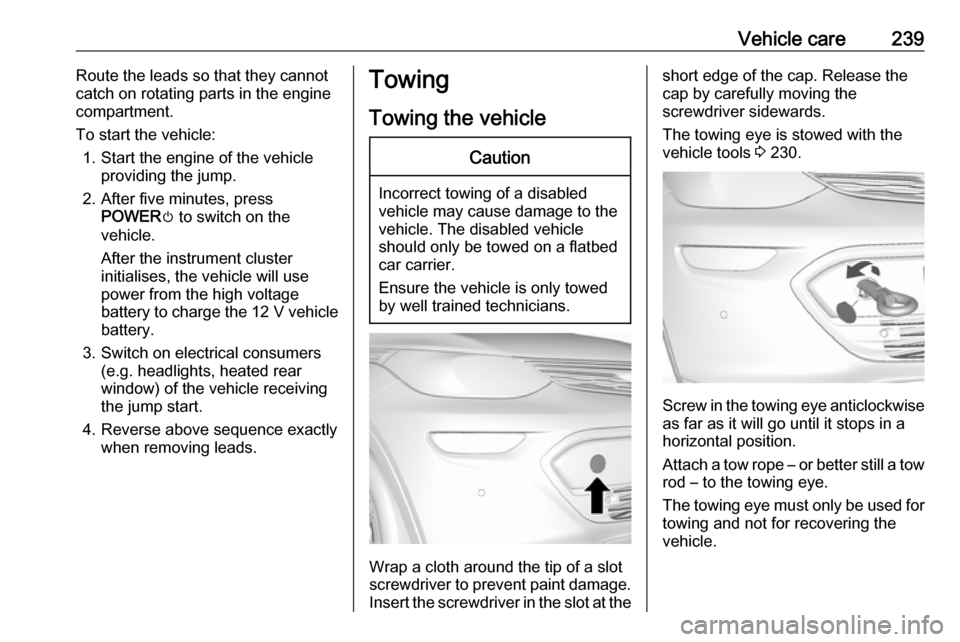
Wrap a cloth around the tip of a slot
screwdriver to prevent paint damage. Insert the screwdriver in the slot at the
short edge of the cap. Release the
cap by carefully moving the
screwdriver sidewards.
The towing eye is stowed with the vehicle tools 3 230.
Screw in the towing eye anticlockwise
as far as it will go until it stops in a
horizontal position.
Attach a tow rope – or better still a tow
rod – to the towing eye.
The towing eye must only be used for
towing and not for recovering the
vehicle.
Page 242 of 267

240Vehicle careSwitch on the vehicle to release
steering wheel lock and to permit
operation of brake lights, horn and
windscreen wiper.
Shift the selector lever of the electric
drive unit into N.
Release the electric parking brake.Caution
Drive slowly. Do not drive jerkily.
Excessive tractive force can
damage the vehicle.
When the vehicle is not running, considerably more force is needed to
brake and steer.
To prevent the entry of exhaust gases from the towing vehicle, switch on the
air recirculation and close the
windows.
Seek the assistance of a workshop.
After towing, unscrew the towing eye.
Insert cap at the bottom and close.
Towing another vehicle
The vehicle is neither designed nor
intended to tow a trailer or another
vehicle.Appearance care
Exterior care
Locks The locks are lubricated at the factoryusing a high quality lock cylinder
grease. Use de-icing agent only when
absolutely necessary, as this has a
degreasing effect and impairs lock function. After using a de-icing agent, have the locks regreased by a
workshop.
Washing The paintwork of your vehicle is
exposed to environmental influences.
Wash and wax your vehicle regularly. When using automatic vehicle
washes, select a programme that
includes waxing.
Do not apply waxes or polishes to uncoated plastic, vinyl, rubber,
decals, simulated wood, or flat paint
as damage can occur.
Page 259 of 267

Customer information257Vehicle data recording
and privacy
Event data recorders Data storage modules in the
vehicle
A large number of electronic
components of your vehicle contain
data storage modules temporarily or
permanently storing technical data
about the condition of the vehicle,
events and errors. In general, this
technical information documents the
condition of parts, modules, systems
or the environment:
● operating conditions of system components (e.g. filling levels)
● status messages of the vehicle and its single components (e.g.
number of wheel revolutions / rotational speed, deceleration,
lateral acceleration)
● dysfunctions and defects in important system components● vehicle reactions in particulardriving situations ( e.g. inflation of
an airbag, activation of the
stability regulation system)
● environmental conditions (e.g. temperature)
These data are exclusively technical
and help identifying and correcting
errors as well as optimising vehicle
functions.
Motion profiles indicating travelled
routes cannot be created with these
data.
If services are used (e.g. repair
works, service processes, warranty
cases, quality assurance),
employees of the service network
(manufacturer included) are able to
read out this technical information
from the event and error data storage
modules applying special diagnostic
devices. If required, you will receive
further information at these
workshops. After an error has been
corrected, the data are deleted from
the error storage module or they are
constantly overwritten.When using the vehicle, situations
may occur in which these technical
data related to other information
(accident report, damages on the
vehicle, witness statements etc.) may
be associated with a specific person - possibly, with the assistance of an
expert.
Additional functions contractually
agreed upon with the client (e.g.
vehicle location in emergency cases)
allow the transmission of particular
vehicle data from the vehicle.
Radio Frequency
Identification (RFID)
RFID technology is used in some
vehicles for functions such as tyre
pressure monitoring and immobiliser
system. It is also used in connection
with conveniences such as radio
remote controls for door locking /
unlocking and starting, and in-vehicle transmitters for garage door openers.
RFID technology in Opel vehicles
does not use or record personal
information or link with any other Opel system containing personal
information.
Page 260 of 267

258IndexAAccessories and vehicle modifications .......................... 209
Activating Bluetooth music .........127
Activating phone .........................136
Activating radio ........................... 119
Activating USB audio ..................127
Activating USB movie .................130
Activating USB picture ................129
Active emergency braking ..........168
Adjustable air vents ...................145
Airbag and belt tensioners ...........78
Airbag deactivation ................49, 78
Airbag label................................... 45 Airbag system .............................. 45
Air conditioning regular operation ................................ 146
Air intake .................................... 146
Air vents...................................... 145
Antilock brake system ................ 157
Antilock brake system (ABS) .......79
Anti-theft alarm system ................29
Anti-theft locking system .............. 29
Appearance care ........................240
Armrest ................................... 40, 42
Armrest storage ........................... 58
Audio files ................................... 125
Automatic anti-dazzle ..................33
Automatic light control .................99
Automatic locking ........................25Auto volume................................ 115
AUX Connecting device ..................125
General information ................125
B Basic operation ........................... 112
Battery discharge protection ......104
Battery gauge ............................... 74
Battery voltage ............................. 90
Belts.............................................. 42
Bluetooth Bluetooth connection ..............134
Bluetooth music menu ............127
Connecting device ..................125
General information ................125
Pairing ..................................... 134
Phone ...................................... 136
Bluetooth connection ..................134
Bonnet ....................................... 212
Brake fluid .......................... 215, 245
Brakes ............................... 157, 215
Brake system ............................... 79
Breakdown.................................. 239
BringGo ...................................... 131
Bulb replacement ....................... 219
C Call Functions during a call ............136
Incoming call ........................... 136