instrument panel OPEL AMPERA E 2019 Manual user
[x] Cancel search | Manufacturer: OPEL, Model Year: 2019, Model line: AMPERA E, Model: OPEL AMPERA E 2019Pages: 271, PDF Size: 6.7 MB
Page 196 of 271

194Driving and operating
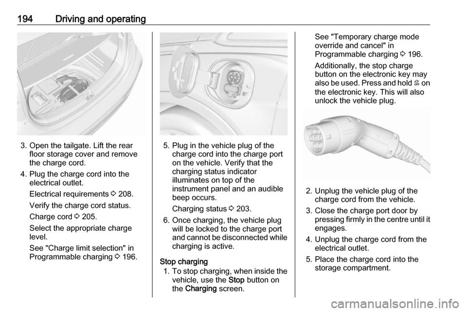
3. Open the tailgate. Lift the rearfloor storage cover and remove
the charge cord.
4. Plug the charge cord into the electrical outlet.
Electrical requirements 3 208.
Verify the charge cord status.
Charge cord 3 205.
Select the appropriate charge
level.
See "Charge limit selection" in
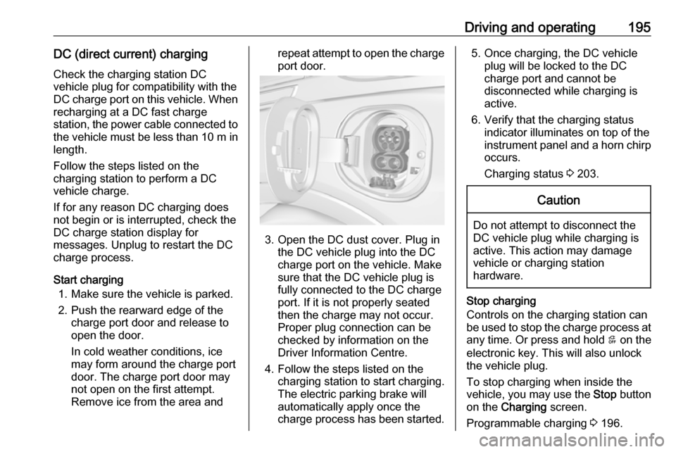
Programmable charging 3 196.5. Plug in the vehicle plug of the
charge cord into the charge port
on the vehicle. Verify that the
charging status indicator
illuminates on top of the
instrument panel and an audible
beep occurs.
Charging status 3 203.
6. Once charging, the vehicle plug will be locked to the charge port
and cannot be disconnected while
charging is active.
Stop charging 1. To stop charging, when inside the
vehicle, use the Stop button on
the Charging screen.
See "Temporary charge mode
override and cancel" in
Programmable charging 3 196.
Additionally, the stop charge button on the electronic key may
also be used. Press and hold 5 on
the electronic key. This will also
unlock the vehicle plug.
2. Unplug the vehicle plug of the charge cord from the vehicle.
3. Close the charge port door by pressing firmly in the centre until it
engages.
4. Unplug the charge cord from the electrical outlet.
5. Place the charge cord into the storage compartment.
Page 197 of 271

Driving and operating195DC (direct current) chargingCheck the charging station DC
vehicle plug for compatibility with the
DC charge port on this vehicle. When
recharging at a DC fast charge
station, the power cable connected to the vehicle must be less than 10 m in
length.
Follow the steps listed on the
charging station to perform a DC
vehicle charge.
If for any reason DC charging does
not begin or is interrupted, check the
DC charge station display for
messages. Unplug to restart the DC
charge process.
Start charging 1. Make sure the vehicle is parked.
2. Push the rearward edge of the charge port door and release to
open the door.
In cold weather conditions, ice
may form around the charge port
door. The charge port door may
not open on the first attempt.
Remove ice from the area andrepeat attempt to open the charge
port door.
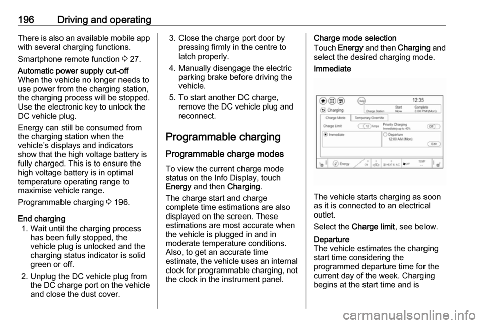
3. Open the DC dust cover. Plug in the DC vehicle plug into the DC
charge port on the vehicle. Make
sure that the DC vehicle plug is
fully connected to the DC charge
port. If it is not properly seated
then the charge may not occur.
Proper plug connection can be
checked by information on the
Driver Information Centre.
4. Follow the steps listed on the charging station to start charging.
The electric parking brake will
automatically apply once the
charge process has been started.
5. Once charging, the DC vehicle plug will be locked to the DC
charge port and cannot be
disconnected while charging is
active.
6. Verify that the charging status indicator illuminates on top of the
instrument panel and a horn chirp occurs.
Charging status 3 203.Caution
Do not attempt to disconnect the
DC vehicle plug while charging is
active. This action may damage vehicle or charging station
hardware.
Stop charging
Controls on the charging station can
be used to stop the charge process at any time. Or press and hold 5 on the
electronic key. This will also unlock
the vehicle plug.
To stop charging when inside the
vehicle, you may use the Stop button
on the Charging screen.
Programmable charging 3 196.
Page 198 of 271

196Driving and operatingThere is also an available mobile appwith several charging functions.
Smartphone remote function 3 27.Automatic power supply cut-off
When the vehicle no longer needs to
use power from the charging station,
the charging process will be stopped.
Use the electronic key to unlock the
DC vehicle plug.
Energy can still be consumed from
the charging station when the
vehicle’s displays and indicators
show that the high voltage battery is
fully charged. This is to ensure the
high voltage battery is in optimal
temperature operating range to
maximise vehicle range.
Programmable charging 3 196.
End charging
1. Wait until the charging process has been fully stopped, the
vehicle plug is unlocked and the
charging status indicator is solid
green or off.
2. Unplug the DC vehicle plug from the DC charge port on the vehicle
and close the dust cover.
3. Close the charge port door by pressing firmly in the centre to
latch properly.
4. Manually disengage the electric parking brake before driving the
vehicle.
5. To start another DC charge, remove the DC vehicle plug and
reconnect.
Programmable charging
Programmable charge modes To view the current charge mode
status on the Info Display, touch Energy and then Charging.
The charge start and charge
complete time estimations are also
displayed on the screen. These
estimations are most accurate when
the vehicle is plugged in and in
moderate temperature conditions.
Also, to get an accurate time
estimate, the vehicle uses an internal clock for programmable charging, notthe clock in the instrument panel.Charge mode selection
Touch Energy and then Charging and
select the desired charging mode.Immediate
The vehicle starts charging as soon
as it is connected to an electrical outlet.
Select the Charge limit , see below.
Departure
The vehicle estimates the charging start time considering the
programmed departure time for the
current day of the week. Charging
begins at the start time and is
Page 205 of 271

Driving and operating203● Touch Cancel to make no
changes.
● Touch Remove to clear the
location and turn location
based charging off.
Charging interrupted or
overridden pop-up
The Charging override / interruption
occurred pop-up will appear if any of
the following conditions occur:
● The charging settings have been
modified via OnStar through the
website or the mobile app. For
example, the departure time
tables, the rate tables, or the
charge mode were updated using
the customer website (available
in select regions).
● There was an unintended loss of AC power during the plug-in
charge event. For example, there was a power outage or the
charge cord was unplugged from the wall.Programmable charging disabled
When the programmable charging
system is disabled, the Unable to
charge screen will be displayed.
Programmed charging override
To temporarily override a delayed charge event, unplug the charge cord from the charge port and then plug it
back in within 5 seconds. A single
horn chirp will sound and charging will begin immediately.
To cancel a temporary override,
unplug the charge cord, wait for
10 seconds, and then plug the charge cord back in. A double horn chirp will
sound and charging will be delayed.
Programmable charging 3 196.
Charging status
The vehicle has a charging status
indicator at the centre of the
instrument panel near the
windscreen. When the vehicle is
plugged in and the vehicle power is
off, the charging status indicator
indicates the following:
Page 211 of 271

Vehicle care209Vehicle careGeneral Information...................209
Accessories and vehicle modifications .......................... 209
Lifting the vehicle .....................210
Vehicle storage ........................210
End-of-life vehicle recovery .....211
Vehicle checks ........................... 211
Performing work ......................211
Bonnet ..................................... 212
Cooling system ........................213
Washer fluid ............................ 215
Brakes ..................................... 215
Brake fluid ............................... 215
Vehicle battery ......................... 216
Wiper blade replacement ........218
Headlight aiming ......................218
Bulb replacement .......................219
Halogen bulbs ......................... 219
Xenon headlights .....................219
Front turn lights .......................219
Tail lights ................................. 220
Side turn lights ......................... 220
Number plate light ...................221Electrical system ........................222
High voltage devices and wiring ...................................... 222
Electrical system overload .......222
Fuses ....................................... 222
Engine compartment fuse box . 224
Instrument panel fuse box .......227
Vehicle tools .............................. 230
Tools ........................................ 230
Wheels and tyres .......................230
Tyres ....................................... 230
Winter tyres ............................. 231
Tyre designations ....................231
Tyre pressure .......................... 231
Tyre pressure monitoring system .................................... 232
Tread depth ............................. 234
Changing tyre and wheel size . 235
Wheel covers ........................... 235
Tyre chains .............................. 236
Tyre repair kit .......................... 236
Jump starting ............................. 240
Towing ....................................... 242
Towing the vehicle ...................242
Towing another vehicle ...........243
Appearance care .......................243
Exterior care ............................ 243
Interior care ............................. 245General Information
Accessories and vehiclemodifications
We recommend the use of genuine
parts and accessories and factory
approved parts specific for your
vehicle type. We cannot assess or
guarantee reliability of other products - even if they have a regulatory or
otherwise granted approval.
Any modification, conversion or other
changes made to standard vehicle
specifications (including, without
limitation, software modifications,
modifications of the electronic control units) may invalidate the warranty
offered by Opel. Furthermore, such
changes may affect driver assistance
systems and energy consumption.
They may also invalidate the vehicle
operating permit.Caution
When transporting the vehicle on
a train or on a recovery vehicle, the
mud flaps might be damaged.
Page 224 of 271

222Vehicle careElectrical systemHigh voltage devices andwiring9 Warning
Exposure to high voltage may
cause shock, burns, and even
death. The high voltage
components in the vehicle should
only be serviced by specially
trained technicians.
High voltage components are
identified by labels. Do not
remove, open, take apart, or
modify these components. High
voltage cable or wiring has orange covering. Do not probe, tamper
with, cut, or modify high voltage
cable or wiring.
Electrical system overload
The vehicle has fuses and circuit
breakers to protect against an
electrical system overload.
If the current electrical load is too
heavy, the circuit breaker will open
and close, protecting the circuit until
the current load returns to normal or the problem is fixed. This greatly
reduces the chance of circuit
overload and fire caused by electrical
problems.
Fuses and circuit breakers protect the
following parts in the vehicle:
● Headlight wiring
● Windscreen wiper motor
● Power windows and other power accessories
Headlight wiring An electrical overload may cause the
lights to go on and off or in some
cases to remain off. In this case, have
the headlight wiring checked
immediately by a workshop.
Windscreen wipers
If the wiper motor overheats due to
blockage from heavy snow or ice, the windscreen wipers will stop until themotor has cooled down and the wiper
control has been turned off. Afterremoval of the blockage, the wiper
motor will restart when moving the
wiper control to the desired operating
position.
Although the circuit is protected from
electrical overload, mechanical
overload due to heavy snow or ice
may cause wiper linkage damage.
Always clear ice and heavy snow
from the windscreen before using the windscreen wipers. If the overload is
caused by an electrical problem and
not snow or ice, it must be serviced.
Fuses
Data on the replacement fuse must match the data on the defective fuse.
There are two fuse boxes in the
vehicle:
● at the front left side of the engine
compartment
● at the left side of the instrument panel
Before replacing a fuse, turn off the
respective switch and the vehicle.
Page 229 of 271

Vehicle care227NumberUsage45Vehicle integration control
module46Integrated chassis control
module47Headlight levelling device48Integrated chassis control
module49Interior rear view mirror50–51E-booster52Rear camera53–54A/C control module55Rechargeable energy
storage system pump56–57Power electronics coolant
pump58Engine control moduleNumberUsage59Electric steering column
lock60HVAC electric heater61On-board charging module62Transmission range control
module 163Electric cooling fan64Engine control module65Auxiliary heater pump66–67Drive unit controller68Rear window defogger69–70A/C control module71–72Transmission range control
moduleNumberUsage73Single power inverter
module74–
After having changed defective fuses,
close the fuse box cover and press
until it engages.
If the fuse box cover is not closed
correctly, malfunctions may occur.
Instrument panel fuse boxThe fuse box is located on the driver's
side behind a cover in the instrument
panel.
Page 230 of 271

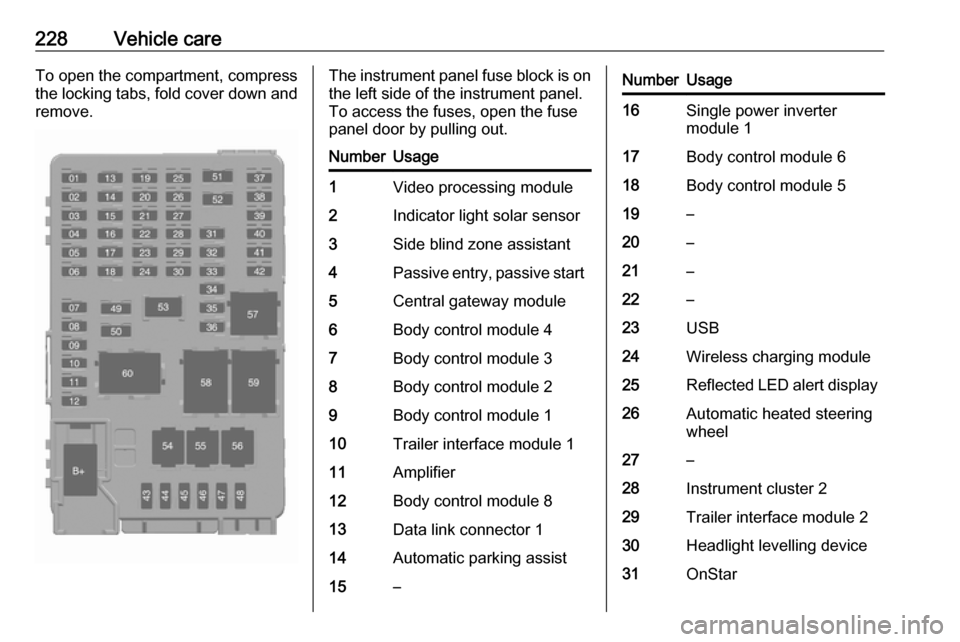
228Vehicle careTo open the compartment, compress
the locking tabs, fold cover down and remove.The instrument panel fuse block is on the left side of the instrument panel.
To access the fuses, open the fuse
panel door by pulling out.NumberUsage1Video processing module2Indicator light solar sensor3Side blind zone assistant4Passive entry, passive start5Central gateway module6Body control module 47Body control module 38Body control module 29Body control module 110Trailer interface module 111Amplifier12Body control module 813Data link connector 114Automatic parking assist15–NumberUsage16Single power inverter
module 117Body control module 618Body control module 519–20–21–22–23USB24Wireless charging module25Reflected LED alert display26Automatic heated steering
wheel27–28Instrument cluster 229Trailer interface module 230Headlight levelling device31OnStar
Page 231 of 271

Vehicle care229NumberUsage32–33Heating, ventilation, and air
conditioning module34–35Instrument panel cluster 136Radio37–38–39–40–41–42–43Body control module 744Sensing and diagnostic
module45Front camera module46Vehicle integration control
moduleNumberUsage47Single power inverter
module 248Electric steering column
lock49Auxiliary jack50Steering wheel controls51Steering wheel controls
backlighting52Smartphone remote func‐
tion module53Auxiliary power outlet54–55Logistic56–57–58–59–60–To reinstall the door, insert the bottom tab first, then push the door back into its original location.
Page 247 of 271

Vehicle care245Bitumen / rubber materials could
damage the PVC coating. Have
underbody work carried out by a
workshop.
Before and after winter, wash the
underbody and have the protective
wax coating checked.
Interior care
Interior and upholstery
Only clean the vehicle interior,
including the instrument panel fascia
and panelling, with a dry cloth or
interior cleaner.
Clean the leather upholstery with
clear water and a soft cloth. In case of
heavy soiling, use leather care.
The instrument cluster and the
displays should only be cleaned using a soft damp cloth. If necessary use a
weak soap solution.
Do not spray cleaners directly on any
switches or controls.
Clean fabric upholstery with a
vacuum cleaner and brush. Remove
stains with an upholstery cleaner.Clothing fabrics may not be
colourfast. This could cause visible
discolourations, especially on light-
coloured upholstery. Removable
stains and discolourations should be
cleaned as soon as possible.
Clean seat belts with lukewarm water or interior cleaner.Caution
Close Velcro fasteners as open
Velcro fasteners on clothing could damage seat upholstery.
The same applies to clothing with
sharp-edged objects, like zips or
belts or studded jeans.
Plastic and rubber parts
Plastic and rubber parts can be
cleaned with the same cleaner as
used to clean the body. Use interior cleaner if necessary. Do not use any
other agent. Avoid solvents and petrol
in particular. Do not use high-
pressure jet cleaners.