ESP OPEL AMPERA E 2019 Manual user
[x] Cancel search | Manufacturer: OPEL, Model Year: 2019, Model line: AMPERA E, Model: OPEL AMPERA E 2019Pages: 271, PDF Size: 6.7 MB
Page 193 of 271
Driving and operating191Activation
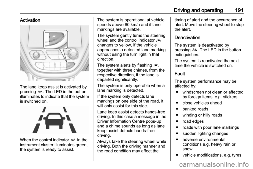
The lane keep assist is activated by
pressing a. The LED in the button
illuminates to indicate that the system
is switched on.
When the control indicator a in the
instrument cluster illuminates green,
the system is ready to assist.
The system is operational at vehicle
speeds above 60 km/h and if lane
markings are available.
The system gently turns the steering
wheel and the control indicator a
changes to yellow, if the vehicle
approaches a detected lane marking
without using the turn light in that
direction.
The system alerts by flashing a
together with three chimes, from the respective direction, if the lane is
departed significantly.
The system is only operable when a
lane marking is detected.
If the system only detects lane
markings on one side of the road, it
will only assist for this side.
Lane keep assist detects hands-free
driving. In this case a message in the
Driver Information Centre pops-up
and a chime sounds as long as lane
keep assist detects hands-free
driving.
Always take the steering wheel while
driving. Both the driving manner and
the road condition may affect thetiming of alert and the occurrence of
alert. Move the steering wheel to stop
the alert.
Deactivation The system is deactivated by
pressing a. The LED in the button
extinguishes.
The system is reactivated the next
time the vehicle is switched on.
Fault The system performance may beaffected by:
● windscreen not clean or affected by foreign items, e.g. stickers
● close vehicles ahead
● banked roads
● winding or hilly roads
● road edges
● roads with poor lane markings
● sudden lighting changes
● adverse environmental conditions e.g. heavy rain or
snow
● vehicle modifications, e.g. tyres
Page 194 of 271

192Driving and operatingSwitch off the system if the system is
disturbed by tar marks, shadows,
road cracks, temporary or
construction lane markings, or other
road imperfections.9 Warning
Always keep your attention on the
road and maintain proper vehicle
position within the lane, otherwise
vehicle damage, injury or death
could occur.
The system does not detect
pedestrians, cyclists or animals on
the road. Steer the vehicle
manually to avoid injuries and
deaths.
Lane keep assist does not
continuously steer the vehicle.
The system may not keep the
vehicle in the lane or give an alert, even if a lane marking is detected.
The steering of the lane keep
assist may not be sufficient to
avoid a lane departure.
The system may not detect hands-
off driving due to external
influences (road condition and
surface, weather etc). The driver
has full responsibility to control the vehicle and is always required tokeep the hands on the steeringwheel while driving.
Using the system while driving on
slippery roads could cause loss of control of the vehicle and a crash.
Switch off the system.Charging
This section explains the process of
charging the vehicle's high voltage
battery. Do not allow the vehicle to
remain in places with extremes of
temperature for long periods without
being driven or plugged in.
It is recommended to keep the vehicle
plugged in, even if fully charged, to
keep the high voltage battery
temperature ready for the next drive.
The vehicle must be plugged in when
the temperatures are below -25 °C, to operate properly and to maximise
high voltage battery life.
However, we recommend plugging in
the vehicle when temperatures drop
below 0 °C or raise above 32 °C.
When using the portable charge cord, it will take approximately 33 hours to
charge the vehicle with the 10 A
setting.
When using a 230 V charging station, it will take approximately 10 hours to
charge the vehicle with the 32 A
setting.
Page 195 of 271

Driving and operating193Charge times will vary based on high
voltage battery condition and outside
temperature. There are three ways to
programme how the vehicle is
charged.
Programmable charging 3 196.
The charging system may run fans
and pumps resulting in noises coming from the vehicle while it is turned off.
Additional clicking sounds may be
caused by the electrical devices used
while charging.
While the charge cord is plugged into
the vehicle, the vehicle cannot be
driven.
When to charge When the high voltage battery is
getting low, charging messages may
be displayed.
The Charge vehicle soon message
indicates that the driving range is low
and the vehicle needs to be charged
soon. As the charge level drops, the
Propulsion power is reduced
message is displayed and the
accelerator pedal response is
reduced. In addition, the remainingrange value will change to Low
indicating the vehicle should be
charged immediately.
When the energy is fully depleted, the
Out of power. Charge vehicle now
message is displayed and the vehicle slows to a stop. Brake and steering
assist will still operate. Once the
vehicle has stopped, switch off the
vehicle.
AC (alternating current) charging
Start charging
A portable charge cord used to
charge the vehicle high voltage
battery is stored under the rear floor
storage cover in the load
compartment.
1. Shift into P (Park) and switch off
the vehicle.
2. Push the rearward edge of the charge port door in and release toopen the door.
In cold weather conditions, ice
may form around the charge port
door. Remove ice from the area
before attempting to open or close
the charge port door.
Page 215 of 271
Vehicle care2133. Release the bonnet support fromits retainer above the radiator
support and place it securely into
the slotted retainer in the bonnet.
Closing Before closing the bonnet, press the
support into the holder.
Lower the bonnet and let it fall into the
latch from a low height (20-25 cm).
Check that the bonnet is engaged.Caution
Do not press the bonnet into the
latch to avoid dents.
Cooling system
The vehicle has three different
cooling systems.
Regularly check the coolant level of
the respective cooling systems and
have the cause of a possible coolant
loss remedied by a workshop.
Caution
Make sure that you never run the
vehicle with insufficient coolant.
A low coolant level can cause
damage to the vehicle.
Heater cooling system
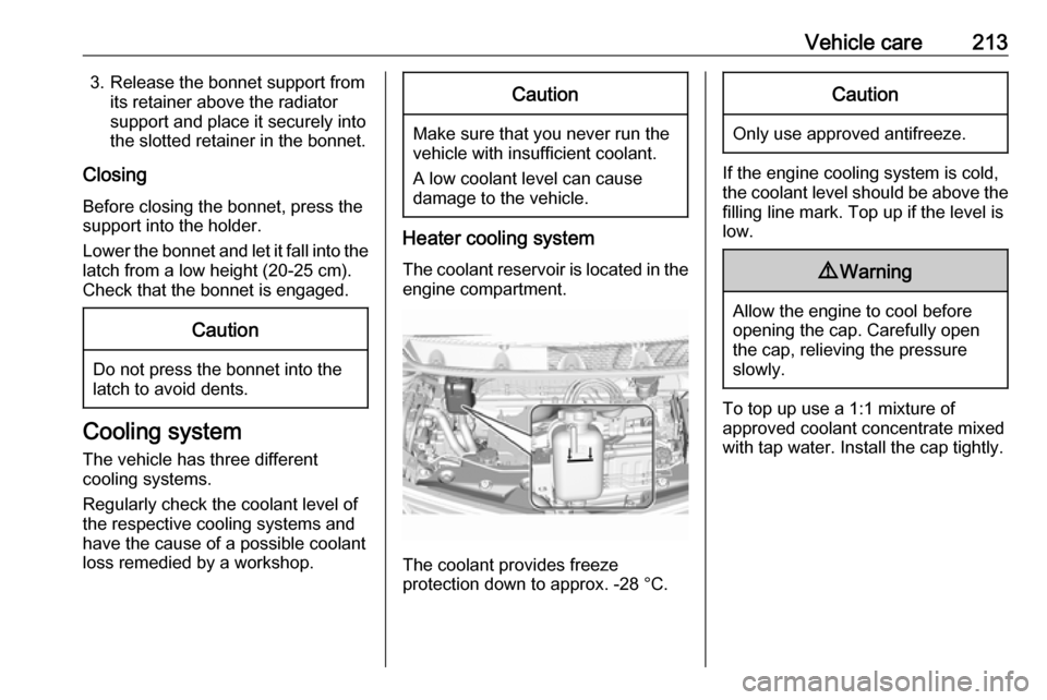
The coolant reservoir is located in the engine compartment.
The coolant provides freeze
protection down to approx. -28 °C.
Caution
Only use approved antifreeze.
If the engine cooling system is cold,
the coolant level should be above the
filling line mark. Top up if the level is
low.
9 Warning
Allow the engine to cool before
opening the cap. Carefully open
the cap, relieving the pressure
slowly.
To top up use a 1:1 mixture of
approved coolant concentrate mixed
with tap water. Install the cap tightly.
Page 221 of 271
Vehicle care219If the vehicle is damaged in a crash,
the headlight aim may be affected. If
adjustment to the low beam is
necessary, seek the assistance of a
workshop.Bulb replacement
Switch off the vehicle and the relevant
light.
Only hold a new bulb at the base. Do
not touch the bulb glass with bare
hands.
Use only the same bulb type for
replacement.
Replace headlight bulbs from within
the engine compartment.
Bulb check After a bulb replacement, switch on
the vehicle, operate and check the
lights.
Halogen bulbs9 Warning
Halogen bulbs have pressurised
gas inside and can burst if you
drop or scratch the bulb. You or others could be injured. Be sure to read and follow the instructions onthe bulb package.
Xenon headlights9 Danger
Xenon headlights work under
extremely high electrical voltage.
Do not touch. Have bulbs replaced by a workshop.
Bulbs for front turn lights and
corner lighting can be changed.
Sidelight / Daytime running lights are
designed as Light Emitting Diodes
(LEDs) and cannot be replaced.
Front turn lights Each turn light is accessible from
behind via the respective wheel
house:
Page 222 of 271
220Vehicle care
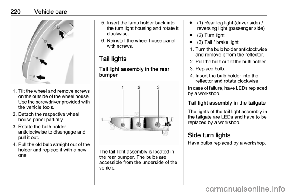
1.Tilt the wheel and remove screws
on the outside of the wheel house.
Use the screwdriver provided with the vehicle tools.
2. Detach the respective wheel house panel partially.
3. Rotate the bulb holder anticlockwise to disengage and
pull it out.
4. Pull the old bulb straight out of the
holder and replace it with a new
one.
5. Insert the lamp holder back into the turn light housing and rotate it
clockwise.
6. Reinstall the wheel house panel with screws.
Tail lights Tail light assembly in the rear
bumper
The tail light assembly is located in
the rear bumper. The bulbs are
accessible from the underside of the
vehicle.
● (1) Rear fog light (driver side) / reversing light (passenger side)
● (2) Turn light
● (3) Tail / brake light 1. Turn the bulb holder anticlockwise
and remove it from the reflector.
2. Pull the bulb out of the bulb holder.
3. Replace bulb.
4. Insert the bulb holder into the reflector and rotate clockwise.
In case of failure, have LEDs replaced by a workshop.
Tail light assembly in the tailgate The lights of the tail light assembly in
the tailgate are LEDs and have to be
replaced by a workshop.
Side turn lights Have bulbs replaced by a workshop.
Page 224 of 271

222Vehicle careElectrical systemHigh voltage devices andwiring9 Warning
Exposure to high voltage may
cause shock, burns, and even
death. The high voltage
components in the vehicle should
only be serviced by specially
trained technicians.
High voltage components are
identified by labels. Do not
remove, open, take apart, or
modify these components. High
voltage cable or wiring has orange covering. Do not probe, tamper
with, cut, or modify high voltage
cable or wiring.
Electrical system overload
The vehicle has fuses and circuit
breakers to protect against an
electrical system overload.
If the current electrical load is too
heavy, the circuit breaker will open
and close, protecting the circuit until
the current load returns to normal or the problem is fixed. This greatly
reduces the chance of circuit
overload and fire caused by electrical
problems.
Fuses and circuit breakers protect the
following parts in the vehicle:
● Headlight wiring
● Windscreen wiper motor
● Power windows and other power accessories
Headlight wiring An electrical overload may cause the
lights to go on and off or in some
cases to remain off. In this case, have
the headlight wiring checked
immediately by a workshop.
Windscreen wipers
If the wiper motor overheats due to
blockage from heavy snow or ice, the windscreen wipers will stop until themotor has cooled down and the wiper
control has been turned off. Afterremoval of the blockage, the wiper
motor will restart when moving the
wiper control to the desired operating
position.
Although the circuit is protected from
electrical overload, mechanical
overload due to heavy snow or ice
may cause wiper linkage damage.
Always clear ice and heavy snow
from the windscreen before using the windscreen wipers. If the overload is
caused by an electrical problem and
not snow or ice, it must be serviced.
Fuses
Data on the replacement fuse must match the data on the defective fuse.
There are two fuse boxes in the
vehicle:
● at the front left side of the engine
compartment
● at the left side of the instrument panel
Before replacing a fuse, turn off the
respective switch and the vehicle.
Page 233 of 271

Vehicle care231The following applies to tyres fitted
opposing the rolling direction:
● Driveability may be affected.● Do not drive faster than 80 km/h.
● Drive particularly carefully on wet
and snow-covered road
surfaces.
Winter tyres
Winter tyres improve driving safety at temperatures below 7 °C and shouldtherefore be fitted on all wheels.
All tyre sizes are permitted as winter
tyres 3 253.
In accordance with country-specific
regulations, affix the speed sticker in
the driver's field of view.
Tyre designations E.g. 215/60 R 16 95 H215:Tyre width, mm60:Cross-section ratio (tyre height
to tyre width), %R:Belt type: RadialRF:Type: RunFlat16:Wheel diameter, inches95:Load index e.g. 95 is
equivalent to 690 kgH:Speed code letter
Speed code letter:
Q:up to 160 km/hS:up to 180 km/hT:up to 190 km/hH:up to 210 km/hV:up to 240 km/hW:up to 270 km/h
Choose a tyre appropriate for the
maximum speed of your vehicle.
The maximum speed is achievable at kerb weight with driver (75 kg) plus
125 kg payload. Optional equipment
could reduce the maximum speed of
the vehicle.
Performance 3 251.
Tyre pressure
Check the pressure of cold tyres at
least every 14 days and before any
long journey.
This also applies to vehicles with tyre pressure monitoring system.
Tyre pressure 3 253.
The tyre pressure information label on the left door frame indicates the
original equipment tyres and the
correspondent tyre pressures.
The tyre pressure data refers to cold
tyres. It applies to summer and winter
tyres.
The ECO tyre pressure serves to
achieve the smallest amount of
energy consumption possible.
Incorrect tyre pressures will impair
safety, vehicle handling, comfort and efficiency and will increase tyre wear.
Tyre pressures differ depending on
various options.
Page 234 of 271
232Vehicle careFor the tyres approved for your
vehicle, refer to the EEC Certificate of Conformity provided with your vehicle
or other national registration
documents.
The driver is responsible for correct
adjustment of tyre pressure.9 Warning
If the pressure is too low, this can
result in considerable tyre warm-
up and internal damage, leading to tread separation and even to tyre
blow-out at high speeds.
9 Warning
For specific tyres the
recommended tyre pressure as
shown in the tyre pressure table may exceed the maximum tyre
pressure as indicated on the tyre.
Never exceed the maximum tyre
pressure as indicated on the tyre.
If the tyre pressure must be reduced
or increased on a vehicle with tyre
pressure monitoring system, switch
off the vehicle.
Temperature dependency The tyre pressure depends on the
temperature of the tyre. During
driving, tyre temperature and
pressure increase. Tyre pressure
values provided on the tyre
information label and tyre pressure
chart are valid for cold tyres, which means at 20 °C.
The pressure increases by nearly
10 kPa for a 10 °C temperature
increase. This must be considered
when warm tyres are checked.
The tyre pressure value displayed in
the Driver Information Centre shows
the real tyre pressure. A cooled down
tyre will show a decreased value,
which does not indicate an air leak.Tyre pressure monitoring
system
The tyre pressure monitoring system
checks the pressure of all four tyres
once a minute when vehicle speed
exceeds a certain limit.Caution
Tyre pressure monitoring system
warns only about low tyre pressure condition and does not replace
regular tyre maintenance by the
driver.
All wheels must be equipped with pressure sensors and the tyres must
have the prescribed pressure.
Note
In countries where the tyre pressure
monitoring system is legally
required, the use of wheels without
pressure sensors will invalidate the
vehicle operating permit.
The current tyre pressures can be
shown in the Driver Information
Centre.
Page 235 of 271
Vehicle care233
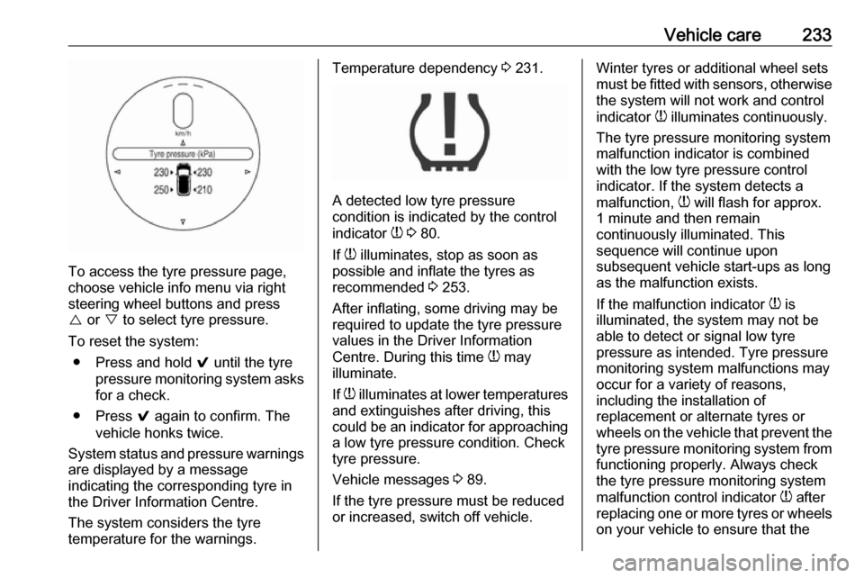
To access the tyre pressure page,
choose vehicle info menu via right
steering wheel buttons and press
{ or } to select tyre pressure.
To reset the system: ● Press and hold 9 until the tyre
pressure monitoring system asks
for a check.
● Press 9 again to confirm. The
vehicle honks twice.
System status and pressure warnings
are displayed by a message
indicating the corresponding tyre in
the Driver Information Centre.
The system considers the tyre
temperature for the warnings.
Temperature dependency 3 231.
A detected low tyre pressure
condition is indicated by the control
indicator w 3 80.
If w illuminates, stop as soon as
possible and inflate the tyres as
recommended 3 253.
After inflating, some driving may be
required to update the tyre pressure
values in the Driver Information
Centre. During this time w may
illuminate.
If w illuminates at lower temperatures
and extinguishes after driving, this
could be an indicator for approaching a low tyre pressure condition. Check
tyre pressure.
Vehicle messages 3 89.
If the tyre pressure must be reduced or increased, switch off vehicle.
Winter tyres or additional wheel sets
must be fitted with sensors, otherwise the system will not work and control
indicator w illuminates continuously.
The tyre pressure monitoring system
malfunction indicator is combined
with the low tyre pressure control
indicator. If the system detects a
malfunction, w will flash for approx.
1 minute and then remain
continuously illuminated. This
sequence will continue upon
subsequent vehicle start-ups as long
as the malfunction exists.
If the malfunction indicator w is
illuminated, the system may not be
able to detect or signal low tyre
pressure as intended. Tyre pressure
monitoring system malfunctions may
occur for a variety of reasons,
including the installation of
replacement or alternate tyres or wheels on the vehicle that prevent the
tyre pressure monitoring system from functioning properly. Always check
the tyre pressure monitoring system
malfunction control indicator w after
replacing one or more tyres or wheels
on your vehicle to ensure that the