seat adjustment OPEL ANTARA 2009 Owners Manual
[x] Cancel search | Manufacturer: OPEL, Model Year: 2009, Model line: ANTARA, Model: OPEL ANTARA 2009Pages: 234, PDF Size: 3.01 MB
Page 7 of 234

In brief7
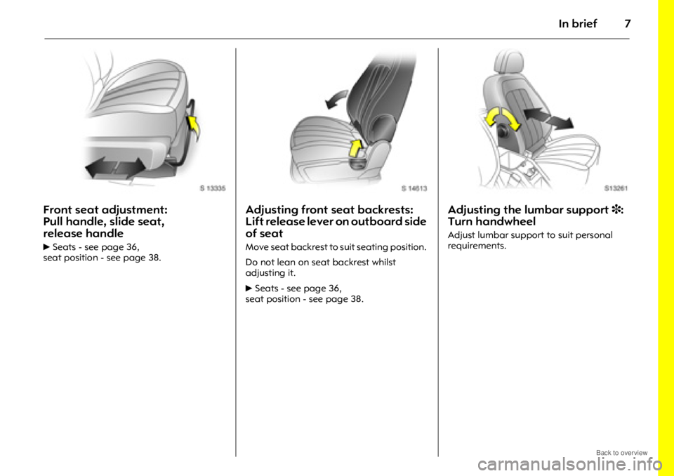
Front seat adjustment:
Pull handle, slide seat,
release handle
6Seats - see page 36,
seat position - see page 38.
Adjusting front seat backrests:
Lift release lever on outboard side
of seat
Move seat backrest to suit seating position.
Do not lean on seat backrest whilst
adjusting it.
6 Seats - see page 36,
seat position - see page 38.
Adjusting the lumbar support 3:
Turn handwheel
Adjust lumbar support to suit personal
requirements.
Page 11 of 234

In brief11
Page
1 Side air vents ................................... 104
2 Door window defroster vents ......... 104
3 Headlamp flash and main beam .... 14
turn signal lamps .............................. 14
Peripheral lighting............................. 98
cruise control 3............................... 140
4 Infotainment system
remote control buttons ................... 101
Trip computer 3.......................... 81, 88
5 Horn ................................................... 15
6 Instruments ........................................ 70
7 Windscreen and tailgate
wipers and washers .................... 15, 16
headlamp washers 3........................ 16
8 Central information display for time,
date, outside temperature,
Infotainment system,
check control 3................................. 91
Trip computer 3.......................... 81, 88 Page
9 Centre air vents ............................... 104
10 Hazard warning ................................ 14
Park pilot 3..................................... 142
Descent Control System (DCS) ....... 138
Electronic Stability Control (ESC) ... 136
Front passenger’s
seat belt reminder 3......................... 46
Fold in exterior mirrors 3................. 30
Control indicator for
anti-theft alarm system 3................ 29
11 Infotainment system ....................... 101
12 Front passenger’s airbag ................. 52
13 Glove compartment.................. 64, 105
14 Fuse box .......................................... 182
15 Climate control................................ 103
16 Ignition switch ................................... 13 Page
17 Accelerator pedal ........................... 127
18 Driver’s airbag .................................. 52
19 Brake pedal............................. 127, 146
20 Clutch pedal 3........................ 127, 128
21 Steering wheel adjustment .............. 13
22 Bonnet release ................................ 171
23 Coin storage...................................... 67
24 Card holder ....................................... 67
25 Parking lamps ................................... 94
dipped beam .............................. 14, 95
automatic dipped beam
activation 3...................................... 95
headlamp range adjustment 3....... 97
front fog lamps ................................. 96
fog tail lamp ..................................... 96
instrument illumination .................... 98
Page 12 of 234

In brief12
Control indicators
uABS (Anti-lock Brake System):
see page 148.
gTrailer indicator 3:
see page 70.
4Brake system:
see pages 70, 145.
rPark pilot 3:
see pages 71, 142.
5DCS (Descent Control System):
see pages 71, 138.
BAWD (All Wheel Drive):
see pages 71, 121.
7ESC Active & Warning
(Electronic Stability Control):
see page 136.
AESC Not Ready:
see page 136.
JESC OFF:
see page 136.
qAutomatic headlamp range
adjustment 3 :
see pages 71, 97.
WCoolant temperature:
see pages 71, 195.
oElectronic immobiliser:
see pages 22, 72.
9Door open:
see page 72.
3Engine electronics,
transmission electronics 3:
see pages 72, 134.
vAirbag systems 3,
belt tensioners:
see pages 44, 52.
1Tailgate open:
see page 72.
XDriver’s seat belt reminder:
see page 72.
OTurn signal lamps:
see pages 14, 72, 95.
YLow fuel level:
see pages 72, 76, 132, 225.
>Front fog lamps:
see pages 73, 96.
rFog tail lamp:
see pages 73, 96.
PHeadlamp main beam:
see pages 14, 73, 95.
GLow windscreen washer fluid:
see page 73.
NWater in diesel fuel filter 3:
see pages 73, 194.
CChange engine oil 3:
see page 73.
NPreheating for diesel engines 3:
see pages 19, 73.
IDPF (Diesel particle filter) 3:
see pages 73, 135.
mCruise control 3:
see page 140.
SEngine oil level 3:
see page 73.
2Power steering:
see page 73.
aAnti-theft alarm system activation
without monitoring of passenger
compartment and vehicle tilt 3:
see page 28.
IEngine oil pressure:
see page 74.
pAlternator:
see page 74.
ZExhaust emissions:
see pages 74, 134.
0Winter program:
see pages 74, 117.
Page 38 of 234

Seats, interior38
AdjustmentThe seat position can be adjusted by
means of switches on the outboard side of
the seat.
Adjusting the longitudinal position:
Move front switch forwards/backwards.
Height adjustment:
To adjust height of front part of seat
cushion, push front part of switch up/down.
To adjust height of rear part of seat
cushion, push rear part of switch up/down.
To adjust height of entire seat cushion,
push both front and re ar parts of switch
up/down. Seat backrest adjustment:
Move upper part of rear switch forwards/
backwards.
Operate switch until desired seat position is
reached. Seat position - see next column.
After adjusting the seat, adjust height of
seat belt - see page 47.
The seat backrest must not be tilted back
too far (recommended maximum tilting
angle approx. 25°).Seat position
Adjust driver’s seat such that, with the
driver sitting upright,
the steering wheel is
held in the area of its upper spokes with the
driver’s arms slightly bent.
Slide front passenger’s seat as far back as
it will go.
The seat backrests must not be tilted back
too far (recommended maximum tilting
angle approx. 25°).
9 Warning
Disregard can lead to injuries which could
be fatal. Vehicle passengers must be
informed accordingly.
Page 41 of 234

Seats, interior41
To raise the seat, lift backrest release lever
and push backrest to upright position.
Push and pull on seat backrest to ensure it
is locked, thus avoiding excessive forward
movement in the event of a collision.
Rear seats
To adjust backrests, lift release lever
located on top of backrest and move
backrest forwards or backwards to desired
position.
Do not lean on seat backrest whilst
adjusting it or make adjustments while the
vehicle is moving.
When folding the rear seat backrests,
ensure the seat belts are unbuckled. Folding rear seat backrests
The luggage compartment can be
enlarged by folding the rear seat backrests
onto the seat cushions.
To fold rear seat backrests separately,
unbuckle all three rear seat belts and
ensure front seats are not in reclined
position.
Push head restraints
all the way down, lift
backrest release lever and fold backrest
forwards and down onto seat cushion.
Do not allow passengers to sit on folded
backrest, or place an y unrestrained loads
on it.
9 Warning
If longer objects, e.g. skis, are to be
carried on the back of the front
passenger’s seat backrest, ensure they
are not in the area in which the front
passenger’s airbag inflates or in the area
between the seat backrest and the
vehicle body. In the event of a collision,
such objects may be thrown through the
vehicle.
The load must not hinder hand brake
operation or gearshifting.
Disregard of these notes can lead to
injuries which may be fatal.
Page 47 of 234

Seats, interior47
Seat belt height adjustmentof front seat belt upper anchorage points
zDo not adjust height whilst driving.
z Squeeze release buttons together and
slide adjuster up or down to desired
position.
z Ensure sliding height adjuster latches
into position.
Height adjuster can also be moved up
without squeezing release buttons. Removing the beltTo remove the belt, press the red release
button on the belt
buckle; the belt will
retract automatically.
Guide the belt as it retracts, to prevent
personal injury and damage to interior
surfaces.
Always ensure you position the release
button so that you can unbuckle the seat
belt quickly if necessary.
Child restraint systems 3
Opel child restraint systems are designed
specifically for your vehicle and thus
provide optimum safety for your child in
the event of an impact. The use of an Opel
child restraint system is therefore
recommended.
If a different child safe ty seat is used, follow
the manufacturer’s instructions for fitting
and use.
Selecting the right system
Your child should be transported facing
rearwards in the vehicle as long as
possible. The child’s neck area is still very
weak and in an accident they suffer less
stress in the semi-prone rearward position
than when sitting upright.
9 Warning
Disregard of these instructions may lead
to injuries or endanger life.
Page 97 of 234

Lighting97
Hazard warning lamps
To switch on, press button ¨.
To switch off, press button ¨ again.
To aid location of the pushbutton, the red
surface is illuminated when the ignition is
switched on. When the button is pressed,
its control indicator flashes in unison with
the hazard warning lamps.
Headlamp range adjustment q
Manual headlamp range adjustment 3
With dipped beam switched on, adjust
headlamp range to suit vehicle load.
Correct adjustment of the headlamp range
reduces dazzle for other road users.
Automatic level control system 3 -
see page 143.
Vehicles without level control system Vehicles with level control system
Automatic headlamp range
adjustment
3
On vehicles with Xenon headlamps, the
range of the headlamps is adjusted
automatically based on vehicle load.
If control indicator q for automatic
headlamp range adjustment illuminates in
the instrument panel while driving, a fault
has occurred.
Have the cause of the fault remedied
immediately. Consult a workshop.
z Front seats occupied = 0
z All seats occupied = 1
z All seats occupied and load in
luggage compartment =2
z Driver’s seat occupied and load
in luggage compartment =3
z
Front seats occupied = 0
z All seats occupied = 1
z All seats occupied and load in
luggage compartment =1
z Driver’s seat occupied and load
in luggage compartment =2
Page 105 of 234

Climate control105
Heated rear window,
heated exterior mirrors 3
Operational only in ignition switch
positions ACC or ON.
Control indicator in button.
Turn off as soon as vision is clear.
Rear window and exterior mirror heating is
switched off automatically after approx.
15 minutes.
To avoid discharging the battery, do not
operate when you are just starting the
vehicle, or if there is a build up of snow or
ice. Operate only with the engine running.
Do not use sharp instruments or abrasive
cleaners on rear window or exterior mirrors,
and avoid scratching or damaging their
heating elements.
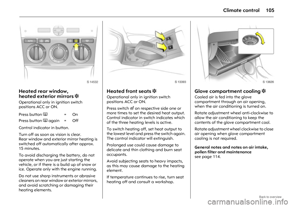
Heated front seats 3
Operational only in ignition switch
positions ACC or ON.
Press switch ß on respective side one or
more times to set the desired heat output.
Control indicator in switch indicates which
of the three heating levels is active.
To switch heating off, set heat output to
the lowest level and press the switch again.
The control indicato r will extinguish.
Prolonged use could cause damage to
delicate and thin clothing and burn seat
occupants.
Avoid subjecting seats to heavy impacts,
as this may cause damage to the heating
element.
If temperature continues to rise, turn seat
heating off and consult a workshop.
Glove compartment cooling 3
Cooled air is fed into the glove
compartment through an air opening,
when the air conditioning is turned on.
Rotate adjustment wheel anti-clockwise to
allow the air conditioning to keep the
contents of the glove compartment cool.
Rotate adjustment wheel clockwise to close
air opening when glove compartment
cooling is not required.
General notes and notes on air intake,
pollen filter and maintenance
see page 114.
Press button
Ü=On
Press button Ü again = Off
Page 143 of 234

Driving and operation143
Control indicator for park pilotControl indicator r illuminates while
driving if there is a fault in the system.
If the acoustic signal sounds 3 times
continuously when there are no obstacles
near the front or rear bumper, there is a
fault in the system.
Have the cause of the fault remedied by a
workshop. To ensure the safety of other road users
and people in the vicinity and to avoid
damage to the vehicle, remember:
z
The park pilot should only be considered
as a supplementary function. Normal
precautions should be maintained when
reversing. Check the rear view and use
the mirrors when reversing.
z Do not push, scratch or otherwise
damage the sensors.
z Do not use high-pressure jet cleaners to
clean the sensors. Clean only with a soft
sponge and clean water.
Automatic level control 3
Automatic level control makes it possible to
keep the height of the vehicle constant
when subjected to different loads in the
rear (e.g. when passengers are occupying
the rear seats or when towing a caravan/
trailer). This significantly improves driving
conditions.
The vehicle is automatically raised at the
rear to its previous unloaded level,
increasing spring travel and ground
clearance.
Headlamp range adjustment -
see page 97.
In the event of malfunctions, do not utilise
the vehicle’s full load capacity. Have the
cause of the fault remedied by a workshop
without delay.
Page 185 of 234

Self-help, vehicle care185
Bulb replacement
Before replacing a bulb , switch off ignition
and relevant switch.
Only hold new bulbs at base! Do not touch
the bulb glass with bare hands, otherwise
fingerprints on the glass evaporate and
residue builds up on the reflector
eventually resulting in a dull reflector.
Inadvertently stained bulbs may be
cleaned with a clean lint-free cloth, using
alcohol or white spirit.
Replacement bulb must be in accordance
with data on base of defective bulb. Do not
exceed wattage given on bulb base.
Headlamp aiming
We recommend that headlamp aiming be
carried out by a work shop, which will have
special equipment.
When aiming your headlamps, the manual
headlamp range adjustment 3 must be set
to 7. Headlamp removal
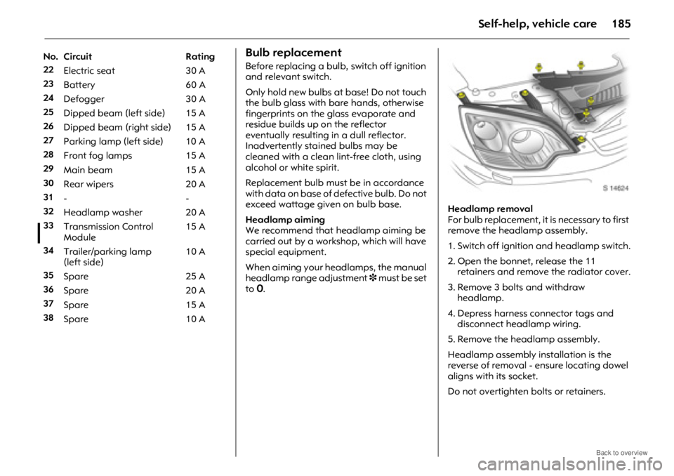
For bulb replacement, it is necessary to first
remove the headlamp assembly.
1. Switch off ignition and headlamp switch.
2. Open the bonnet, release the 11
retainers and remove the radiator cover.
3. Remove 3 bolts and withdraw headlamp.
4. Depress harness connector tags and disconnect head lamp wiring.
5. Remove the headlamp assembly.
Headlamp assembly installation is the
reverse of removal - ensure locating dowel
aligns with its socket.
Do not overtighten bolts or retainers.
No. Circuit Rating
22
Electric seat 30 A
23 Battery 60 A
24 Defogger 30 A
25 Dipped beam (left side) 15 A
26 Dipped beam (right side) 15 A
27 Parking lamp (left side) 10 A
28 Front fog lamps 15 A
29 Main beam 15 A
30 Rear wipers 20 A
31 --
32 Headlamp washer 20 A
33 Transmission Control
Module 15 A
34 Trailer/parking lamp
(left side) 10 A
35 Spare 25 A
36 Spare 20 A
37 Spare 15 A
38 Spare 10 A