sensor OPEL ASTRA J 2015 Manual user
[x] Cancel search | Manufacturer: OPEL, Model Year: 2015, Model line: ASTRA J, Model: OPEL ASTRA J 2015Pages: 343, PDF Size: 10.27 MB
Page 207 of 343

Driving and operating205
Due to the high position of the camera
the rear bumper can be seen on the
display as a guide to position.
The area displayed by the camera is
limited. The distance of the image that appears on the display differs from
the actual distance.
Guiding lines
Dynamic guiding lines are horizontal
lines in 1 metre intervals projected on
the picture to define the distance to
shown objects.Trajectory lane of the vehicle is
shown in accordance with the
steering angle.
The function can be deactivated in the
Settings menu in the Info-Display.
Vehicle personalisation 3 132.
Warning symbols
Warning symbols are indicated as
triangles 9 on the picture which show
obstacles detected by the rear
sensors of the advanced parking
assist.
Display settings
Brightness can be set with the up/
down buttons of the multifunction
knob.
Contrast can be set with left/right
buttons of the multifunction knob.
Deactivation
The camera is deactivated when a
certain forward speed is exceeded or if reverse gear is not engaged for
approx. 10 seconds.
Activation or deactivation of the rear
view camera can be changed in the Settings menu in the Info-Display.
Vehicle personalisation 3 132.
Page 253 of 343

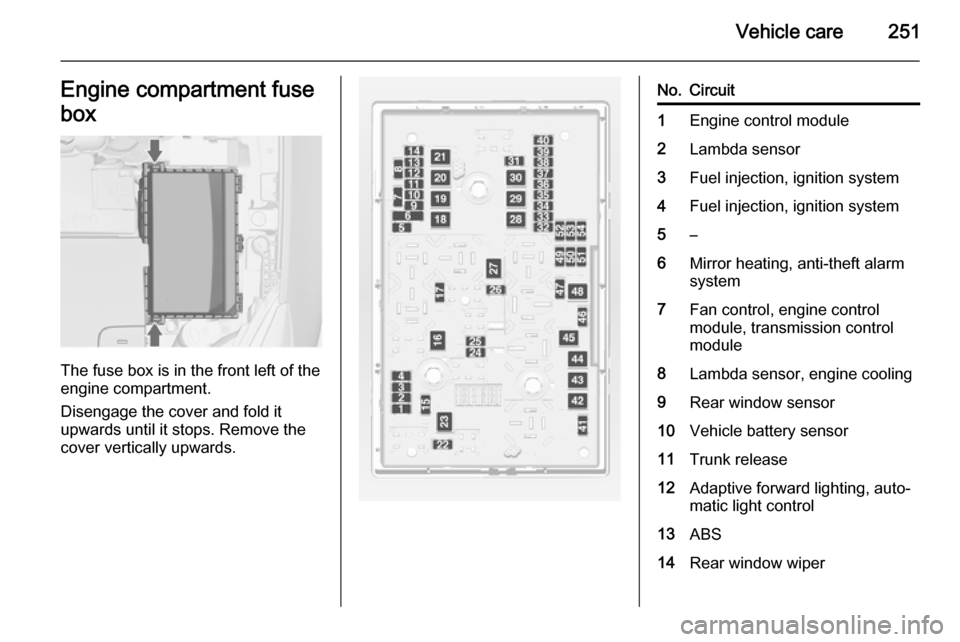
Vehicle care251Engine compartment fuse
box
The fuse box is in the front left of the
engine compartment.
Disengage the cover and fold it
upwards until it stops. Remove the
cover vertically upwards.
No.Circuit1Engine control module2Lambda sensor3Fuel injection, ignition system4Fuel injection, ignition system5–6Mirror heating, anti-theft alarm
system7Fan control, engine control
module, transmission control
module8Lambda sensor, engine cooling9Rear window sensor10Vehicle battery sensor11Trunk release12Adaptive forward lighting, auto‐
matic light control13ABS14Rear window wiper
Page 254 of 343

252Vehicle care
No.Circuit15Engine control module16Starter17Transmission control module18Heated rear window19Front power windows20Rear power windows21Rear electrical centre22Left high beam (Halogen)23Headlamp washer system24Right low beam (Xenon)25Left low beam (Xenon)26Front fog lights27Diesel fuel heating28Start stop system29Electric parking brake30ABS31Adaptive cruise controlNo.Circuit32Airbag33Adaptive forward lighting, auto‐
matic light control34Exhaust gas recirculation35Exterior mirror, rain sensor36Climate control37Canister vent solenoid38Vacuum pump39Central control module40Windscreen washer, rear
window washer system41Right high beam (Halogen)42Radiator fan43Windscreen wiper44Windscreen wiper45Radiator fan46–No.Circuit47Horn48Radiator fan49Fuel pump50Headlamp levelling, adaptive
forward lighting51Air shutter52Auxiliary heater, diesel engine53Transmission control module,
engine control module54Vacuum pump, instrument
panel cluster, heating ventila‐
tion, air conditioning system
After having changed defective fuses,
close the fuse box cover and press
until it engages.
If the fuse box cover is not closed
correctly, malfunction may occur.
Page 256 of 343

254Vehicle care
No.Circuit14Diagnostic connector15Airbag16Power outlet17Air conditioning system18Logistics19Body control module20Body control module21Instrument panel cluster, anti-
theft alarm system22Ignition sensor23Body control module24Body control module25–26Power outlet load compartment
(if no load compartment fuse
box) (Sports tourer only)Load compartment fuse
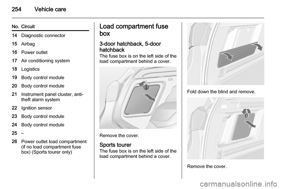
box
3-door hatchback, 5-door
hatchback
The fuse box is on the left side of the load compartment behind a cover.
Remove the cover.
Sports tourer
The fuse box is on the left side of the
load compartment behind a cover.
Fold down the blind and remove.
Remove the cover.
Page 262 of 343

260Vehicle careCaution
Tyre pressure monitoring system
warns only about low tyre pressure condition and does not replace
regular tyre maintenance by the
driver.
All wheels must be equipped with pressure sensors and the tyres must
have the prescribed pressure.
Note
In countries where the tyre pressure
monitoring system is legally
required, the use of wheels without
pressure sensors will invalidate the
vehicle type approval.
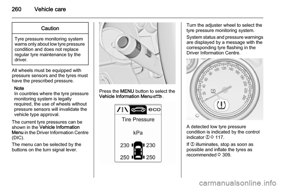
The current tyre pressures can be
shown in the Vehicle Information
Menu in the Driver Information Centre
(DIC).
The menu can be selected by the
buttons on the turn signal lever.
Press the MENU button to select the
Vehicle Information Menu X.
Turn the adjuster wheel to select the
tyre pressure monitoring system.
System status and pressure warnings
are displayed by a message with the
corresponding tyre flashing in the
Driver Information Centre.
A detected low tyre pressure
condition is indicated by the control
indicator w 3 117.
If w illuminates, stop as soon as
possible and inflate the tyres as
recommended 3 309.
Page 263 of 343

Vehicle care261
If w flashes for 60-90 seconds and
then illuminates continuously, there is
a fault in the system. Consult a
workshop.
After inflating, driving may be
required to update the tyre pressure
values in the DIC. During this time w
may illuminate.
If w illuminates at lower temperatures
and extinguishes after some driving,
this could be an indicator for getting low pressure. Check tyre pressure.
Vehicle messages 3 126.
If the tyre pressure must be reduced
or increased, switch off ignition.
Only mount wheels with pressure
sensors, otherwise the tyre pressure
will not be displayed and w
illuminates continuously.
A temporary spare wheel is not
equipped with pressure sensors. The
tyre pressure monitoring system is
not operational for these wheels.
Control indicator w illuminates. For
the further three wheels the system
remains operational.The use of commercially available
liquid tyre repair kits can impair the
function of the system. Factory-
approved repair kits can be used.
External high-power radio equipment
could disrupt the tyre pressure
monitoring system.
Each time the tyres are replaced, tyre pressure monitoring system sensors
must be dismounted and serviced.
For the screwed sensor: replace
valve core and sealing ring. For
clipped sensor: replace complete
valve stem.
Vehicle loading status
Adjust tyre pressure to load condition according to tyre information label or
tyre pressure chart 3 309, and select
the relevant setting in the menu Tire
Load in the DIC, Vehicle Information
Menu 3 119.
Select:
■ Light for comfort pressure up to
3 people
■ Eco for Eco pressure up to
3 people
■ Max for full loading
TPMS Sensor Matching
Process
Each TPMS sensor has a unique
identification code. The identification
code must be matched to a new tyre/
wheel position after rotating the tyres
or exchanging the complete wheel set and if one or more TPMS sensors
were replaced. The TPMS sensor
Page 264 of 343

262Vehicle care
matching process should also be
performed after replacing a spare tyre with a road tyre containing the TPMS
sensor.
The malfunction light and the warning
message or code should go off at the
next ignition cycle. The sensors are
matched to the tyre/wheel positions,
using a TPMS relearn tool, in the
following order: left side front tyre,
right side front tyre, right side rear tyre and left side rear tyre. The turn signal
light at the current active position is
illuminated until sensor is matched.
Consult your workshop for service or
to purchase a relearn tool. There are
two minutes to match the first tyre/
wheel position, and five minutes
overall to match all four tyre/wheel
positions. If it takes longer, the
matching process stops and must be
restarted.The TPMS sensor matching process
is:
1. Apply the parking brake; on vehicles with automatic
transmission set the selector lever
to P.
2. Turn the ignition on.
3. Use the MENU button on the turn
signal lever to select the Vehicle
Information Menu in the Driver
Information Centre (DIC).
4. Turn the adjuster wheel to scroll to
the tyre pressure menu.
5. Press the SET/CLR button to
begin the sensor matching
process. A message requesting
acceptance of the process should
display.
6. Press the SET/CLR button again
to confirm the selection. The horn sounds twice to signal the
receiver is in relearn mode.
7. Start with the left side front tyre.
8. Place the relearn tool against the tyre sidewall, near the valve stem.Then press the button to activate
the TPMS sensor. A horn chirpconfirms that the sensor
identification code has been
matched to this tyre and wheel
position.
9. Proceed to the right side front tyre,
and repeat the procedure in Step 8.
10. Proceed to the right side rear tyre,
and repeat the procedure in
Step 8.
11. Proceed to the left side rear tyre, and repeat the procedure in
Step 8. The horn sounds twice to
indicate the sensor identification
code has been matched to the left side rear tyre, and the TPMS
sensor matching process is no
longer active.
12. Turn off the ignition.
13. Set all four tyres to the recommended air pressure level
as indicated on the tyre pressure
label.
14. Ensure the tyre loading status is set according selected pressure
3 119.