steering OPEL ASTRA J 2015 Manual user
[x] Cancel search | Manufacturer: OPEL, Model Year: 2015, Model line: ASTRA J, Model: OPEL ASTRA J 2015Pages: 343, PDF Size: 10.27 MB
Page 211 of 343

Driving and operating209signs. Do not ignore traffic signs
which are not displayed by the
system.
The system does not discern any
other than the conventional traffic signs that might give or end a
speed limit.
Do not let this special feature
tempt you into taking risks when
driving.
Always adapt speed to the road
conditions.
The driver assistance systems do not relieve the driver from full
responsibility for vehicle
operation.
Lane departure warning
The lane departure warning system
observes the lane markings between
which the vehicle is driving via a front camera. The system detects lane
changes and warns the driver in the
event of an unintended lane change
via visual and acoustic signals.
Criteria for the detection of an
unintended lane change are:
■ no operation of turn signals
■ no brake pedal operation
■ no active accelerator operation or speeding-up
■ no active steering
If the driver is active, no warning will
be issued.
Activation
The lane departure warning system is activated by pressing the ) button.
The illuminated LED in the button
indicates that the system is switched
on. When the control indicator ) in
the instrument cluster illuminates
green, the system is ready to operate.
The system is only operable at
vehicle speeds above 56 km/h and if
lane markings are available.
When the system recognises an
unintended lane change, the control
indicator ) changes to yellow and
flashes. Simultaneously a chime
sound is activated.
Deactivation
The system is deactivated by
pressing ) button, the LED in the
button extinguishes.
Page 219 of 343

Driving and operating217Trailer hitch
General information
Only use towing equipment that has
been approved for your vehicle.
Entrust retrofitting of towing
equipment to a workshop. It may be
necessary to make changes that
affect the cooling system, heat
shields or other equipment.
The bulb outage detection function for trailer brake light cannot detect a
partial bulb outage, e.g. in case of 4 x
5 Watt bulbs, the function only detects
lamp outage when only a single
5 Watt lamp remains or none remain.
Fitting of towing equipment could
cover the opening of the towing eye.
If this is the case use the coupling ball bar for towing. Always keep the
coupling ball bar in the vehicle.Driving characteristics and
towing tips Before attaching a trailer, lubricate
the coupling ball. However, do not do
so if a stabiliser, which acts on the
coupling ball, is being used to reduce snaking movements.
For trailers with low driving stability
and caravan trailers with a permitted
gross vehicle weight of more than
1300 kg (Sports tourer: 1200 kg) the use of a stabiliser is strongly
recommended when driving above
80 km/h.
If the trailer starts snaking, drive more
slowly, do not attempt to correct the
steering and brake sharply if
necessary.
When driving downhill, drive in the
same gear as if driving uphill and
drive at a similar speed.
Adjust tyre pressure to the value
specified for full load 3 309.Trailer towing
Trailer loads
The permissible trailer loads are
vehicle and engine-dependent
maximum values which must not be exceeded. The actual trailer load is
the difference between the actual
gross weight of the trailer and the
actual coupling socket load with the
trailer coupled.
The permissible trailer loads are
specified in the vehicle documents. In general, they are valid for gradients
up to max. 12 %.
The permitted trailer load applies up to the specified incline and up to an
altitude of 1000 metres above sea
level. Since engine power decreases
as altitude increases due to the air
becoming thinner, therefore reducing
climbing ability, the permissible gross
train weight also decreases by 10 %
for every 1000 metres of additional
altitude. The gross train weight does
not have to be reduced when driving
on roads with slight inclines (less than
8 %, e.g. motorways).
Page 223 of 343
Driving and operating221
■The coupling ball bar must be firmly
engaged in the opening.
■ The coupling ball bar must be locked and the key removed.9 Warning
Towing a trailer is permitted only
when a coupling ball bar is fitted correctly. If the coupling ball bardoes not engage correctly, seekthe assistance of a workshop.
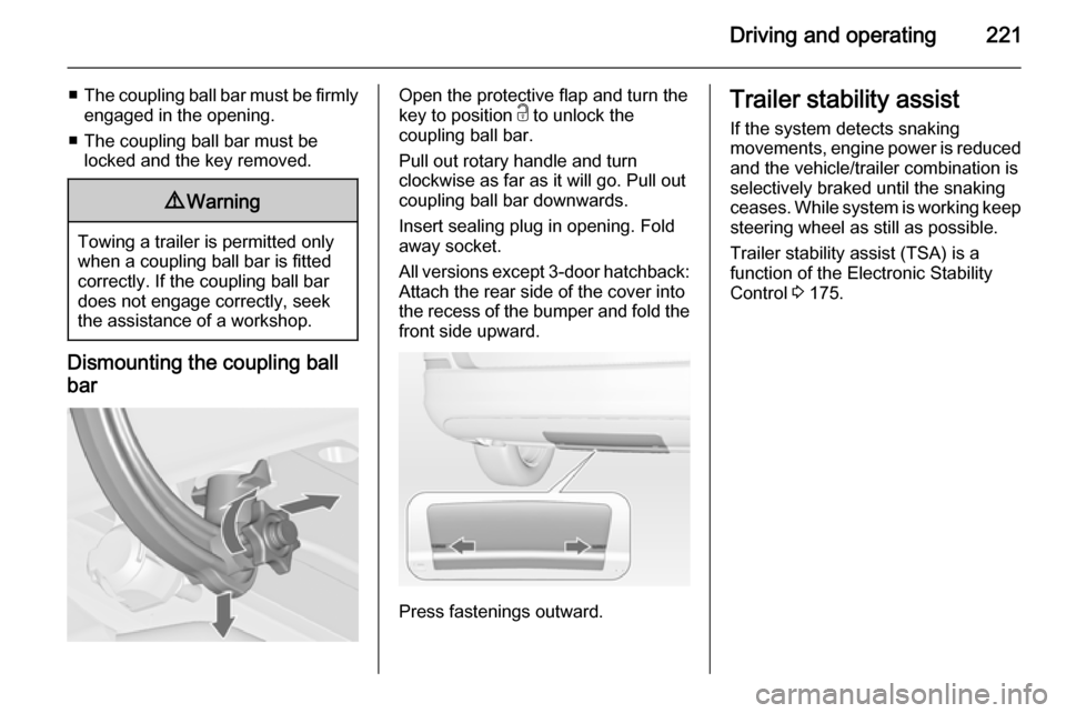
Dismounting the coupling ball
bar
Open the protective flap and turn the
key to position c to unlock the
coupling ball bar.
Pull out rotary handle and turn
clockwise as far as it will go. Pull out coupling ball bar downwards.
Insert sealing plug in opening. Fold away socket.
All versions except 3-door hatchback:
Attach the rear side of the cover into
the recess of the bumper and fold the
front side upward.
Press fastenings outward.
Trailer stability assist
If the system detects snaking
movements, engine power is reduced and the vehicle/trailer combination is
selectively braked until the snaking ceases. While system is working keep
steering wheel as still as possible.
Trailer stability assist (TSA) is a
function of the Electronic Stability
Control 3 175.
Page 228 of 343
226Vehicle care
Coolant levelCaution
Too low a coolant level can causeengine damage.
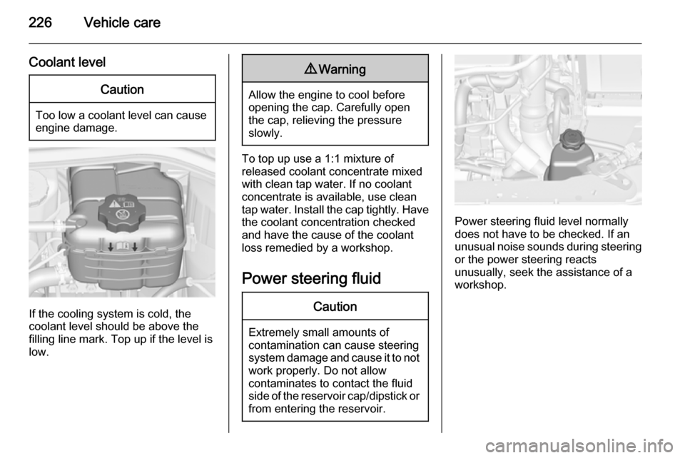
If the cooling system is cold, the
coolant level should be above the
filling line mark. Top up if the level is
low.
9 Warning
Allow the engine to cool before
opening the cap. Carefully open
the cap, relieving the pressure
slowly.
To top up use a 1:1 mixture of
released coolant concentrate mixed
with clean tap water. If no coolant
concentrate is available, use clean
tap water. Install the cap tightly. Have
the coolant concentration checked
and have the cause of the coolant
loss remedied by a workshop.
Power steering fluid
Caution
Extremely small amounts of
contamination can cause steering
system damage and cause it to not work properly. Do not allow
contaminates to contact the fluid
side of the reservoir cap/dipstick or
from entering the reservoir.
Power steering fluid level normally
does not have to be checked. If an
unusual noise sounds during steering or the power steering reacts
unusually, seek the assistance of a workshop.
Page 257 of 343
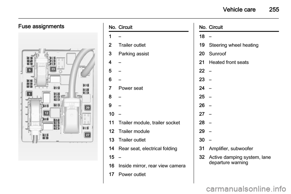
Vehicle care255
Fuse assignmentsNo.Circuit1–2Trailer outlet3Parking assist4–5–6–7Power seat8–9–10–11Trailer module, trailer socket12Trailer module13Trailer outlet14Rear seat, electrical folding15–16Inside mirror, rear view camera17Power outletNo.Circuit18–19Steering wheel heating20Sunroof21Heated front seats22–23–24–25–26–27–28–29–30–31Amplifier, subwoofer32Active damping system, lane
departure warning
Page 267 of 343
Vehicle care265
3-door hatchback
Tyre chains are permitted on tyres of
size 225/55 R 17. Always use fine
mesh chains that add no more than
10 mm to the tyre tread and the
inboard sides (including chain lock).
Tyre chains are also permitted on
tyres of size 245/45 R 18. Always use fine mesh chains that add no more
than 7 mm to the tyre tread and the
inboard sides (including chain lock).OPC Version
Tyre chains are permitted on tyres of
size 235/45 R 18. Always use fine
mesh chains that add no more than
10 mm to the tyre tread and the
inboard sides (including chain lock).General
The use of tyre chains is not permitted on the temporary spare wheel.
Tyre repair kit
Minor damage to the tyre tread can be
repaired with the tyre repair kit.
Do not remove foreign bodies from
the tyres.
Tyre damage exceeding 4 mm or that
is at tyre's sidewall cannot be repaired with the tyre repair kit.9 Warning
Do not drive faster than 80 km/h.
Do not use for a lengthy period.
Steering and handling may be
affected.
If you have a flat tyre:
Apply the parking brake and engage
first gear, reverse gear or P.
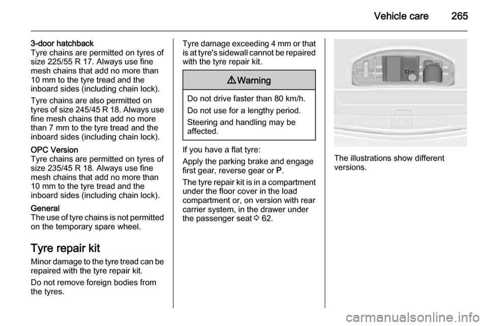
The tyre repair kit is in a compartment under the floor cover in the load
compartment or, on version with rear
carrier system, in the drawer under
the passenger seat 3 62.The illustrations show different
versions.
Page 280 of 343
278Vehicle care
2. After 5 minutes, start the otherengine. Start attempts should be
made for no longer than
15 seconds at an interval of
1 minute.
3. Allow both engines to idle for approx. 3 minutes with the leads
connected.
4. Switch on electrical consumers (e.g. headlights, heated rear
window) of the vehicle receiving
the jump start.
5. Reverse above sequence exactly when removing leads.Towing
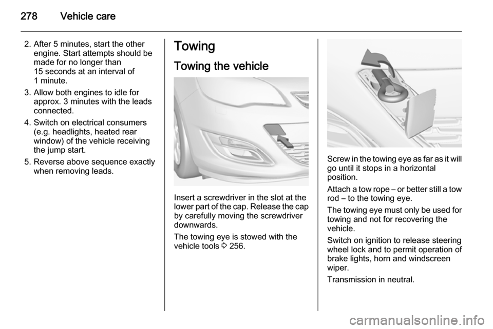
Towing the vehicle
Insert a screwdriver in the slot at the
lower part of the cap. Release the cap
by carefully moving the screwdriver
downwards.
The towing eye is stowed with the
vehicle tools 3 256.
Screw in the towing eye as far as it will
go until it stops in a horizontal
position.
Attach a tow rope – or better still a tow
rod – to the towing eye.
The towing eye must only be used for
towing and not for recovering the
vehicle.
Switch on ignition to release steering wheel lock and to permit operation of
brake lights, horn and windscreen
wiper.
Transmission in neutral.
Page 340 of 343

338
Glass panel .................................. 37
Glovebox ..................................... 60
Graphic-Info-Display, Colour- Info-Display ............................ 124
H Halogen headlights ....................231
Hand brake ......................... 171, 172
Hazard warning flashers ............144
Headlight flash ........................... 139
Headlight range adjustment ......139
Headlights................................... 137
Headlights when driving abroad 140
Head restraint adjustment .............9
Head restraints ............................ 38
Heated mirrors ............................. 32
Heated rear window ..................... 35
Heated steering wheel ...............101
Heating ........................................ 46
Heating and ventilation system . 150
Height adjustable rear floor cover 88
High beam ......................... 118, 138
High beam assist ................118, 138
Hill start assist ........................... 174
Horn ..................................... 15, 101
I
Identification plate .....................287
Ignition switch positions .............161
Immobiliser .......................... 30, 118Indicators.................................... 108
Information displays.................... 119
Instrument cluster ......................108
Instrument panel fuse box .........253
Instrument panel illumination .....249
Instrument panel illumination control .................................... 146
Instrument panel overview ........... 11
Interactive driving system ...........177
Interior care ............................... 282
Interior lighting ............................ 146
Interior lights ...................... 146, 249
Interior mirrors .............................. 32
Interruption of power supply ......170
Introduction .................................... 3
ISOFIX child restraint systems ....59
J
Jump starting ............................. 276
K Key, memorised settings ..............23
Keys ............................................. 21
Keys, locks ................................... 21
L
Lane departure warning .....116, 209
Lashing eyes ............................... 91
Lighting features .........................147
Light switch ................................ 137Load compartment ................26, 82
Load compartment cover .............86
Load compartment fuse box ......254
Loading information .....................98
Low fuel ..................................... 118
Low washer fluid ........................119
M
Malfunction indicator light ..........114
Manual anti-dazzle ......................32
Manual mode ............................. 169
Manual transmission .................. 171
Manual windows ..........................33
Memorised settings ......................23
Mirror adjustment ......................... 10
Misted light covers .....................145
N New vehicle running-in ..............161
Number plate light .....................249
O
Object detection systems ...........195
Odometer ................................... 108
Oil, engine .......................... 285, 289
Operate pedal ............................. 115
Outside temperature ..................104
Overrun cut-off ........................... 162
Page 341 of 343

339
PParking ................................ 19, 165
Parking assist ............................ 195
Parking brake ............................ 172
Parking lights ............................. 145
Particulate filter ........................... 166
Performance .............................. 295
Performing work ........................223
Pollen filter ................................. 159
Power outlets ............................. 106
Power seat adjustment ................44
Power steering............................ 116
Power steering fluid ....................226
Power windows ............................ 33
Preheating ................................. 117
Puncture ..................................... 268
Q
Quickheat ................................... 158
R Radio Frequency Identification (RFID) ..................................... 335
Radio remote control ...................22
Reading lights ............................ 147
Rear carrier system ......................64
Rear floor storage cover ..............88
Rear fog light ............................. 119
Rear fog lights ........................... 145
Rear seats .................................... 47Rear storage................................. 86
Rear view camera ...................... 204
Rear window wiper/washer ........ 104
Recommended fluids and lubricants ........................ 285, 289
Reduced engine power ..............118
Refuelling ................................... 213
Retained power off .....................161
Reversing lights .........................145
Ride control systems ..................174
Roof .............................................. 36
Roof load ...................................... 98
Roof rack ..................................... 97
S Safety belts ................................... 47
Safety net .................................... 93
Seat adjustment ....................... 7, 40 Seat belt ........................................ 9
Seat belt reminder .....................113
Seat belts ..................................... 47
Seat folding .................................. 43
Seat position ................................ 40
Selector lever ............................. 168
Service ............................... 159, 284
Service display .......................... 110
Service information ....................284
Service vehicle soon .................. 114
Side airbag system ......................51
Side blind spot alert ....................203Sidelights.................................... 137
Side turn signal lights ................247
Smartphone controller ................125
Spare wheel ............................... 272
Speed limiter............................... 181
Speedometer ............................. 108
Starting and operating ................161
Starting off ................................... 18
Starting the engine ....................161
Steering ...................................... 160
Steering wheel adjustment ..10, 100
Steering wheel controls .............100
Stop-start system........................ 163
Storage ......................................... 60
Storage compartments .................60
Sunroof ........................................ 36
Sunvisor lights ........................... 147
Sun visors .................................... 35
Symbols ......................................... 4
T Tachometer ............................... 108
Tail lights ................................... 240
Three-point seat belt .................... 48
Tools .......................................... 256
Top-tether fastening eyes ............59
Tow bar....................................... 217
Towing ................................ 217, 278
Towing another vehicle .............279
Towing equipment .....................218