tow OPEL ASTRA K 2018 Owner's Guide
[x] Cancel search | Manufacturer: OPEL, Model Year: 2018, Model line: ASTRA K, Model: OPEL ASTRA K 2018Pages: 313, PDF Size: 9.35 MB
Page 171 of 313

Driving and operating169Caution
If possible, do not interrupt
cleaning process. Drive until
cleaning is completed to avoid the need for service or repair by a
workshop.
Cleaning process not possible
If cleaning is not possible for anyreasons, control indicator Z
illuminates and a warning message
appears in the Driver Information
Centre. Engine power may be
reduced. Seek the assistance of a
workshop immediately.
Catalytic converter
The catalytic converter reduces the
amount of harmful substances in the
exhaust gases.
Caution
Fuel grades other than those listed on pages 3 217, 3 285 could
damage the catalytic converter or
electronic components.
Unburnt petrol will overheat and
damage the catalytic converter.
Therefore avoid excessive use of the starter, running the fuel tank
dry and starting the engine by
pushing or towing.
In the event of misfiring, uneven
engine running, a reduction in engine performance or other unusual
problems, have the cause of the fault
rectified by a workshop as soon as
possible. In an emergency, driving
can be continued for a short period,
keeping vehicle speed and engine
speed low.
Automatic transmission
The automatic transmission permits
automatic gearshifting (automatic
mode) or manual gearshifting
(manual mode).
Manual shifting is possible in manual mode by tapping the selector lever to
+ or - 3 171.
Transmission display
The mode or selected gear is shown
in the Driver Information Centre.
In automatic mode, the driving
programme is indicated by D.
Page 173 of 313

Driving and operating171ParkingApply the parking brake and engage
P .
The ignition key can only be removed
when the selector lever is in position
P .
Manual mode
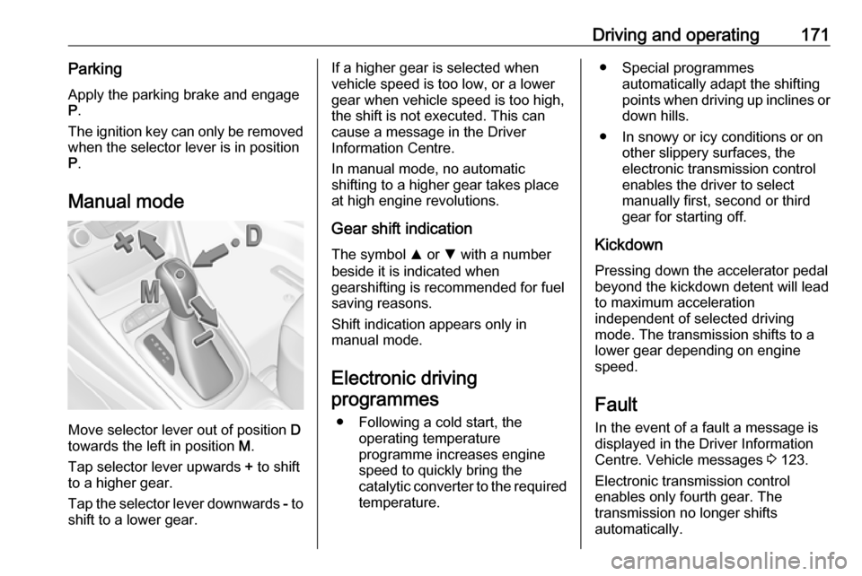
Move selector lever out of position D
towards the left in position M.
Tap selector lever upwards + to shift
to a higher gear.
Tap the selector lever downwards - to
shift to a lower gear.
If a higher gear is selected when
vehicle speed is too low, or a lower
gear when vehicle speed is too high,
the shift is not executed. This can
cause a message in the Driver
Information Centre.
In manual mode, no automatic
shifting to a higher gear takes place
at high engine revolutions.
Gear shift indication
The symbol R or S with a number
beside it is indicated when
gearshifting is recommended for fuel
saving reasons.
Shift indication appears only in
manual mode.
Electronic driving programmes
● Following a cold start, the operating temperature
programme increases engine
speed to quickly bring the
catalytic converter to the required
temperature.● Special programmes automatically adapt the shifting
points when driving up inclines or
down hills.
● In snowy or icy conditions or on other slippery surfaces, the
electronic transmission control
enables the driver to select
manually first, second or third
gear for starting off.
Kickdown Pressing down the accelerator pedal
beyond the kickdown detent will lead
to maximum acceleration
independent of selected driving
mode. The transmission shifts to a
lower gear depending on engine
speed.
Fault
In the event of a fault a message is
displayed in the Driver Information
Centre. Vehicle messages 3 123.
Electronic transmission control
enables only fourth gear. The
transmission no longer shifts
automatically.
Page 178 of 313

176Driving and operatingShift indication appears only in
manual mode.
Electronic driving programmes
● Following a cold start, the operating temperature
programme increases engine
speed to quickly bring the
catalytic converter to the required
temperature.
● The adaptive programme tailors gearshifting to the driving
conditions, e.g. greater load or
gradients.
Kickdown If the accelerator pedal is pressed
down completely in automatic mode,
the transmission shifts to a lower gear
depending on engine speed.
Fault
To prevent damage to the manual
transmission automated, the clutch is
engaged automatically at high clutch
temperatures.In the event of a fault, a warning
message is displayed in the Driver
Information Centre. Vehicle
messages 3 123.
Continued driving is restricted or not
possible, depending on the fault.
Have the cause of the fault remedied
by a workshop.Brakes
The brake system comprises two
independent brake circuits.
If a brake circuit fails, the vehicle can
still be braked using the other brake
circuit. However, braking effect is
achieved only when the brake pedal
is depressed firmly. Considerably
more force is needed for this. The
braking distance is extended. Seek the assistance of a workshop before
continuing the journey.
When the engine is not running, the
support of the brake servo unit
disappears once the brake pedal has been depressed once or twice.
Braking effect is not reduced, but
braking requires significantly greater
force. It is especially important to bear this in mind when being towed.
Control indicator R 3 111.
Antilock brake system Antilock brake system (ABS)
prevents the wheels from locking.
Page 193 of 313

Driving and operating191Switching off
Press C to switch off adaptive cruise
control. C in the Driver Information
Centre extinguishes. The stored
speed is deleted.
Switching off the ignition also
switches off adaptive cruise control
and deletes the stored speed.
Driver's attention ● Use adaptive cruise control carefully on bends or mountainroads, as it can lose the vehicle
ahead and needs time to detect it again.
● Do not use the system on slippery roads as it can create
rapid changes in tyre traction
(wheel spinning), so that you
could lose control of the vehicle.
● Do not use adaptive cruise control during rain, snow or
heavy dirt, as the radar sensor
can be covered by a water film,
dust, ice or snow. This reduces or suppresses completely thevisibility. In case of sensor
blockage, clean the sensor
cover.
System limits ● The system's automatic brake force does not permit hard
braking and the braking level
may not be sufficient to avoid a
collision.
● After a sudden lane change, the system needs a certain time to
detect the next preceding
vehicle. So if a new vehicle is
detected, the system may
accelerate instead of braking.
● Adaptive cruise control does ignore the oncoming traffic.
● Adaptive cruise control does not consider pedestrians and
animals for braking and driving off.
● Adaptive cruise control considers
stopped vehicles only at low
speed.● Do not use adaptive cruise control when towing a trailer.
● Do not use adaptive cruise control on roads with an incline ofmore than 10%.
Bends
The adaptive cruise control calculates
a predicted path based on the
centrifugal force. This predicted path
considers the current bend
characteristic, but cannot consider a
future bend change. The system may lose the current vehicle ahead or
consider a vehicle which is not in the
actual lane. This can happen when
entering or exiting a bend or if the
bend gets stronger or weaker. If it no
longer detects any vehicle ahead,
then control indicator A will
extinguish.
Page 210 of 313

208Driving and operating9Warning
Side blind spot alert does not
replace driver vision.
The system does not detect:
● vehicles outside the side blind zones which may be rapidly
approaching
● pedestrians, cyclists or animals
Before changing a lane, always
check all mirrors, look over the
shoulder and use the turn signal.
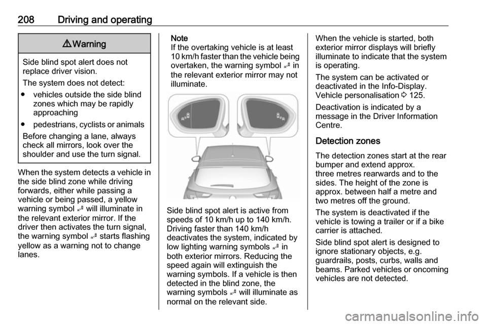
When the system detects a vehicle in the side blind zone while driving
forwards, either while passing a
vehicle or being passed, a yellow
warning symbol B will illuminate in
the relevant exterior mirror. If the
driver then activates the turn signal,
the warning symbol B starts flashing
yellow as a warning not to change
lanes.
Note
If the overtaking vehicle is at least
10 km/h faster than the vehicle being
overtaken, the warning symbol B in
the relevant exterior mirror may not
illuminate.
Side blind spot alert is active from
speeds of 10 km/h up to 140 km/h.
Driving faster than 140 km/h
deactivates the system, indicated by
low lighting warning symbols B in
both exterior mirrors. Reducing the speed again will extinguish the
warning symbols. If a vehicle is then
detected in the blind zone, the
warning symbols B will illuminate as
normal on the relevant side.
When the vehicle is started, both exterior mirror displays will briefly
illuminate to indicate that the system
is operating.
The system can be activated or
deactivated in the Info-Display.
Vehicle personalisation 3 125.
Deactivation is indicated by a
message in the Driver Information
Centre.
Detection zones
The detection zones start at the rear
bumper and extend approx.
three metres rearwards and to the
sides. The height of the zone is
approx. between half a metre and
two metres off the ground.
The system is deactivated if the
vehicle is towing a trailer or if a bike
carrier is attached.
Side blind spot alert is designed to
ignore stationary objects, e.g.
guardrails, posts, curbs, walls and
beams. Parked vehicles or oncoming
vehicles are not detected.
Page 213 of 313

Driving and operating211changed in the Settings menu in the
Info-Display. Select the relevant
setting in Settings, I Rear Camera .
Info-Display 3 121.
Vehicle personalisation 3 125.
Fault
Fault messages are displayed with a 9 on the top line of the Info-Display.
The rear view camera may not
operate properly when:
● The surrounding is dark.
● The sun or the beam of headlights is shining directly into
the camera lens.
● Ice, snow, mud, or anything else covers the camera lens. Clean
the lens, rinse it with water, and
wipe it with a soft cloth.
● The vehicle is towing a trailer.
● The vehicle had a rear end accident.
● There are extreme temperature changes.Traffic sign assistant
Functionality Traffic sign assistant detects
designated traffic signs via a front
camera and displays them in the
Driver Information Centre.
If the vehicle is equipped with an
embedded navigation system, traffic
signs from data maps may be
included additionally.
Traffic signs, which will be detected,
are:
Limit and no passing signs ● speed limit
● no passing
● end of speed limit
● end of no passingRoad signs
Beginning and end of:
● city regions (country-specific)● motorways
● A-roads
● play streetsAdd on signs ● additional hints to traffic signs
● restriction of trailer towing
● tractor constraints
● wet warning
● ice warning
● time constraints
● distance constraints
● direction arrows
Speed limit signs and no passing
signs are displayed in the Driver
Information Centre until the next
Page 219 of 313

Driving and operating2179Warning
Always keep your attention on the
road and maintain proper vehicle
position within the lane, otherwise
vehicle damage, injury or death
could occur.
Lane keep assist does not
continuously steer the vehicle.
The system may not keep the
vehicle in the lane or give an alert,
even if a lane marking is detected.
The steering of the lane keep
assist may not be sufficient to
avoid a lane departure.
The system may not detect hands-
off driving due to external
influences (road condition and
surface, weather etc). The driver
has full responsibility to control the vehicle and is always required tokeep the hands on the steeringwheel while driving.
Using the system while towing a
trailer or on slippery roads could
cause loss of control of the vehicle
and a crash. Switch the system off.
Fuel
Fuel for petrol engines Only use unleaded fuel that complies
with European standard EN 228 or equivalent.
The engine is capable of running with fuel that contains up to 10% ethanol
(e.g. named E10).
Use fuel with the recommended
octane rating. A lower octane rating
can reduce engine power and torque
and slightly increases fuel
consumption.Caution
Do not use fuel or fuel additives
that contain metallic compounds
such as manganese-based
additives. This may cause engine
damage.
Caution
Use of fuel that does not comply to EN 228 or equivalent can lead todeposits or engine damage.
Caution
Use of fuel with a lower octane
rating than the lowest possible
rating could lead to uncontrolled combustion and engine damage.
The engine-specific requirements
regarding octane rating are given in
the engine data overview 3 285. A
country-specific label at the fuel filler
flap can supersede the requirement.
Fuel additives outside Europe
Fuel should contain detergent
additives that help prevent engine
and fuel system deposits from
forming. Clean fuel injectors and
intake valves will allow the emission
control system to work properly.
Page 224 of 313

222Driving and operatingFurthermore, fuel consumption is
dependent on personal driving style as well as road and traffic conditions.Trailer hitch
General information
Only use towing equipment that has
been approved for your vehicle.
Entrust retrofitting of towing
equipment to a workshop. It may be
necessary to make changes that
affect the cooling system, heat
shields or other equipment.
The bulb outage detection function for trailer brake light cannot detect a
partial bulb outage, e.g. in case of four
times five watt bulbs, the function only detects lamp outage when only a
single five Watt lamp remains or none remain.
Fitting of towing equipment could
cover the opening of the towing eye.
If this is the case use the coupling ball
bar for towing. Always keep the
coupling ball bar in the vehicle when
not in use.Driving characteristics and
towing tips
Before attaching a trailer, lubricate
the coupling ball. However, do not do
so if a stabiliser, which acts on the coupling ball, is being used to reduce snaking movements.
During trailer towing do not exceed a
speed of 80 km/h. A maximum speed
of 100 km/h is only appropriate if an
oscillation damper is used and the
permissible gross trailer weight does
not exceed the vehicle’s curb weight.
For trailers with low driving stability
and caravan trailers, the use of an
oscillation damper is strongly
recommended.
If the trailer starts snaking, drive more
slowly, do not attempt to correct the
steering and brake sharply if
necessary.
When driving downhill, drive in the same gear as if driving uphill and
drive at a similar speed.
Adjust tyre pressure to the value
specified for full load 3 293.
Page 225 of 313

Driving and operating223Trailer towingTrailer loads
The permissible trailer loads are
vehicle and engine-dependent
maximum values which must not be
exceeded. The actual trailer load is
the difference between the actual
gross weight of the trailer and the
actual coupling socket load with the
trailer coupled.
The permissible trailer loads are
specified in the vehicle documents. In general, they are valid for gradients
up to 12%.
The permissible trailer load applies
up to the specified incline and at sea
level. Since engine power decreases
as altitude increases due to the air
becoming thinner, therefore reducing
climbing ability, the permissible gross train weight also decreases by 10%for every 1000 metres of altitude. The
gross train weight does not have to be reduced when driving on roads with
slight inclines (less than 8%, e.g.
motorways).The permissible gross train weight must not be exceeded. This weight is
specified on the identification plate
3 280.
Vertical coupling load
The vertical coupling load is the load
exerted by the trailer on the coupling
ball. It can be varied by changing the
weight distribution when loading the
trailer.
The maximum permissible vertical
coupling load (75 kg) is specified on
the towing equipment identification
plate and in the vehicle documents.
Always aim for the maximum load,
especially in the case of heavy
trailers. The vertical coupling load
should never fall below 25 kg.
Rear axle load
When the trailer is coupled and the
towing vehicle fully loaded, the
permissible rear axle load (see
identification plate or vehicle
documents) may be exceeded by 40 kg. If the permissible rear axle load is exceeded, a maximum speed of
100 km/h applies.Towing equipmentCaution
When operating without a trailer,
remove the coupling ball bar.
Stowage of coupling ball bar
The bag with the coupling ball bar is
stowed on the rear floor cover in the
load compartment.
Place the strap through the rear right
lashing eye, wrap around twice and
tighten the strap to secure the bag.
Illustration shows 5-door hatchback.
Page 226 of 313

224Driving and operating
Illustration shows Sports Tourer.Fitting the coupling ball bar
On Sports Tourer remove cover from
rear bumper by pushing.
Disengage and fold down the
connecting socket. Remove the
sealing plug from the opening for the
coupling ball bar and stow it.
Checking the tensioning of the
coupling ball bar
● Red marking on rotary knob must
point towards green marking on
coupling ball bar.
● The gap between the rotary knob
and the coupling ball bar must be approx. 6 mm.
● The key must be in position c.
Otherwise, the coupling ball bar must be tensioned before being inserted:
● Unlock coupling ball bar by turning key to position c.