light OPEL ASTRA K 2019.5 Manual user
[x] Cancel search | Manufacturer: OPEL, Model Year: 2019.5, Model line: ASTRA K, Model: OPEL ASTRA K 2019.5Pages: 311, PDF Size: 9.52 MB
Page 250 of 311
248Vehicle careNo.Circuit32DC transformer / LED display /
Electrical heater / Climate
control / Glow plug controller33Anti theft warning horn34Horn35Power outlet load compartment36Right high beam (Halogen) /
Right low beam (LED)37Left high beam (Halogen)38LED headlight / Automatic
headlight range adjustment39Front fog light40Central Gateway Module41Water in fuel sensor / Water
pump42Manual headlight range adjust‐
ment43Fuel pump44Rear view camera / Inside rear
view mirror / Trailer moduleNo.Circuit45LED headlight left / Automatic
headlight range adjustment left46Instrument cluster47Steering column lock48Rear wiper49Outside rearview mirror50LED headlight right / Automatic
headlight range adjustment
right51Left low beam (LED)52Engine control module / Trans‐
mission control module53Diesel exhaust system54Windscreen wiper55Electrical rear seat folding56–57–
After having changed defective fuses,
close the fuse box cover and press
until it engages.
If the fuse box cover is not closed
correctly, malfunction may occur.
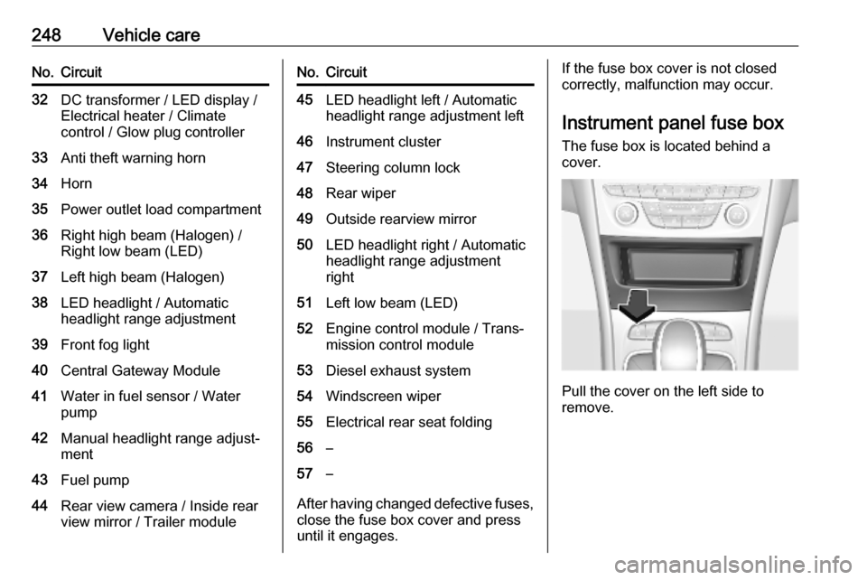
Instrument panel fuse boxThe fuse box is located behind a
cover.
Pull the cover on the left side to
remove.
Page 251 of 311
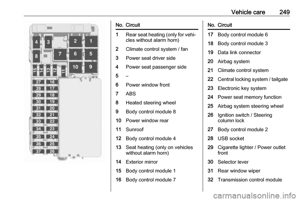
Vehicle care249No.Circuit1Rear seat heating (only for vehi‐cles without alarm horn)2Climate control system / fan3Power seat driver side4Power seat passenger side5–6Power window front7ABS8Heated steering wheel9Body control module 810Power window rear11Sunroof12Body control module 413Seat heating (only on vehicles
without alarm horn)14Exterior mirror15Body control module 116Body control module 7No.Circuit17Body control module 618Body control module 319Data link connector20Airbag system21Climate control system22Central locking system / tailgate23Electronic key system24Power seat memory function25Airbag system steering wheel26Ignition switch / Steering
column lock27Body control module 228USB socket29Cigarette lighter / Power outlet
front30Selector lever31Rear window wiper32Transmission control module
Page 259 of 311
Vehicle care257The use of commercially-available
liquid tyre repair kits can impair the
function of the system. Factory-
approved repair kits can be used.
Operating electronic devices or being
close to facilities using similar wave
frequencies could disrupt the tyre
pressure monitoring system.
Each time the tyres are replaced, tyre pressure monitoring system sensors
must be dismounted and serviced.
For the screwed sensor, replace
valve core and sealing ring. For the
clipped sensor, replace complete
valve stem.
Use only original plastic valve caps to
protect valve on any damage.Caution
Do not use metal valve caps as
they lead to valve oxidation and
damage.
Vehicle loading status
Adjust tyre pressure to load condition
according to the tyre information label or tyre pressure chart 3 290, and
select the appropriate setting in Tyre
Load within the Vehicle Information
Menu 3 114. This setting determines
the reference pressures for the tyre
pressure warnings.
The Tyre Load menu only appears
when the vehicle is at a standstill and the parking brake is applied. On
vehicles with automatic transmission
the selector lever must be in P.
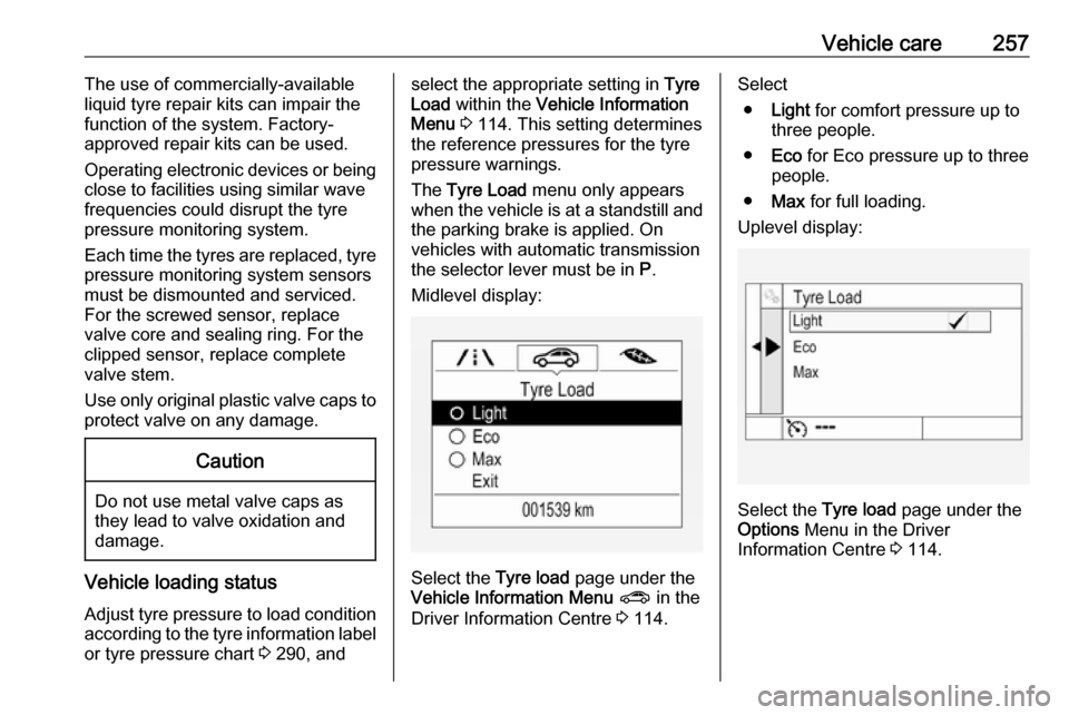
Midlevel display:
Select the Tyre load page under the
Vehicle Information Menu ? in the
Driver Information Centre 3 114.
Select
● Light for comfort pressure up to
three people.
● Eco for Eco pressure up to three
people.
● Max for full loading.
Uplevel display:
Select the Tyre load page under the
Options Menu in the Driver
Information Centre 3 114.
Page 260 of 311
258Vehicle careSelect● Light for comfort pressure up to
three people.
● Eco for Eco pressure up to
three people.
● Max for full loading.
Tyre pressure sensor matching
process
Each tyre pressure sensor has a
unique identification code. The
identification code must be matched
to a new wheel position after rotating the wheels or exchanging the
complete wheel set and if one or more tyre pressure sensors were replaced.The tyre pressure sensor matching
process should also be performed
after replacing a spare wheel with a
road wheel containing the tyre
pressure sensor.
The malfunction light w and the
warning message or code should go
off at the next ignition cycle. The
sensors are matched to the wheel
positions, using a relearn tool, in the
following order: left side front wheel,
right side front wheel, right side rearwheel and left side rear wheel. The
turn light at the current active position
is illuminated until sensor is matched.
Consult a workshop for service. There
are two minutes to match the first
wheel position, and five minutes
overall to match all four wheel
positions. If it takes longer, the
matching process stops and must be
restarted.
The tyre pressure sensor matching
process is:
1. Apply the parking brake.
2. Turn the ignition on.
3. On vehicles with automatic transmission: set the selector
lever to P.
On vehicles with manual
transmission: select neutral.
4. Midlevel display: Use MENU on the indicator lever
to select the Vehicle Information
Menu ? in the Driver
Information Centre.
Uplevel display:
Press p on the steering wheel to
open main menu page.Select the Info page with Q or P.
Confirm with 9.
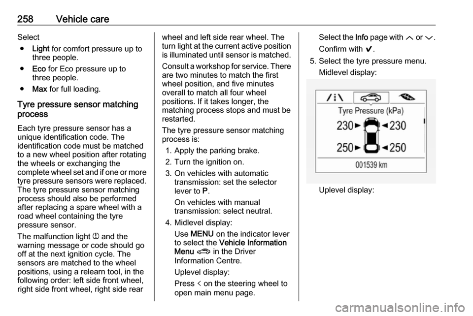
5. Select the tyre pressure menu. Midlevel display:
Uplevel display:
Page 264 of 311
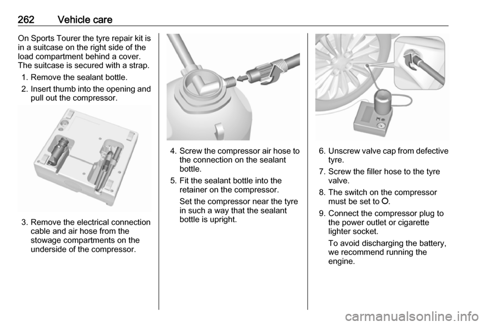
262Vehicle careOn Sports Tourer the tyre repair kit isin a suitcase on the right side of the
load compartment behind a cover.
The suitcase is secured with a strap.
1. Remove the sealant bottle.
2. Insert thumb into the opening and
pull out the compressor.
3. Remove the electrical connection cable and air hose from the
stowage compartments on the
underside of the compressor.
4. Screw the compressor air hose to
the connection on the sealant
bottle.
5. Fit the sealant bottle into the retainer on the compressor.
Set the compressor near the tyre
in such a way that the sealant
bottle is upright.6. Unscrew valve cap from defective
tyre.
7. Screw the filler hose to the tyre valve.
8. The switch on the compressor must be set to J.
9. Connect the compressor plug to the power outlet or cigarette
lighter socket.
To avoid discharging the battery, we recommend running the
engine.
Page 273 of 311
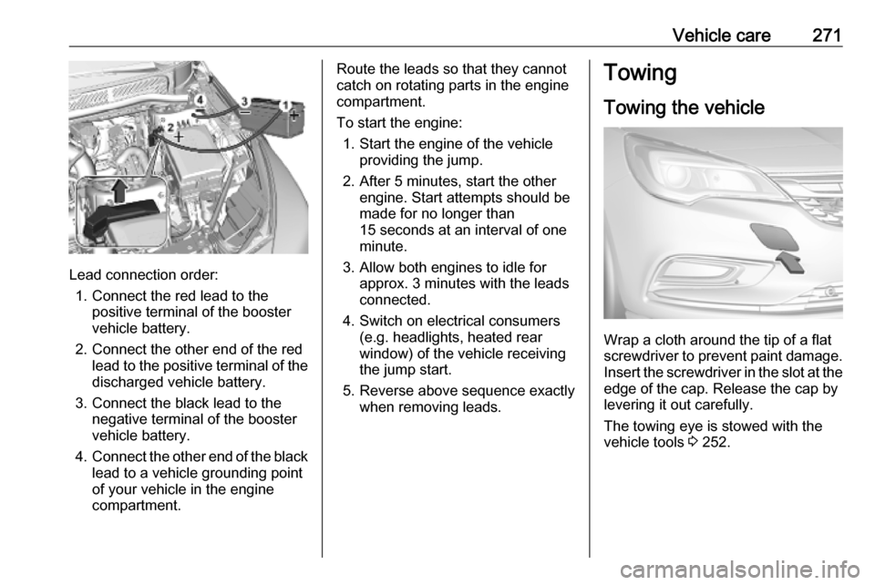
Vehicle care271
Lead connection order:1. Connect the red lead to the positive terminal of the booster
vehicle battery.
2. Connect the other end of the red lead to the positive terminal of the
discharged vehicle battery.
3. Connect the black lead to the negative terminal of the booster
vehicle battery.
4. Connect the other end of the black
lead to a vehicle grounding point
of your vehicle in the engine
compartment.
Route the leads so that they cannot
catch on rotating parts in the engine
compartment.
To start the engine: 1. Start the engine of the vehicle providing the jump.
2. After 5 minutes, start the other engine. Start attempts should be
made for no longer than
15 seconds at an interval of one
minute.
3. Allow both engines to idle for approx. 3 minutes with the leads
connected.
4. Switch on electrical consumers (e.g. headlights, heated rear
window) of the vehicle receiving
the jump start.
5. Reverse above sequence exactly when removing leads.Towing
Towing the vehicle
Wrap a cloth around the tip of a flat
screwdriver to prevent paint damage.
Insert the screwdriver in the slot at the
edge of the cap. Release the cap by
levering it out carefully.
The towing eye is stowed with the
vehicle tools 3 252.
Page 274 of 311
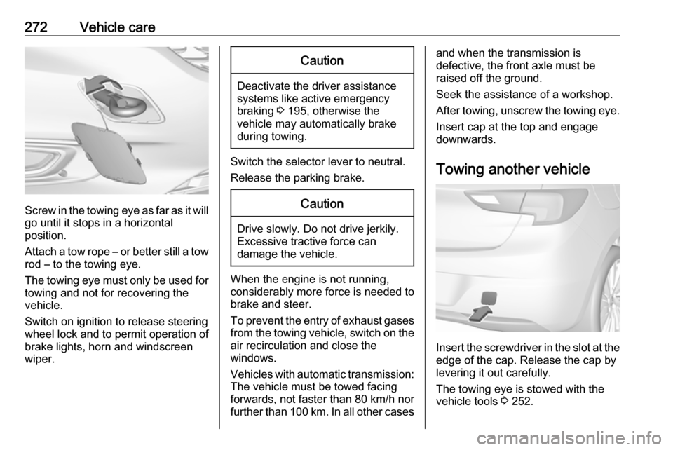
272Vehicle care
Screw in the towing eye as far as it will
go until it stops in a horizontal
position.
Attach a tow rope – or better still a tow
rod – to the towing eye.
The towing eye must only be used for towing and not for recovering the
vehicle.
Switch on ignition to release steering
wheel lock and to permit operation of
brake lights, horn and windscreen
wiper.
Caution
Deactivate the driver assistance
systems like active emergency
braking 3 195, otherwise the
vehicle may automatically brake during towing.
Switch the selector lever to neutral.
Release the parking brake.
Caution
Drive slowly. Do not drive jerkily.
Excessive tractive force can
damage the vehicle.
When the engine is not running,
considerably more force is needed to
brake and steer.
To prevent the entry of exhaust gases from the towing vehicle, switch on the
air recirculation and close the
windows.
Vehicles with automatic transmission: The vehicle must be towed facing
forwards, not faster than 80 km/h nor further than 100 km. In all other cases
and when the transmission is
defective, the front axle must be
raised off the ground.
Seek the assistance of a workshop.
After towing, unscrew the towing eye.
Insert cap at the top and engage
downwards.
Towing another vehicle
Insert the screwdriver in the slot at the edge of the cap. Release the cap by
levering it out carefully.
The towing eye is stowed with the
vehicle tools 3 252.
Page 276 of 311

274Vehicle careIf using a vehicle wash, comply with
the vehicle wash manufacturer's
instructions. The windscreen wiper and rear window wiper must be
switched off. Remove antenna and
external accessories such as roof
racks etc.
If you wash your vehicle by hand,
make sure that the insides of the
wheel housings are also thoroughly
rinsed out.
Clean edges and folds on opened
doors and the bonnet as well as the
areas they cover.
Clean bright metal mouldings with a
cleaning solution approved for
aluminium to avoid damages.Caution
Always use a cleaning agent with
a pH value of four to nine.
Do not use cleaning agents on hot surfaces.
Do not clean the engine compartmentwith a steam-jet or high-pressure jet
cleaner.
Thoroughly rinse and leather-off the vehicle. Rinse leather frequently. Use
separate leathers for painted and
glass surfaces: remnants of wax on
the windows will impair vision.
Have the door hinges of all doors
greased by a workshop.
Do not use hard objects to remove
spots of tar. Use tar removal spray on
painted surfaces.
Exterior lights
Headlight and other light covers are
made of plastic. Do not use any
abrasive or caustic agents, do not use an ice scraper, and do not clean them
dry.
Polishing and waxing
Wax the vehicle regularly (at the
latest when water no longer beads).
Otherwise, the paintwork will dry out.
Polishing is necessary only if the paint
has become dull or if solid deposits
have become attached to it.
Paintwork polish with silicone forms a
protective film, making waxing
unnecessary.Plastic body parts must not be treated with wax or polishing agents.
Windows and windscreen wiper
blades
Switch off wipers before handling in
their areas.
Use a soft lint-free cloth or chamois leather together with window cleaner
and insect remover.
When cleaning the rear window from
inside, always wipe in parallel to the
heating element to prevent damage.
For mechanical removal of ice, use a
sharp-edged ice scraper. Press the
scraper firmly against the glass so
that no dirt can get under it and
scratch the glass.
Clean smearing wiper blades with a
soft cloth and window cleaner.
Remove dirt residues from smearing
wiper blades by using a soft cloth and window cleaner. Also make sure to
remove any residues such as wax,
insect residues and similar from the
window.
Page 277 of 311

Vehicle care275Ice residues, pollution and continuous
wiping on dry windows will damage or
even destroy the wiper blades.
Sunroof Never clean with solvents or abrasive
agents, fuels, aggressive media
(e.g. paint cleaner, acetone-
containing solutions etc.), acidic or
highly alkaline media or abrasive
pads. Do not apply wax or polishing
agents to the sunroof.
Wheels and tyres
Do not use high-pressure jet
cleaners.
Clean rims with a pH-neutral wheel
cleaner.
Rims are painted and can be treated
with the same agents as the body.
Paintwork damageRectify minor paintwork damage with
a touch-up pen before rust forms.
Have more extensive damage or rust
areas repaired by a workshop.Underbody
Some areas of the vehicle underbody
have a PVC undercoating while other
critical areas have a durable
protective wax coating.
After the underbody is washed, check
the underbody and have it waxed if
necessary.
Bitumen / rubber materials could
damage the PVC coating. Have
underbody work carried out by a
workshop.
Before and after winter, wash the
underbody and have the protective
wax coating checked.
Towing equipment Do not clean the coupling ball bar with
a steam-jet or high-pressure jet
cleaner.
Air shutter
Clean the shutter system in the front
bumper to maintain correct
functionality.Interior care
Interior and upholstery
Only clean the vehicle interior,
including the instrument panel fascia
and panelling, with a dry cloth or
interior cleaner.
Clean the leather upholstery with
clear water and a soft cloth. In case of heavy soiling, use leather care.
The instrument cluster and the
displays should only be cleaned using
a soft damp cloth. If necessary use a
weak soap solution.
Clean fabric upholstery with a
vacuum cleaner and brush. Remove
stains with an upholstery cleaner.
Clothing fabrics may not be
colourfast. This could cause visible
discolourations, especially on light- coloured upholstery. Removable
stains and discolourations should be
cleaned as soon as possible.
Clean seat belts with lukewarm water or interior cleaner.
Page 303 of 311

Customer information301Operating data in the vehicleControl units process data for
operation of the vehicle.
This data includes, e.g.: ● vehicle status information (e.g. wheel rotation rate, speed,
movement delay, lateral
acceleration, "seatbelts
fastened" display),
● ambient conditions (e.g. temperature, rain sensor,
distance sensor).
As a rule such data is transient, not
stored for longer than an operational
cycle, and only processed on board
the vehicle itself. Control units often
include data storage (including the
vehicle key). This is used to allow information to be documented
temporarily or permanently on vehicle
condition, component stress,
maintenance requirements and
technical events and errors.Depending on the technical
equipment level, the data stored is as follows:
● system component operating states (e.g. fill level, tyre
pressure, battery status)
● faults and defects in important system components (e.g. lights,
brakes)
● system reactions in special driving situations (e.g. triggering
of an airbag, actuation of the
stability control systems)
● information on events damaging the vehicle
● for electric vehicles the amount of
charge in the high-voltage
battery, estimated range
In special cases (e.g. if the vehicle
has detected a malfunction), it may be
necessary to save data that would
otherwise just be volatile.
When you use services (e.g. repairs,
maintenance), the operating data
saved can be read together with the
vehicle identification number and
used when necessary. Staff working
for the service net-work ( e.g. garages,manufacturers) or third parties (e.g.
breakdown services) can read the
data from the vehicle. The same
applies to warranty work and quality
assurance measures.
Data is generally read via the OBD
(On-Board Diagnostics) port
prescribed by law in the vehicle. The operating data which is read out,
documents the technical condition of
the vehicle or individual components
and assists with fault diagnosis,
compliance with warranty obligations
and quality improvement. This data,
in particular information on
component stress, technical events,
operator errors and other faults, is
transmitted to the manufacturer
where appropriate, together with the
vehicle identification number. The
manufacturer is also subject to
product liability. The manufacturer
potentially also uses operating data
from vehicles for product recalls. This
data can also be used to check
customer warranty and guarantee
claims.