ESP OPEL ASTRA K 2020 Manual user
[x] Cancel search | Manufacturer: OPEL, Model Year: 2020, Model line: ASTRA K, Model: OPEL ASTRA K 2020Pages: 305, PDF Size: 27.84 MB
Page 214 of 305
212Driving and operatingManual switch off the lane keep assist
if the system is disturbed by tar
marks, shadows, road cracks,
temporary or construction lane
markings, or other road
imperfections.9 Warning
Always keep your attention on the
road and maintain proper vehicle
position within the lane, otherwise
vehicle damage, injury or death
could occur.
Lane keep assist does not
continuously steer the vehicle.
The system may not keep the
vehicle in the lane or give an alert,
even if a lane marking is detected.
The steering of the lane keep
assist may not be sufficient to
avoid a lane departure.
The system may not detect hands-
off driving due to external
influences like road condition and
surface and weather. The driver has full responsibility to control the
vehicle and is always required to
keep the hands on the steering
wheel while driving.
Using the system while towing a
trailer or on slippery roads could
cause loss of control of the vehicle
and a crash. Switch the system off.Fuel
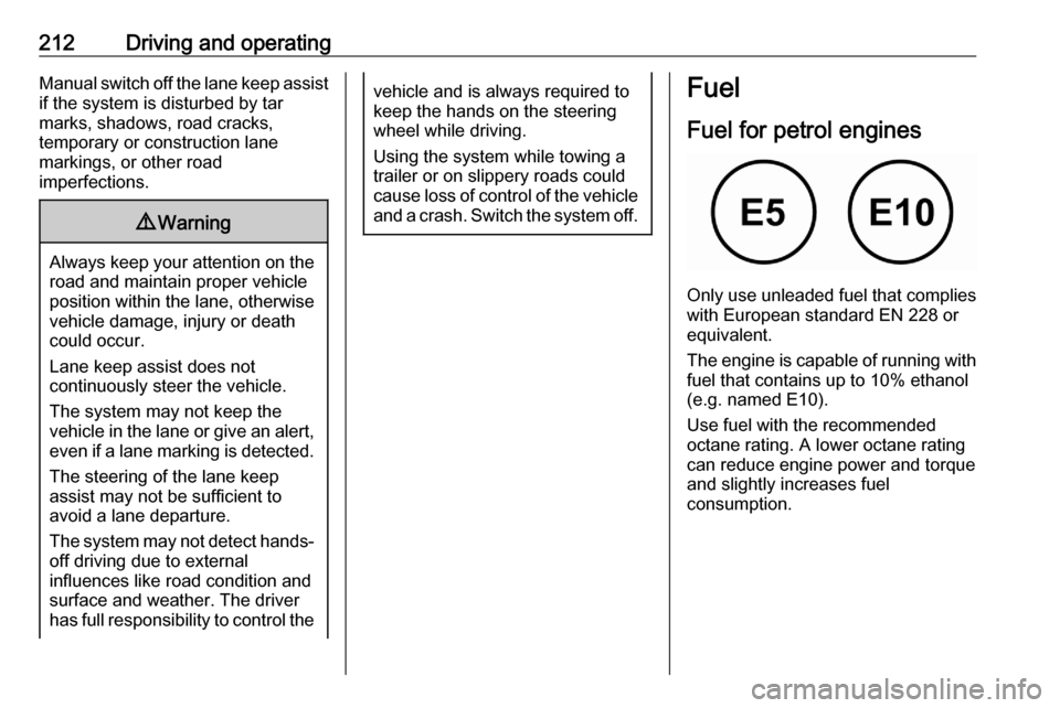
Fuel for petrol engines
Only use unleaded fuel that complies
with European standard EN 228 or
equivalent.
The engine is capable of running with
fuel that contains up to 10% ethanol
(e.g. named E10).
Use fuel with the recommended
octane rating. A lower octane rating can reduce engine power and torque
and slightly increases fuel
consumption.
Page 219 of 305

Driving and operating217Driving characteristics and
towing tips
Before attaching a trailer, lubricate
the coupling ball. However, do not do
so if a stabiliser, which acts on the
coupling ball, is being used to reduce snaking movements.
During trailer towing do not exceed a
speed of 80 km/h. A maximum speed
of 100 km/h is only appropriate if an
oscillation damper is used and the
permissible gross trailer weight does
not exceed the vehicle’s curb weight.
For trailers with low driving stability
and caravan trailers, the use of an
oscillation damper is strongly
recommended.
If the trailer starts snaking, drive more slowly, do not attempt to correct the
steering and brake sharply if
necessary.
When driving downhill, drive in the
same gear as if driving uphill and
drive at a similar speed.
Adjust tyre pressure to the value
specified for full load 3 285.Trailer towing
Trailer loads The permissible trailer loads are
vehicle and engine-dependent
maximum values which must not be
exceeded. The actual trailer load is the difference between the actual
gross weight of the trailer and the
actual coupling socket load with the
trailer coupled.
The permissible trailer loads are
specified in the vehicle documents. In general, they are valid for gradients
up to 12%.
The permissible trailer load applies
up to the specified incline and at sea
level. Since engine power decreases
as altitude increases due to the air
becoming thinner, therefore reducing
climbing ability, the permissible gross
train weight also decreases by 10%
for every 1000 m of altitude. The
gross train weight does not have to be reduced when driving on roads with
slight inclines (less than 8%, e.g.
motorways).The permissible gross train weight
must not be exceeded. This weight is
specified on the identification plate
3 276.
Vertical coupling load
The vertical coupling load is the load
exerted by the trailer on the coupling
ball. It can be varied by changing the
weight distribution when loading the
trailer.
The maximum permissible vertical
coupling load is specified on the
towing equipment identification plate
and in the vehicle documents. Always aim for the maximum load, especially in the case of heavy trailers. The
vertical coupling load should never
fall below 25 kg.
Rear axle load When the trailer is coupled and the
towing vehicle fully loaded, the
permissible rear axle load (see
identification plate or vehicle
documents) may be exceeded by 40 kg. If the permissible rear axle load
is exceeded, a maximum speed of
100 km/h applies.
Page 235 of 305

Vehicle care233
2. Disengage the plug connector bypressing the retaining lug.
3. Remove and replace the bulb unit
and attach the plug connector.
Note that the bulb and the socket
are one unit and have to be
changed together.
4. Insert the bulb socket into the light
assembly by turning clockwise
and engage.
5. Mount the light assembly by tightening the screws.
6. Attach the faceplate and tighten the screw.
Tail lights
5-door Hatchback
1. Release the cover on the respective side and remove it.
2. Vehicles with tyre repair kit: To replace bulbs on the right side,
first unscrew the plastic nut and
take out the insert with the sealant
bottle.
3. Unscrew the plastic securing nut from the inside by hand.
Page 238 of 305

236Vehicle careOn version with LED tail lights, theposition of the retaining lugs is
slightly different.
6. Remove and replace the bulb:
Tail light ( 1)
Rear fog light ( 2) (left side)
Reverse light ( 2) (right side)
On version with LED tail lights
only reverse light bulb ( 1) can be
removed and replaced.
7. Insert the bulb carrier into the tail light assembly. Attach plug to the
light assembly. Fit light assembly
on the tailgate and tighten the
screw from the inside. Attach
cover.
Depending on the version, tail lights are designed as LEDs. In case of failure, have LEDs replaced by aworkshop.
Sports Tourer
1. Release and open the cover on the respective side.
Page 243 of 305
Vehicle care241Electrical system
Fuses Data on the replacement fuse must
match the data on the defective fuse.
There are three fuse boxes in the
vehicle:
● engine compartment
● instrument panel
● load compartment
Before replacing a fuse, turn off the
respective switch and the ignition.
A blown fuse can be recognized by its melted wire.Caution
Do not replace the fuse until the
cause of the fault has been
remedied.
Some functions are protected by
several fuses.
Fuses may also be inserted without
existence of a function.
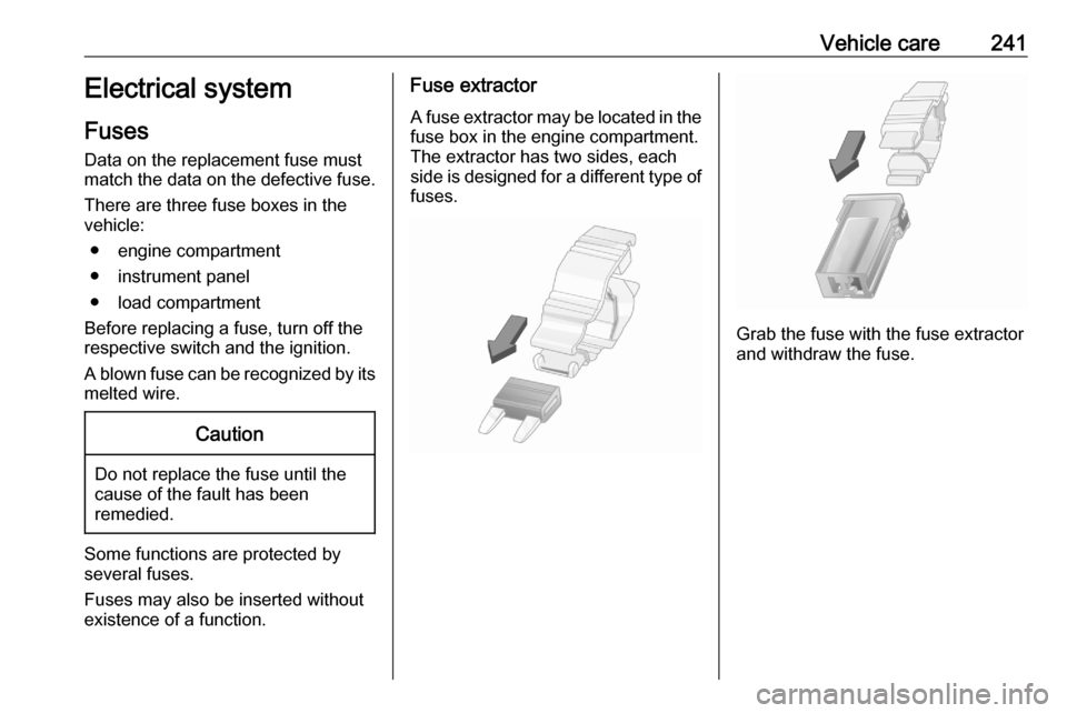
Fuse extractor
A fuse extractor may be located in the
fuse box in the engine compartment.
The extractor has two sides, each
side is designed for a different type of fuses.
Grab the fuse with the fuse extractor
and withdraw the fuse.
Page 250 of 305
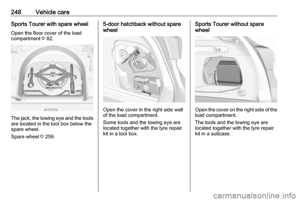
248Vehicle careSports Tourer with spare wheel
Open the floor cover of the load
compartment 3 82.
The jack, the towing eye and the tools
are located in the tool box below the
spare wheel.
Spare wheel 3 259.
5-door hatchback without spare
wheel
Open the cover in the right side wall
of the load compartment.
Some tools and the towing eye are
located together with the tyre repair
kit in a tool box.
Sports Tourer without spare
wheel
Open the cover on the right side of the load compartment.
The tools and the towing eye are
located together with the tyre repair
kit in a suitcase.
Page 252 of 305
250Vehicle careThe tyre pressure information labelon the left door frame indicates the
original equipment tyres and the
correspondent tyre pressures.
The tyre pressure data refers to cold
tyres. It applies to summer and winter tyres.
Always inflate the spare tyre to the
pressure specified for full load.
The ECO tyre pressure serves to
achieve the smallest amount of fuel
consumption possible.
Make sure tyre loading setting
matches the current tyre pressure.
Tyre loading 3 251.
Incorrect tyre pressures will impair
safety, vehicle handling, comfort and fuel economy and will increase tyre
wear.
Tyre pressures differ depending on
various options.
For the correct tyre pressure value,
follow the procedure below:
● Identify the engine identifier code.Engine data 3 280.
● Identify the respective tyre. ● The tyre pressure tables show all
possible tyre combinations
3 285.
For the tyres approved for your
vehicle, refer to the EEC Certificate of Conformity provided with your vehicle
or other national registration
documents.
The driver is responsible for correct
adjustment of tyre pressure.9 Warning
If the pressure is too low, this can
result in considerable tyre warm-
up and internal damage, leading to tread separation and even to tyre
blow-out at high speeds.
9 Warning
For specific tyres the
recommended tyre pressure as
shown in the tyre pressure table may exceed the maximum tyre
pressure as indicated on the tyre.
Never exceed the maximum tyre
pressure as indicated on the tyre.
If the tyre pressure must be reduced
or increased on a vehicle with tyre
pressure monitoring system, switch
off ignition.
Temperature dependency
The tyre pressure depends on the
temperature of the tyre. During
driving, tyre temperature and
pressure increase. Tyre pressure
values provided on the tyre
information label and tyre pressure
chart are valid for cold tyres, which means at 20 °C.
The pressure increases by nearly
10 kPa for a 10 °C temperature
increase. This must be considered
when warm tyres are checked.
The tyre pressure value displayed in
the Driver Information Centre shows
the real tyre pressure. A cooled down tyre will show a decreased value,which does not indicate an air leak.
Page 253 of 305
Vehicle care251Tyre pressure monitoringsystem
The tyre pressure monitoring system checks the pressure of all four tyres
once a minute when vehicle speed
exceeds a certain limit.Caution
Tyre pressure monitoring system
warns only about low tyre pressure condition and does not replace
regular tyre maintenance by the
driver.
All wheels must be equipped with pressure sensors and the tyres must
have the prescribed pressure.
Note
In countries where the tyre pressure
monitoring system is legally
required, the use of wheels without
pressure sensors will invalidate the
vehicle operating permit.
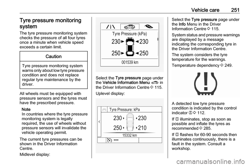
The current tyre pressures can be
shown in the Driver Information
Centre.
Midlevel display:
Select the Tyre pressure page under
the Vehicle Information Menu ? in
the Driver Information Centre 3 115.
Uplevel display:
Select the Tyre pressure page under
the Info Menu in the Driver
Information Centre 3 115.
System status and pressure warnings
are displayed by a message
indicating the corresponding tyre in
the Driver Information Centre.
The system considers the tyre
temperature for the warnings.
Temperature dependency 3 249.
A detected low tyre pressure
condition is indicated by the control
indicator w 3 112.
If w illuminates, stop as soon as
possible and inflate the tyres as
recommended 3 285.
If w flashes for 60-90 seconds then
illuminates continuously, there is a
fault in the system. Consult a
workshop.
Page 256 of 305

254Vehicle care
The legally permissible minimum
tread depth (1.6 mm) has been
reached when the tread has worn
down as far as one of the tread wear
indicators (TWI). Their position is
indicated by markings on the
sidewall.
If there is more wear at the front than
the rear, swap round front wheels and rear wheels periodically. Ensure that
the direction of rotation of the wheels
remains the same.
Tyres age, even if they are not used.
We recommend tyre replacement
every 6 years.
Changing tyre and wheel
size
If tyres of a different size than those
fitted at the factory are used, it may be necessary to reprogramme the
nominal tyre pressure and make
other vehicle modifications.
After converting to a different tyre
size, have the label with tyre
pressures replaced and the tyre
pressure monitoring system
reinitialised 3 251.9 Warning
The use of unsuitable tyres or
wheels may lead to accidents and will invalidate the vehicle
operating permit.
Wheel covers
Wheel covers and tyres that are
factory approved for the respective
vehicle and comply with all of the
relevant wheel and tyre combination
requirements must be used.
If the wheel covers and tyres used are
not factory approved, the tyres must
not have a rim protection ridge.
Wheel covers must not impair brake
cooling.9 Warning
Use of unsuitable tyres or wheel
covers could lead to sudden
pressure loss and thereby
accidents.
Vehicles with steel wheels: When
using locking wheel nuts, do not
attach wheel covers.
Page 264 of 305
262Vehicle careAttach wheel wrench and with the
jack correctly aligned rotate wheel wrench until wheel is clear of the
ground.
5. Unscrew the wheel nuts. 6. Change the wheel.
7. Screw on the wheel nuts.
8. Lower the vehicle and remove jack.
9. Install the wheel wrench ensuring that it is located securely and
tighten each nut in a crosswise
sequence. Tightening torque is
140 Nm.
10. Align the valve hole in the wheel cover with the tyre valve before
installing.
Install wheel nut caps.
11. Stow and secure the replaced wheel, the vehicle tools 3 247 and
the adapter for the locking wheel
nuts 3 73.
12. Check the tyre pressure of the installed tyre and the wheel nut
torque as soon as possible.
Have the defective tyre renewed or repaired as soon as possible.Stowing a damaged full size
wheel in the load compartment, 5-
door hatchback
The spare wheel well is not designed
for other tyre sizes than the spare
wheel. A damaged full size wheel
must be stowed in the load
compartment.
Vehicle tools 3 247.
Make sure to store the wheel securely in the load compartment 3 90.9 Danger
Always drive with folded up and
engaged rear seat backrests when stowing a damaged full size wheel
in the load compartment.
9 Warning
Storing a jack, a wheel or other
equipment in the load
compartment could cause injury if they are not fixed properly. During a sudden stop or a collision, looseequipment could strike someone.
Always store jack and tools in the
respective storage compartments
and secure them by fixing.
Damaged wheel placed in the load
compartment must always be
secured with the strap.
Stowing a damaged full size
wheel in the load compartment,
Sports Tourer
All permitted wheel sizes can be
stowed in the spare wheel well. To
secure the wheel: